Maintworld 3/2017
In this issue: Using Technology and Innovation to Manage Mega-Maintenance Challenges Identify the Root Cause of a Misalignment Condition Elements of a Good Preventive Maintenance Program
In this issue:
Using Technology and Innovation to Manage Mega-Maintenance Challenges
Identify the Root Cause of a Misalignment Condition
Elements of a Good Preventive Maintenance Program

You also want an ePaper? Increase the reach of your titles
YUMPU automatically turns print PDFs into web optimized ePapers that Google loves.
CONDITION MONITORING<br />
measured, but we will not be dealing<br />
with them. They typically need many<br />
more measurement points than the<br />
five points that will be enough for our<br />
measurement. The machine has four<br />
roller bearings and we should select four<br />
measuring points as close as possible to<br />
these bearings. These four points must<br />
be radial, i.e. perpendicular to the shaft.<br />
Do not worry about whether to measure<br />
vertically or horizontally. You can<br />
choose any direction between these two<br />
directions. The last fifth point will be axial,<br />
i.e. parallel to the shaft. Put it on the<br />
coupling and it doesn’t matter whether<br />
it is on the engine or the fan. This fifth<br />
point is therefore perpendicular to the<br />
previous four.<br />
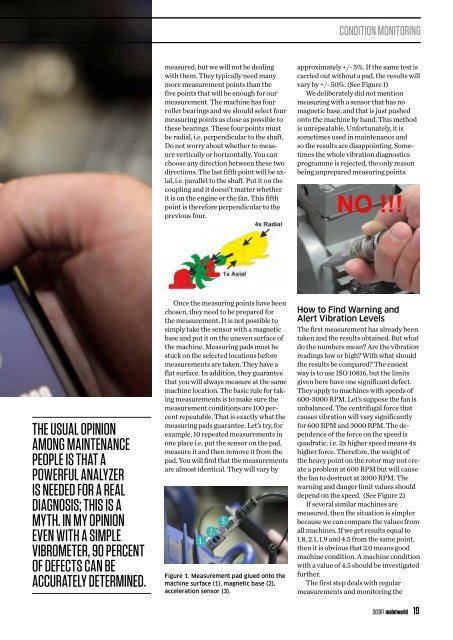
approximately +/- 5%. If the same test is<br />
carried out without a pad, the results will<br />
vary by +/- 50%. (See Figure 1)<br />
We deliberately did not mention<br />
measuring with a sensor that has no<br />
magnetic base, and that is just pushed<br />
onto the machine by hand. This method<br />
is unrepeatable. Unfortunately, it is<br />
sometimes used in maintenance and<br />
so the results are disappointing. Sometimes<br />
the whole vibration diagnostics<br />
programme is rejected, the only reason<br />
being unprepared measuring points.<br />
THE USUAL OPINION<br />
AMONG MAINTENANCE<br />
PEOPLE IS THAT A<br />
POWERFUL ANALYZER<br />
IS NEEDED FOR A REAL<br />
DIAGNOSIS; THIS IS A<br />
MYTH. IN MY OPINION<br />
EVEN WITH A SIMPLE<br />
VIBROMETER, 90 PERCENT<br />
OF DEFECTS CAN BE<br />
ACCURATELY DETERMINED.<br />
Once the measuring points have been<br />
chosen, they need to be prepared for<br />
the measurement. It is not possible to<br />
simply take the sensor with a magnetic<br />
base and put it on the uneven surface of<br />
the machine. Measuring pads must be<br />
stuck on the selected locations before<br />
measurements are taken. They have a<br />
flat surface. In addition, they guarantee<br />
that you will always measure at the same<br />
machine location. The basic rule for taking<br />
measurements is to make sure the<br />
measurement conditions are 100 percent<br />
repeatable. That is exactly what the<br />
measuring pads guarantee. Let’s try, for<br />
example, 10 repeated measurements in<br />
one place i.e. put the sensor on the pad,<br />
measure it and then remove it from the<br />
pad. You will find that the measurements<br />
are almost identical. They will vary by<br />
Figure 1. Measurement pad glued onto the<br />
machine surface (1), magnetic base (2),<br />
acceleration sensor (3).<br />
How to Find Warning and<br />
Alert Vibration Levels<br />
The first measurement has already been<br />
taken and the results obtained. But what<br />
do the numbers mean? Are the vibration<br />
readings low or high? With what should<br />
the results be compared? The easiest<br />
way is to use ISO 10816, but the limits<br />
given here have one significant defect.<br />
They apply to machines with speeds of<br />
600-3000 RPM. Let’s suppose the fan is<br />
unbalanced. The centrifugal force that<br />
causes vibration will vary significantly<br />
for 600 RPM and 3000 RPM. The dependence<br />
of the force on the speed is<br />
quadratic, i.e. 2x higher speed means 4x<br />
higher force. Therefore, the weight of<br />
the heavy point on the rotor may not create<br />
a problem at 600 RPM but will cause<br />
the fan to destruct at 3000 RPM. The<br />
warning and danger limit values should<br />
depend on the speed. (See Figure 2)<br />
If several similar machines are<br />
measured, then the situation is simpler<br />
because we can compare the values from<br />
all machines. If we get results equal to<br />
1.8, 2.1, 1.9 and 4.5 from the same point,<br />
then it is obvious that 2.0 means good<br />
machine condition. A machine condition<br />
with a value of 4.5 should be investigated<br />
further.<br />
The first step deals with regular<br />
measurements and monitoring the<br />
3/<strong>2017</strong> maintworld 19