


Create successful ePaper yourself
Turn your PDF publications into a flip-book with our unique Google optimized e-Paper software.
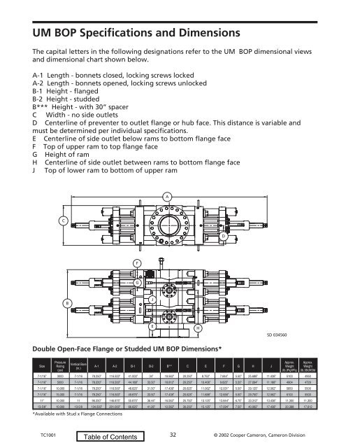
UM BOP Specifications and Dimensions<br />
The capital letters in the following designations refer to the UM BOP dimensional views<br />
and dimensional chart shown below.<br />
A-1 Length - bonnets closed, locking screws locked<br />
A-2 Length - bonnets opened, locking screws unlocked<br />
B-1 Height - flanged<br />
B-2 Height - studded<br />
B*** Height - with 30” spacer<br />
C Width - no side outlets<br />
D Centerline of preventer to outlet flange or hub face. This distance is variable and<br />
must be determined per individual specifications.<br />
E Centerline of side outlet below rams to bottom flange face<br />
F Top of upper ram to top flange face<br />
G Height of ram<br />
H Centerline of side outlet between rams to bottom flange face<br />
J Top of lower ram to bottom of upper ram<br />
A<br />
C<br />
D<br />
F<br />
G<br />
B<br />
J<br />
E<br />
H<br />
SD 034560<br />
Double Open-Face Flange or Studded UM BOP Dimensions*<br />
Size<br />
Pressure<br />
Rating<br />
(psi)<br />
Vertical Bore<br />
(in.)<br />
A-1 A-2 B-1 B-2 B*** C E F G H J<br />
Approx.<br />
Weight<br />
(lb.)FlgXFlg<br />
Approx.<br />
Weight<br />
(lb.)StdXStd<br />
7-1/16” 3000 7-1/16 78.250” 116.500” 41.000” 34” 18.562” 20.250” 8.750” 7.844” 5.50” 25.688” 11.438” 5100 4950<br />
7-1/16” 5000 7-1/16 78.250” 116.500” 44.188” 33.50” 18.812” 20.250” 10.406” 9.625” 5.50” 27.094” 11.188” 4904 4729<br />
7-1/16” 10,000 7-1/16 78.250” 116.500” 48.625” 31.50” 17.438” 20.625” 11.062” 12.031” 5.50” 29.125” 12.562” 5850 5500<br />
7-1/16” 15,000 7-1/16 78.250” 116.500” 49.875” 33.50” 17.438” 20.625” 11.688” 12.656” 5.50” 29.750” 12.562” 6100 5500<br />
11” 10,000 11 96.250” 146.875” 55.875” 36.44” 16.562” 25.750” 13.125” 13.844” 6.75” 33.312” 13.438” 11,300 11,300<br />
13-5/8” 10,000 13-5/8 134.500” 201.000” 66.625” 41.26” 12.562” 30.250” 15.125” 17.094” 7.50” 40.062” 17.438” 20,388 17,612<br />
*Available with Stud x Flange Connections<br />
TC1001 32 © <strong>2002</strong> Cooper Cameron, Cameron Division