CAT-NADNL22EN - Linear Guide Systems
Nadella Linear Guide Systems Catalog
Nadella Linear Guide Systems Catalog

You also want an ePaper? Increase the reach of your titles
YUMPU automatically turns print PDFs into web optimized ePapers that Google loves.
8.1<br />
FLEXI-LINE 645<br />
PRODUCT DESCRIPTION<br />
KEY BENEFITS<br />
• Dimensions according to DIN 645 with flexible configuration<br />
• For light and medium loads<br />
• Ready-to-install<br />
NX<br />
Aluminium guide rails FWN as well as carriages TA4 and TB4 are the components of this line. In addition to the standard dimensions that<br />
are DIN 645 compatible, the guide system can be adapted to customers’ requirements. Bore holes and threads on the guide rails can be<br />
made in any distance required, the carriages may have over-lengths and a special hole pattern.<br />
Compared to linear guides made of steel these guide rails and<br />
carriages weigh up to 45 % less and stand out due to their excellent<br />
running performance which minimises the driving power and<br />
reduces significantly the cost for motors and controls.<br />
With eccentric bolts the guide rollers of the carriages are kept free<br />
from play. However the user also has the possibility to change the<br />
settings, for example in case of vibrations, and to apply an individual<br />
preload on the guide system. On both sides of the carriages end<br />
plates with oil-soaked felt seals can be mounted to ensure lowwear<br />
operation.<br />
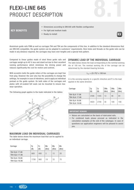
The following graph applies to the loads indicated in the tables:<br />
My<br />
Y<br />
Mx<br />
X<br />
DYNAMIC LOAD OF THE INDIVIDUAL CARRIAGE<br />
The table below shows the load corresponding to the nominal working<br />
life of 100 km. The nominal working life of the carriage can be<br />
determined by the standard bearing formula.<br />
L 10 = (Ci / Pi) 3 x 100 km<br />
Ci is the carrying capacity in a specific direction and Pi is the load<br />
applied in the same direction.<br />
Carriage<br />
TA4 GLA 17.06<br />
TB4 GLA 17.06<br />
TA4 GLA 19.06<br />
TB4 GLA 19.06<br />
Cy<br />
(N)<br />
Cz<br />
(N)<br />
CMx<br />
(Nm)<br />
CMy<br />
(Nm)<br />
CMz<br />
(Nm)<br />
2596 1445 13 46 84<br />
4920 2700 30 100 180<br />
Mz<br />
Z<br />
IMPORTANT REMARK<br />
• Values are calculated on the basis of lubricated rails.<br />
• For combined loads please proceed as indicated in the<br />
calculation examples at the end of the catalogue. In case of<br />
questions our application engineers will be pleased to assist<br />
you.<br />
MAXIMUM LOAD ON INDIVIDUAL CARRIAGES<br />
The table below shows the maximum load that can be applied to<br />
an individual carriage.<br />
Carriage<br />
TA4 GLA 17.06<br />
TB4 GLA 17.06<br />
TA4 GLA 19.06<br />
TB4 GLA 19.06<br />
Fy<br />
(N)<br />
Fz<br />
(N)<br />
Mx<br />
(Nm)<br />
My<br />
(Nm)<br />
Mz<br />
(Nm)<br />
600 400 5 15 20<br />
1700 960 19 33 70<br />
116 |