CAT-NADNL22EN - Linear Guide Systems
Nadella Linear Guide Systems Catalog
Nadella Linear Guide Systems Catalog

You also want an ePaper? Increase the reach of your titles
YUMPU automatically turns print PDFs into web optimized ePapers that Google loves.
TECHNICAL FEATURES<br />
NADELLA LINEAR SYSTEMS<br />
a)<br />
Y<br />
x F<br />
F F<br />
Y<br />
F 1 · ∆<br />
P z<br />
a =<br />
2 · I X<br />
F 1 ∆ z · tan <br />
P r = · + ∆<br />
( y)<br />
I X 2<br />
Iy<br />
P a =<br />
F · z F<br />
2 · I C<br />
F · (I x + 2 · x F ) F · z F · tan <br />
P r = +<br />
2 · I X 2 · I C<br />
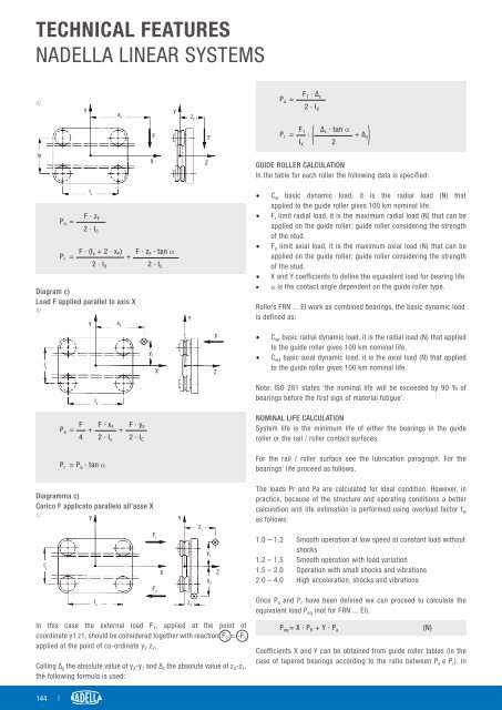
Diagram c)<br />
Load F applied parallel to axis X<br />
b)<br />
I y<br />
Y x F<br />
F F · x F F · y F<br />
P a = + +<br />
4 2 · I x 2 · I C<br />
P r = P a · tan <br />
I x<br />
z F<br />
Z<br />
X<br />
I x<br />
y F<br />
X Z<br />
Y<br />
F<br />
GUIDE ROLLER CALCULATION<br />
In the table for each roller the following data is specified:<br />
• C w basic dynamic load, it is the radial load (N) that<br />
applied to the guide roller gives 100 km nominal life.<br />
• F r limit radial load, it is the maximum radial load (N) that can be<br />
applied on the guide roller; guide roller considering the strength<br />
of the stud.<br />
• F a limit axial load, it is the maximum axial load (N) that can be<br />
applied on the guide roller; guide roller considering the strength<br />
of the stud.<br />
• X and Y coefficients to define the equivalent load for bearing life.<br />
• α is the contact angle dependent on the guide roller type.<br />
Rollers FRN ... EI work as combined bearings, the basic dynamic load<br />
is defined as:<br />
• C wr basic radial dynamic load, it is the radial load (N) that applied<br />
to the guide roller gives 100 km nominal life.<br />
• C wa basic axial dynamic load, it is the axial load (N) that applied<br />
to the guide roller gives 100 km nominal life.<br />
Note: ISO 281 states ‘the nominal life will be exceeded by 90 % of<br />
bearings before the first sign of material fatigue’.<br />
NOMINAL LIFE CALCULATION<br />
System life is the minimum life of either the bearings in the guide<br />
roller or the rail / roller contact surfaces.<br />
For the rail / roller surface see the lubrication paragraph. For the<br />
bearings’ life proceed as follows.<br />
Diagramma c)<br />
Carico F applicato parallelo all’asse X<br />
c)<br />
Y<br />
Y<br />
The loads Pr and Pa are calculated for ideal condition. However, in<br />
practice, because of the structure and operating conditions a better<br />
calculation and life estimation is performed using overload factor f w<br />
as follows:<br />
I y<br />
I x<br />
F 1<br />
X<br />
z 1<br />
y 1<br />
y 2<br />
Z<br />
1.0 – 1.2 Smooth operation at low speed at constant load without<br />
shocks<br />
1.2 – 1.5 Smooth operation with load variation<br />
1.5 – 2.0 Operation with small shocks and vibrations<br />
2.0 – 4.0 High acceleration, shocks and vibrations<br />
F 2<br />
z 2<br />
Once P a and P r have been defined we can proceed to calculate the<br />
equivalent load P eq (not for FRN ... EI).<br />
In this case the external load F₁, applied at the point of<br />
coordinate y1 z1, should be considered together with reaction F 2 = -F 1<br />
applied at the point of co-ordinate y 2 z 2 .<br />
Calling ∆ y the absolute value of y 2 -y 1 and ∆ z the absolute value of z 2 -z 1 ,<br />
the following formula is used:<br />
P eq = X · P R + Y · P a<br />
Coefficients X and Y can be obtained from guide roller tables (in the<br />
case of tapered bearings according to the ratio between P a e P r ). In<br />
(N)<br />
144 |