CAT-NADNL22EN - Linear Guide Systems
Nadella Linear Guide Systems Catalog
Nadella Linear Guide Systems Catalog

You also want an ePaper? Increase the reach of your titles
YUMPU automatically turns print PDFs into web optimized ePapers that Google loves.
ASSEMBLY INSTRUCTIONS<br />
GUIDE ROLLERS<br />
The eccentric guide rollers allow the preload or clearance of<br />
the carriage to be adjusted independently of the guide roller<br />
mounting hole positioning tolerance or the distance between the rails.<br />
Recommended mounting hole tolerance is H7. When adjusting the<br />
eccentric guide roller care has to be taken to avoid excessive preload.<br />
Excessive preload can reduce the life of the linear system. Set the<br />
preload turning the guide roller counterclockwise so that any movement<br />
caused by vibration will cause the nut to be tightened. Ensure<br />
the preload is not increased when tightening the nut.<br />
A simple way of setting a roller preload is as follows:<br />
• Move the slider on the guide, holding the roller being adjusted with<br />
two fingers to prevent it from rotating<br />
• Increase the preload by means of the wrench<br />
• Repeat step 1 making sure the roller slides without rolling<br />
• When it is no longer possible to prevent roller rolling, slightly<br />
decrease the preload and fully tighten the lock nut, thereby setting<br />
the position of the eccentric.<br />
GUIDES<br />
For single guide rail type FS, FWS, LS, DC, FWN and LM no<br />
special assembly instructions are necessary. For multiple parallel rails<br />
parallelism has to be checked to avoid guide rollers overload or<br />
excessive carriage play. When constant preload is required<br />
parallelism error has to be lower that 0.050 mm.<br />
Connection between the rail and the mounting surface has to<br />
be§designed accordingly with the operating condition to ensure<br />
proper product positioning and functionality. The direction and<br />
intensity of the load, the number and strength of the screws, the<br />
geometry of mounting surfaces, use of pins or wedges have to be<br />
evaluated to fully utilize the linear guide load capacity.<br />
life.<br />
10.1<br />
CALCULATING THE LOADS ON THE GUIDE ROLLERS<br />
In the case of complex load situations, with forces acting in different<br />
directions, calculating the reactions on the rollers is difficult and hard<br />
to simplify. In the event of the applied load having a direction<br />
parallel to one of the co-ordinate axes, the radial Pr and axial Pa<br />
components of the reactions on the most loaded roller can be obtained using<br />
elementary formulas. With reference to the diagrams shown, we<br />
obtain the load components on the rollers relevant for checking and<br />
calculating the life, applying the following methods.<br />
Angle α in the formulas is half the groove angle. Look in the<br />
dimensional table notes for the correct value.<br />
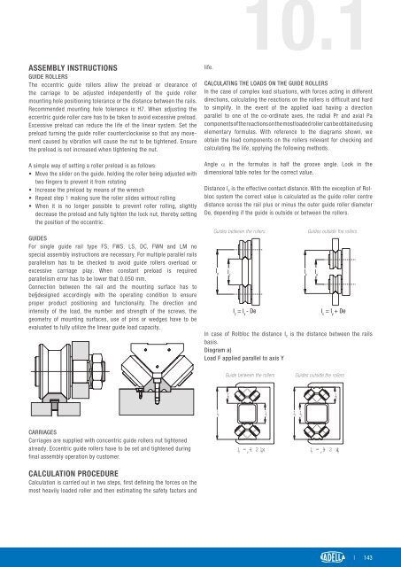
Distance I c is the effective contact distance. With the exception of Rolbloc<br />
system the correct value is calculated as the guide roller centre<br />
distance across the rail plus or minus the outer guide roller diameter<br />
De, depending if the guide is outside or between the rollers.<br />
<strong>Guide</strong>s Schiene between zwischen the den rollers Rollen<br />
l y<br />
l c<br />
l c<br />
= l y<br />
- De<br />
Rollen <strong>Guide</strong>s zwischen outside den the Schienen rollers<br />
l c<br />
= l y<br />
+ De<br />
In case of Rolbloc the distance I c is the distance between the rails<br />
basis.<br />
Diagram a)<br />
Load F applied parallel to axis Y<br />
l c<br />
l y<br />
<strong>Guide</strong>s between between the rollers the rollers<br />
<strong>Guide</strong>s outside outside the rollers the olle<br />
l y<br />
l h<br />
l h<br />
l c<br />
l c<br />
l y<br />
CARRIAGES<br />
Carriages are supplied with concentric guide rollers nut tightened<br />
already. Eccentric guide rollers have to be set and tightened during<br />
final assembly operation by customer.<br />
CALCULATION PROCEDURE<br />
Calculation is carried out in two steps, first defining the forces on the<br />
most heavily loaded roller and then estimating the safety factors and<br />
l c<br />
= y<br />
- l 2 l h<br />
x<br />
l c<br />
= y<br />
l+ 2 x l h<br />
| 143