CAT-NADNL22EN - Linear Guide Systems
Nadella Linear Guide Systems Catalog
Nadella Linear Guide Systems Catalog

You also want an ePaper? Increase the reach of your titles
YUMPU automatically turns print PDFs into web optimized ePapers that Google loves.
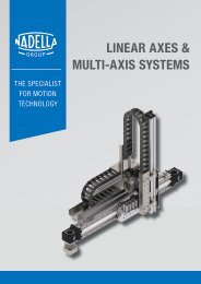
TECHNICAL FEATURES<br />
NADELLA LINEAR SYSTEMS<br />
Nominal life<br />
X = 1<br />
Y = 3.38<br />
Equivalent dynamic load<br />
P eq = 1 · 3881 + 3.7 · 1050 = 7766 N<br />
41000 10/3<br />
L 10 = 100 ·<br />
(<br />
7766 · 1<br />
)<br />
Limit load check<br />
Equivalent limit load F k<br />
K = P a / P r = 0.27<br />
= 25622,5 km<br />
Load on rollers<br />
The effective center axis l c is 400 – 85 – 85 = 230 mm<br />
P a =<br />
6000 · 160<br />
2 · 230<br />
= 2087 N<br />
6000 · (350 + 0) 6000 · 160 · tan 45<br />
P r = + = 5087 N<br />
2 · 350 2 · 230<br />
Nominal life<br />
From the Rolbloc table<br />
X = 1<br />
Y = 1<br />
F k =<br />
11900 · 4250<br />
0.27 · 11900 + (1 – 0.27 · tan 40) · 4800<br />
<strong>Guide</strong> roller safety coefficient<br />
F k / P r = 8248 / 3881 = 2,1<br />
= 8248 N<br />
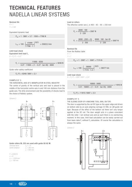
EXAMPLE N° 2:<br />
THE HORIZONTAL AXIS OF A MANIPULATOR IN STEEL INDUSTRY<br />
The centre of gravity of the vertical axis and load is placed in the<br />
middle of the horizontal centre-axis lx and 160 mm distance from the<br />
guide axis. The dirty environment and the possibility of shocks lead to<br />
the choice of Rolbloc system.<br />
P eq = 1 · 2087 + 1 · 5087 = 7174 N<br />
59000 10/3<br />
L 10 = 100 · = 36577 km<br />
(<br />
7174 · 1.4<br />
)<br />
Limit load check<br />
K = P a / P r = 2087 / 5087 = 0.41<br />
F k =<br />
16800 · 8400<br />
0.41 · 16800 + (1 – 0.41 · tan 45) · 8400<br />
F k / P r = 11915 / 5087 = 2.3<br />
= 11915 N<br />
Scheme 2:<br />
lx<br />
Y<br />
X<br />
ly<br />
lc<br />
Y<br />
Z<br />
EXAMPLE N° 3:<br />
THE SLIDING DOOR OF A MACHINE TOOL (RAIL ON TOP)<br />
The door is supported by the rail DC type on the upper edge and driven<br />
on bottom side by an auto-aligning carriage C3 RAL on LM guide rail<br />
type. Because of the effect of the bottom rail there isn’t any torque<br />
applied at the DC rail. The door weight acts in a plane coincident<br />
with the roller / rail vertical axis and as such there is no overturning<br />
moment. In this case, limit load calculation can be easily carried out<br />
from basic data F r without F k calculation. Of course the calculation is<br />
always the same.<br />
Scheme 3:<br />
F<br />
F<br />
Y<br />
Y<br />
<strong>Guide</strong> rollers BL 252 are used with guide GU 62 M:<br />
Overload factor f w = 1.4<br />
Centre distance I x = 350 mm<br />
I y = 400 mm<br />
Z F<br />
Z<br />
ly<br />
F<br />
l x<br />
X<br />
F = 6000 N<br />
x = 0<br />
y = –1000 mm<br />
z F = 160 mm<br />
X F<br />
146 |