CAT-NADNL22EN - Linear Guide Systems
Nadella Linear Guide Systems Catalog
Nadella Linear Guide Systems Catalog

You also want an ePaper? Increase the reach of your titles
YUMPU automatically turns print PDFs into web optimized ePapers that Google loves.
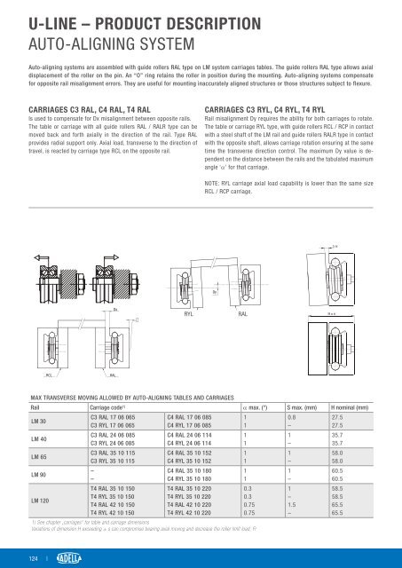
U-LINE – PRODUCT DESCRIPTION<br />
AUTO-ALIGNING SYSTEM<br />
Auto-aligning systems are assembled with guide rollers RAL type on LM system carriages tables. The guide rollers RAL type allows axial<br />
displacement of the roller on the pin. An “O” ring retains the roller in position during the mounting. Auto-aligning systems compensate<br />
for opposite rail misalignment errors. They are useful for mounting inaccurately aligned structures or those structures subject to flexure.<br />
CARRIAGES C3 RAL, C4 RAL, T4 RAL<br />
Is used to compensate for Dx misalignment between opposite rails.<br />
The table or carriage with all guide rollers RAL / RALR type can be<br />
moved back and forth axially in the direction of the rail. Type RAL<br />
provides radial support only. Axial load, transverse to the direction of<br />
travel, is reacted by carriage type RCL on the opposite rail.<br />
CARRIAGES C3 RYL, C4 RYL, T4 RYL<br />
Rail misalignment Dy requires the ability for both carriages to rotate.<br />
The table or carriage RYL type, with guide rollers RCL / RCP in contact<br />
with a steel shaft of the LM rail and guide rollers RALR type in contact<br />
with the opposite shaft, allows carriage rotation ensuring at the same<br />
time the transverse direction control. The maximum Dy value is dependent<br />
on the distance between the rails and the tabulated maximum<br />
angle ‘α’ for that carriage.<br />
NOTE: RYL carriage axial load capability is lower than the same size<br />
RCL / RCP carriage.<br />
RYL<br />
RAL<br />
MAX TRANSVERSE MOVING ALLOWED BY AUTO-ALIGNING TABLES AND CARRIAGES<br />
Rail Carriage code 1) α max. (°) S max. (mm) H nominal (mm)<br />
LM 30<br />
LM 40<br />
LM 65<br />
LM 90<br />
LM 120<br />
C3 RAL 17 06 065<br />
C3 RYL 17 06 065<br />
C3 RAL 24 06 085<br />
C3 RYL 24 06 085<br />
C3 RAL 35 10 115<br />
C3 RYL 35 10 115<br />
–<br />
–<br />
T4 RAL 35 10 150<br />
T4 RYL 35 10 150<br />
T4 RAL 42 10 150<br />
T4 RYL 42 10 150<br />
C4 RAL 17 06 085<br />
C4 RYL 17 06 085<br />
C4 RAL 24 06 114<br />
C4 RYL 24 06 114<br />
C4 RAL 35 10 152<br />
C4 RYL 35 10 152<br />
C4 RAL 35 10 180<br />
C4 RYL 35 10 180<br />
T4 RAL 35 10 220<br />
T4 RYL 35 10 220<br />
T4 RAL 42 10 220<br />
T4 RYL 42 10 220<br />
1<br />
1<br />
1<br />
1<br />
1<br />
1<br />
1<br />
1<br />
0.3<br />
0.3<br />
0.75<br />
0.75<br />
1) See chapter „carriages“ for table and carriage dimensions<br />
Variations of dimension H exceeding ± s can compromise bearing axial moving and decrease the roller limit load, Fr<br />
0.8<br />
–<br />
1<br />
–<br />
1<br />
–<br />
1<br />
–<br />
1<br />
–<br />
1.5<br />
–<br />
27.5<br />
27.5<br />
35.7<br />
35.7<br />
58.0<br />
58.0<br />
60.5<br />
60.5<br />
58.5<br />
58.5<br />
65.5<br />
65.5<br />
124 |