CAT-NADNL22EN - Linear Guide Systems
Nadella Linear Guide Systems Catalog
Nadella Linear Guide Systems Catalog

Create successful ePaper yourself
Turn your PDF publications into a flip-book with our unique Google optimized e-Paper software.
U-LINE – PRODUCT DESCRIPTION<br />
LM SYSTEM<br />
KEY BENEFITS<br />
• For light and medium loads<br />
• Compact design of U-Line guides with inside carriage<br />
• <strong>Guide</strong> rails with stainless steel shafts<br />
• Carriages with stainless guide rollers<br />
NX<br />
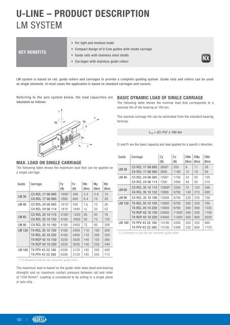
LM system is based on rail, guide rollers and carriages to provide a complete guiding system. <strong>Guide</strong> rails and rollers can be used<br />
as single elements. In most cases the application is based on standard carriages and cursors.<br />
Referring to the axis system below, the load capacities are<br />
tabulated as follows:<br />
BASIC DYNAMIC LOAD OF SINGLE CARRIAGE<br />
The following table shows the nominal load that corresponds to a<br />
nominal life of the bearing at 100 km.<br />
The nominal carriage life can be estimated from the standard bearing<br />
formula.<br />
L 10 = (Ci / Pi) 3 x 100 km<br />
Ci and Pi are the basic capacity and load applied for a specifi c direction.<br />
MAX. LOAD ON SINGLE CARRIAGE<br />
The following table shows the maximum load that can be applied on<br />
a single carriage.<br />
<strong>Guide</strong> Carriage Fy<br />
(N)<br />
LM 30<br />
C3 RCL 17 06 065<br />
C4 RCL 17 06 085<br />
LM 40 C3 RCL 24 06 085<br />
C4 RCL 24 06 114<br />
LM 65<br />
C3 RCL 35 10 115<br />
C4 RCL 35 10 152<br />
1000 1)<br />
1000<br />
1810 1)<br />
1810<br />
4160 1)<br />
4160<br />
Fz<br />
(N)<br />
300<br />
600<br />
520<br />
1040<br />
1200<br />
2400<br />
Mx<br />
(Nm)<br />
3.3<br />
6.4<br />
7.6<br />
15<br />
26<br />
50<br />
My<br />
(Nm)<br />
5.8<br />
10<br />
15<br />
25<br />
45<br />
75<br />
Mz<br />
(Nm)<br />
10<br />
20<br />
26<br />
52<br />
78<br />
155<br />
LM 90 C4 RCL 35 10 180 4160 2400 75 95 200<br />
LM 120 T4 RCL 35 10 150<br />
T4 RCL 35 10 220<br />
T4 RCP 42 10 150<br />
T4 RCP 42 10 220<br />
LM 180 T4 PFV 43 22 180<br />
T4 PFV 43 22 280<br />
4160<br />
4160<br />
5250<br />
5250<br />
6300<br />
6300<br />
2400<br />
2400<br />
3030<br />
3030<br />
3120<br />
3120<br />
1) Fy directed to load the two concentric guide rollers<br />
110<br />
110<br />
140<br />
140<br />
185<br />
185<br />
120<br />
200<br />
150<br />
250<br />
200<br />
350<br />
200<br />
350<br />
260<br />
440<br />
400<br />
715<br />
<strong>Guide</strong> Carriage Cy<br />
(N)<br />
LM 30<br />
C3 RCL 17 06 065<br />
C4 RCL 17 06 085<br />
LM 40 C3 RCL 24 06 085<br />
C4 RCL 24 06 114<br />
LM 65<br />
C3 RCL 35 10 115<br />
C4 RCL 35 10 152<br />
2800 2)<br />
2800<br />
7200 2)<br />
7200<br />
15800 2)<br />
15800<br />
Cz<br />
(N)<br />
550<br />
1100<br />
1700<br />
3400<br />
3350<br />
6700<br />
CMx<br />
(Nm)<br />
6<br />
12<br />
24<br />
48<br />
70<br />
140<br />
CMy<br />
(Nm)<br />
11<br />
19<br />
50<br />
83<br />
125<br />
210<br />
CMz<br />
(Nm)<br />
28<br />
56<br />
105<br />
210<br />
300<br />
600<br />
LM 90 C4 RCL 35 10 180 15800 6700 220 250 700<br />
LM 120 T4 RCL 35 10 150<br />
T4 RCL 35 10 220<br />
T4 RCP 42 10 150<br />
T4 RCP 42 10 220<br />
LM 180 T4 PFV 43 22 180<br />
T4 PFV 43 22 280<br />
15800<br />
15800<br />
24000<br />
24000<br />
15190<br />
15190<br />
6700<br />
6700<br />
11000<br />
11000<br />
5300<br />
5300<br />
2) Cy directed to load the two concentric guide rollers<br />
300<br />
300<br />
500<br />
500<br />
320<br />
320<br />
330<br />
560<br />
530<br />
900<br />
335<br />
600<br />
780<br />
1335<br />
1190<br />
2030<br />
965<br />
1725<br />
The maximum load is based on the guide roller data (stud and bearing<br />
strength) and on maximum contact pressure between rail and roller<br />
of 1250 N/mm². Loading is considered to be acting in a single plane<br />
or axis only.<br />
122 |