

TECHNOLOGY DIGEST - Draper Laboratory
TECHNOLOGY DIGEST - Draper Laboratory
TECHNOLOGY DIGEST - Draper Laboratory

Create successful ePaper yourself
Turn your PDF publications into a flip-book with our unique Google optimized e-Paper software.
Navigation Implementation Details<br />
Navigation uses data from a dual-antenna GPS navigation<br />
package to compute position and flight path azimuth for<br />
use by guidance, and flight path azimuth and flight path<br />
azimuth rate (turning rate) for use by control. Using GPSmeasured<br />
velocity with respect to the ground together<br />
with a simple analytic model of system air speed and GPSmeasured<br />
heading, navigation estimates wind velocity. The<br />
wind velocity estimate is used to correct an a priori table<br />
of wind vs. altitude; the correction is largest for altitudes<br />
close to the altitude at which navigation’s wind estimate is<br />
valid. Navigation sends the corrected wind table to guidance.<br />
Early in the flight, navigation monitors the sink rate<br />
in order to detect canopy inflation; this information is<br />
important for system moding. Navigation interfaces are<br />
shown in Figure 3.<br />
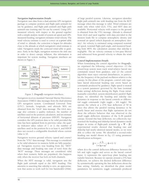
Figure 3. Dragonfly navigation interfaces.<br />
Navigation receives standard National Marine Electronics<br />
Association (NMEA) data messages from the dual-antenna<br />
GPS navigation system. Coordinated Universal Time<br />
(UTC), latitude, longitude, and altitude MSL are<br />
obtained from the “GGA” data message. The GGA message<br />
also contains a quality indicator, the number of<br />
satellites used in the position calculation, and an estimate<br />
of horizontal dilution of precision (HDOP). Navigation<br />
considers the GPS position data to be valid provided the<br />
time has been updated from its previous value, the quality<br />
indicator takes values of 1 or 2, the number of<br />
satellites used in the position fix is at least 4, and HDOP<br />
does not exceed a configurable threshold whose current<br />
value is 10.<br />
Navigation receives ground velocity (speed and course)<br />
from the “VTG” data message. This message is considered<br />
to be valid whenever its numeric fields are fully populated.<br />
Navigation receives true heading from the “HDT”<br />
data message and heading rate (rate of turn) from the<br />
“ROT” message. These messages are considered valid<br />
when their numeric fields are populated; this happens<br />
only when the receiver has lock on both channels.<br />
When the HDT message is valid, navigation sets the<br />
flight path azimuth equal to the HDT heading. This<br />
amounts to asserting that sideslip is zero, an approximation<br />
that seems to work well for low bandwidth GN&C<br />
18<br />
Mode<br />
Control<br />
GPS<br />
Interface<br />
Mission<br />
Loads<br />
Mode<br />
h, x, y, χ<br />
t, h, lat, lon, v,<br />
Wind<br />
course<br />
Table<br />
ψ, dψ/dt, χ, dχ/dt,<br />
Validity Data<br />
Impact Point<br />
Navigation<br />
Submode<br />
Release Point<br />
a priori<br />
Wind Table<br />
Autonomous Guidance, Navigation, and Control of Large Parafoils<br />
Submode<br />
Sink Rate<br />
Stabilized<br />
Guidance<br />
Control<br />
Mode<br />
Control<br />
of large parafoil systems. Likewise, navigation identifies<br />
flight path azimuth rate with heading rate from the ROT<br />
message when this message is valid. Wind estimates are<br />
made only when valid GGA, VTG, and HDT data are<br />
available. Horizontal velocity with respect to the ground<br />
is obtained from the VTG message. Altitude is obtained<br />
from GGA and used together with data provided in the<br />
mission loads file to compute atmospheric density and<br />
nominal air speed (which depends on atmospheric density).<br />
Air velocity is estimated using computed nominal<br />
air speed, nominal flight path angle, and measured heading<br />
from HDT; the calculation assumes that sideslip is<br />
negligible. The air velocity estimate is low-pass filtered<br />
and subtracted from ground velocity to obtain the wind<br />
estimate.<br />
Control Implementation Details<br />
When formulating the control algorithm for Dragonfly,<br />
we stipulated the following control objectives: (1) the<br />
closed-loop system must track wind-relative lateral rate<br />
commands issued from guidance, and (2) the control<br />
algorithm must reject external disturbances, in particular,<br />
the frequency of the payload oscillation relative to the<br />
canopy. In this phase of the program, control only regulates<br />
lateral directional heading rate errors based on<br />
commands produced by guidance; flight speed is treated<br />
as a system parameter governed by the base (nominal<br />
brake setting) deflection during the flight. From initial,<br />
manually-controlled, system-identification parafoil flight<br />
drops, we identified the heading and sideslip rate<br />
dynamics in response to the lateral controls or differential<br />
toggle commands (right toggle – left toggle). We<br />
operate the vehicle at a 25% base deflection of 50 in<br />
since this allows the parafoil turning dynamics to be<br />
nearly linear and ensures that flight operations do not<br />
show the reflexive behavior that was observed in the<br />
small toggle deflection dynamics of the X-38 parafoil<br />
canopy. Around this base deflection, we collectively represented<br />
the heading and slideslip lateral dynamics mode<br />
shapes in terms of flight-path azimuth (χ = Ψ – β);<br />
experimental results showed that heading rate and<br />
slideslip had nearly identical natural modes, so we were<br />
able to collect the terms. We identified a second-order<br />
heading rate model shown in Eq. (1) using parameter<br />
identification techniques:<br />
(1)<br />
where ∆ is the control deflection difference between the<br />
left and right toggles and serves as the lateral control<br />
input. G represents the open-loop plant heading rate<br />
transfer function. Because we operate around a 25% base<br />
deflection, we achieve the desired deflection difference<br />
by symmetrically operating the line deflections about the<br />
base setting. Similarly, we identified the plant model<br />
parameters for symmetric toggle commands produced


