

TECHNOLOGY DIGEST - Draper Laboratory
TECHNOLOGY DIGEST - Draper Laboratory
TECHNOLOGY DIGEST - Draper Laboratory

You also want an ePaper? Increase the reach of your titles
YUMPU automatically turns print PDFs into web optimized ePapers that Google loves.
(2)<br />
This equation is nonlinear in z, but for small motions ∆z<br />
around the equilibrium displacement, d, a linear equation<br />
for the total restoring force in the z-direction can be used<br />
FT = -N . k . ∆z (3)<br />
Here N is the total tether count and k is the linearized<br />
spring constant of a single tether<br />
(4)<br />
E is elastic modulus, A is tether cross-sectional area, L is<br />
tether length, and θ0 is the as-built tether angle (Figure 7).<br />
This spring constant greatly exceeds that of the bending<br />
stiffness for even modest angles. The resonant frequency is<br />
now given by the familiar relation<br />
It should be noted that x- and y-axis resonance frequencies<br />
can be calculated simply by replacing cos (θ0) with sin<br />
(θ0) in the equation for the spring constant. It follows from<br />
this that resonant frequencies and maximum g loads are<br />
higher in the x and y directions.<br />
Test units with a range of built-in tether angles were built<br />
and tested to validate the model. A small magnetically permeable<br />
disk was attached to the cell in these test units and<br />
excited by a miniature electromagnet. Displacement was<br />
measured with an interferometer as the excitation frequency<br />
was swept manually. Fundamental mode resonances<br />
were calculated by fitting the data to a standard massspring-damper<br />
model. Measured resonant frequency data<br />
were estimated to be accurate to better than 1%. The<br />
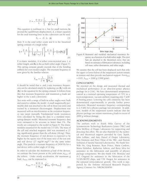
results are compared to the model in Figure 8. The elastic<br />
modulus assumed for the model was 3.5 GPa. The mass of<br />
the cell and attached magnetic disk was estimated at 27<br />
mg, significantly greater than the cell alone (18 mg). Thus,<br />
the resonant frequency of real devices is expected to be<br />
higher by the square root of the mass ratio of the test unit<br />
and real device (27 mg/18 mg) 0.5 for the same tether<br />
angle. This predicts a resonant frequency of 2450 Hz for a<br />
real device with a tether angle of 10 deg.<br />
In order to calculate the maximum g load of the devices,<br />
we estimate the forces present at the yield strain, εmax, of<br />
the tethers. Under steady acceleration, the maximum g<br />
load, Amax, can be expressed as<br />
30<br />
An Ultra-Low-Power Physics Package for a Chip-Scale Atomic Clock<br />
(5)<br />
(6)<br />
Resonant Frequency (Hz)<br />
3000<br />
2500<br />
2000<br />
1500<br />
1000<br />
500<br />
Model<br />
Measured<br />
0<br />
0 5 10 15<br />
Tether Angle (deg)<br />
Figure 8. Measured and modeled mechanical resonance frequency<br />
as a function of as-built tether angle. The error<br />
bars are attached to the theoretical curve; they are<br />
based on estimates of fabrication tolerances, including<br />
cell mass, tether dimensions, and tether angle.<br />
We assume that the cell has been displaced such that only<br />
the upper or lower halves of the suspension system remain<br />
in tension and thus provide mechanical support. For εmax<br />
= 0.03, Amax = 2200 g (1500 grms).<br />
CONCLUSIONS<br />
We reported on the design and measured thermal and<br />
mechanical performance of an ultra-low-power physics<br />
package for a CSAC. We have demonstrated temperature<br />
control at a nominal operating temperature of 75°C in a<br />
room-temperature, vacuum ambient requiring only 7 mW<br />
of heating power. Lowering the cell’s emissivity has been<br />
demonstrated experimentally to provide further power<br />
reduction. Measured resonance frequency corresponding<br />
to 2.5 kHz for a physics package was presented. In addition,<br />
models of the suspension system indicate that the<br />
physics package can sustain maximum g loads in excess of<br />
2000 g without damage.<br />
ACKNOWLEDGMENTS<br />
The authors wish to thank Mike Garvey of the<br />
Symmetricom Technology Realization Center (TRC) and<br />
John McElroy of <strong>Draper</strong> <strong>Laboratory</strong> for supporting and<br />
directing this effort. We are also thankful for the technical<br />
and theoretical support provided by Gary Tepolt,<br />
John LeBlanc, and Amy Duwel of <strong>Draper</strong> <strong>Laboratory</strong>,<br />
Don Emmons and Peter Vlitas of the TRC, and Darwin<br />
Serkland of Sandia National Laboratories. We thank Yen-<br />
Wah Ho, Greg Romano, Ryan Prince, Maria Cardoso,<br />
Maria Holmboe, Katherine Ashton, and Bessy Silva for<br />
assistance in the fabrication and assembly of physics<br />
package components. We also thank V.M. Montano and<br />
A.T. Ongstad for assistance in the fabrication of the<br />
VCSEL/RCPD chips, and T.W. Hargett for assistance in<br />
the epitaxial semiconductor growth. This work is supported<br />
by the Defense Advanced Research Projects<br />
Agency, Contract No. NBCHC020050.


