

TECHNOLOGY DIGEST - Draper Laboratory
TECHNOLOGY DIGEST - Draper Laboratory
TECHNOLOGY DIGEST - Draper Laboratory

You also want an ePaper? Increase the reach of your titles
YUMPU automatically turns print PDFs into web optimized ePapers that Google loves.
Sea-Level Airspeed (ft/s)<br />
0<br />
0 20 40 60 80 100 120<br />
Brake Command (in)<br />
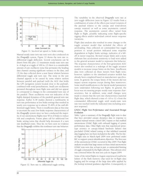
Figure 11. Sea-level air speed vs. brake setting.<br />
Manual steady-state turn rate tests were also conducted on<br />
the Dragonfly system. Figure 12 shows the turn rate vs.<br />
differential toggle deflection. Several conclusions can be<br />
drawn from this plot: (1) maximum steady-state turn rate<br />
is ~9 deg/s at a toggle of 100 in, (2) there is a considerable<br />
amount of yaw oscillatory noise that permeates the heading<br />
data channel causing significant variance in the data, and<br />
(3) the data collected show a near linear relation between<br />
differential toggle and turn rate. The noise in the yaw<br />
channel appears to be caused by some relative motion<br />
between parafoil and payload (with the AGU that holds<br />
the GPS navigation system located close to the payload),<br />
combined with wind perturbations. Small yaw oscillations<br />
persisted throughout most flight tests and did not appear<br />
to correspond to changes in the commanded turn rate of<br />
the parafoil. These oscillations were not indicative of the<br />
highly damped dynamics of the parafoil’s general turn rate<br />
response. Earlier X-38 studies showed a nonlinearity in<br />
turn rate performance at low brake settings that resulted in<br />
nearly zero response up to almost 35-40% of the stall differential<br />
toggle limits. There is insufficient data at this time<br />
to ascertain the exact low-brake response characteristics of<br />
the Dragonfly system since we have conducted the majority<br />
of our autonomous flights near 50 in of brake to reduce<br />
risk and complexity. Future plans call for additional low<br />
brake setting turns that should help document if a turn<br />
rate deadband exists. Thus far, we have seen no evidence<br />
that the Dragonfly exhibits this nonlinear turn-rate behavior.<br />
Turn Rate (deg/s)<br />
22<br />
70<br />
60<br />
50<br />
40<br />
30<br />
20<br />
10<br />
15.0<br />
10.0<br />
5.0<br />
0.0<br />
-5.0<br />
-10.0<br />
Flight Data<br />
Model<br />
-15.0 -125 -100 -75 -50 -25 0 25 50 75 100 125<br />
Differential Toggle (in)<br />
Figure 12. Turn rate vs. differential toggle setting.<br />
Autonomous Guidance, Navigation, and Control of Large Parafoils<br />
The variability in the observed Dragonfly turn rate at<br />
zero toggle deflection (seen in Figure 12) results from a<br />
combination of some of the effects just noted (rotation of<br />
the payload relative to the canopy and wind-driven<br />
canopy rotation) as well as some asymmetric control<br />
response. The asymmetric control effect varied from<br />
flight to flight, possibly indicating some flight-specific<br />
rigging effects and/or individual control motor response<br />
variations.<br />
Flight data analysis also resulted in some changes to the<br />
toggle actuator model that included the effects of<br />
aeroloading. Data collected on commanded line toggle<br />
position vs. actual position indicated some response<br />
degradation at higher brake settings, indicative of a falloff<br />
in motor response. Revised torque limits and a more<br />
elaborate line acceleration sensitivity to load were added<br />
to the general actuator model to represent this behavior.<br />
The response characteristics of the first-generation AGU<br />
motor also resulted in a redesign of the toggle actuator<br />
models to increase torque limits on the lines. Insufficient<br />
data were collected on these motors from flight tests;<br />
however, updates to the simulated actuator models has<br />
already been completed based on manufacturer specifications.<br />
In general, the torque limits of the motors did not<br />
impact system response except during flare maneuvers.<br />
Some small modifications to the lateral model parameters<br />
were undertaken following test flights. In general, the<br />
focus was on ensuring proper steady-state response characteristics,<br />
but in addition, some small changes were<br />
made to ensure that the turn rate characteristics matched<br />
flight data, which showed a time of ~10 to 12 s from the<br />
commanded differential toggle until steady-state turn<br />
rate was reached (with the indicated time including actuator<br />
response).<br />
GN&C Flight Test Performance and Associated Design<br />
Evolution<br />
Table 1 gives a summary of the Dragonfly flight tests to date<br />
that have provided canopy dynamics data in response to<br />
scripted manual remote control (R/C) inputs or that enabled<br />
autonomous GN&C flight with onboard logging of system<br />
performance data. Other flight tests that experienced prototype<br />
avionics or canopy-related hardware failures that<br />
precluded GN&C-related testing or that inhibited essential<br />
data logging have not been included in the table. The five listed<br />
flight tests in March-April 2004 were performed under<br />
R/C to support system identification objectives. The first tests<br />
of the autonomous GN&C occurred in May 2004. Post-flight<br />
analysis revealed that large misses in these initial autonomous<br />
GN&C tests were due, at least in part, to unintended limiting<br />
of toggle commands by the flight software. This software error<br />
was corrected before the next test cycle in August 2004.<br />
Some of the initial flights in August experienced read/write<br />
failure of the flash memory chip used for in-flight data<br />
logging and for storage of the large data table applied by<br />
the lookup terminal guidance algorithm. Consequently, to


