

TECHNOLOGY DIGEST - Draper Laboratory
TECHNOLOGY DIGEST - Draper Laboratory
TECHNOLOGY DIGEST - Draper Laboratory

You also want an ePaper? Increase the reach of your titles
YUMPU automatically turns print PDFs into web optimized ePapers that Google loves.
Assembly and Packaging<br />
The cell and suspension structures are assembled with epoxy.<br />
EPO-TEK ® 353ND is used for its optical transmission characteristics<br />
and its low outgassing properties. An exploded<br />
view before assembly is depicted in Figure 1. Individual cells<br />
are mounted in the suspension structure. The thermal control<br />
suspension structure is placed face-down in an<br />
alignment fixture. The cell is mounted mirror-side down on<br />
the central attachment plate of the suspension via manual<br />
dispensing of epoxy. After curing, the adhesive interface<br />
thickness is 5 µm. The aluminum frame spacer is then<br />
aligned via fiducial marks and adhered to the silicon frame<br />
similarly. Finally, the VCSEL/PD suspension is aligned using<br />
another fiducial mark on the frame. Epoxy attaches the center<br />
plate to the cell and the frame to the frame spacer.<br />
The VCSEL/PD die is attached to the cell via solder reflow.<br />
First, 0.018-in solder balls are attached to the VCSEL/PD<br />
pads. The VCSEL/PD solder balls are aligned to pad locations<br />
on the center plate of the VCSEL/PD suspension and<br />
attached by reflowing the solder. Simultaneously, solder balls<br />
are attached to pads on the frame of the VCSEL/PD suspension<br />
to enable mounting of the frame assembly to a ceramic<br />
LCC. The LCC is then aligned and a final reflow is done to<br />
connect the frame pads to those of the LCC. The heater and<br />
temperature sensor are connected via wire bond to corner<br />
pads in the LCC. Finally, an alumina lid containing an activated<br />
getter is attached in vacuum. A solder preform is<br />
mounted onto the seal-ring of the LCC and reflowed to seal<br />
the device. Including the vacuum package, the overall size<br />
of the physics package is approximately 0.6 cm3 .<br />
Performance Characteristics<br />
Thermal Control<br />
The cell temperature is maintained through integrated single-element<br />
resistive platinum temperature-sensing and<br />
heating elements, both of which are patterned directly onto<br />
the central polyimide plate of the thermal control side of the<br />
suspension structure. Measured temperature coefficients of<br />
resistance for the sputtered films are 2300 ppm/°C with a<br />
4% variation across a 4-in wafer. The temperature sensor is<br />
distributed uniformly across the cell face to provide an accurate<br />
average temperature measurement of the vapor cell.<br />
The portion of the trace that runs along the suspension tether<br />
from the center plate to outer frame bond pad is designed<br />
to have relatively low resistance (0.9% in current devices) to<br />
prevent partial sensing of the frame (i.e, ambient) temperature.<br />
The sense resistor is sized (10 kΩ) to achieve<br />
approximately 0.1°C temperature sensitivity with lowpower<br />
readout electronics. The heater resistance is<br />
distributed around the periphery of the cell rather than uniformly<br />
across the plate surface. This provides a more<br />
uniform temperature because most of the heat transfer away<br />
from this surface is through the silicon walls of the cell to all<br />
cell faces, which then radiate heat to the LCC package. The<br />
heater resistance is sized (400 Ω) such that power is<br />
delivered efficiently from the control electronics (3-V supply)<br />
while still maintaining sufficient voltage overhead to<br />
28<br />
An Ultra-Low-Power Physics Package for a Chip-Scale Atomic Clock<br />
provide fast device turn-on and good control response. In<br />
the case of the heater, the tether traces contribute to inefficiency<br />
by heating the tethers and the frame (7.5% in current<br />
devices). Both the heating and sensing resistors are configured<br />
such that current flowing through one segment of the<br />
resistor is balanced by a current in another segment in close<br />
proximity that is flowing in the opposite direction, which<br />
minimizes magnetic fields in the vicinity of the vapor cell.<br />
Heat loss to the frame and package occurs through radiation,<br />
gas conduction and convection, and conduction in<br />
the suspension tethers. Gaseous conduction and convection<br />
are eliminated by vacuum packaging the device.<br />
However, even at atmospheric pressure, convection is suppressed<br />
due to the small size of the gap between the heated<br />
device and the LCC package. Radiation is driven by surface<br />
area and emissivity. Gas conduction is driven by gap<br />
dimensions, gas composition, and pressure. The bulk conduction<br />
is determined by thermal conductivity and the<br />
shape and size of the suspension tethers and their metal<br />
interconnect. Detailed radiation models must account for<br />
the multiple surface emissivities and shape factors of the<br />
system. However, the heated cesium cell will have radiative<br />
heat loss with a temperature dependence given by<br />
P = ε . σ . Acell . (Tcell 4 – Tamb 4 ) (1)<br />
where ε is a parameter that embodies the relative emissivities<br />
of the cell and heat-reflecting package, Acell is the surface<br />
area of the cell, and σ is the Stefan-Boltzmann constant. As<br />
a general rule, heat loss by thermal radiation is reduced by<br />
minimizing the cell’s surface area and average emissivity. The<br />
cell has four saw-diced silicon surfaces, one polyimide-andplatinum-covered<br />
surface, and one surface of gallium<br />
arsenide (the VCSEL/PD). These materials all have emissivities<br />
around 0.5, with variation depending on surface finish.<br />
Some materials, such as polished aluminum, can have emissivities<br />
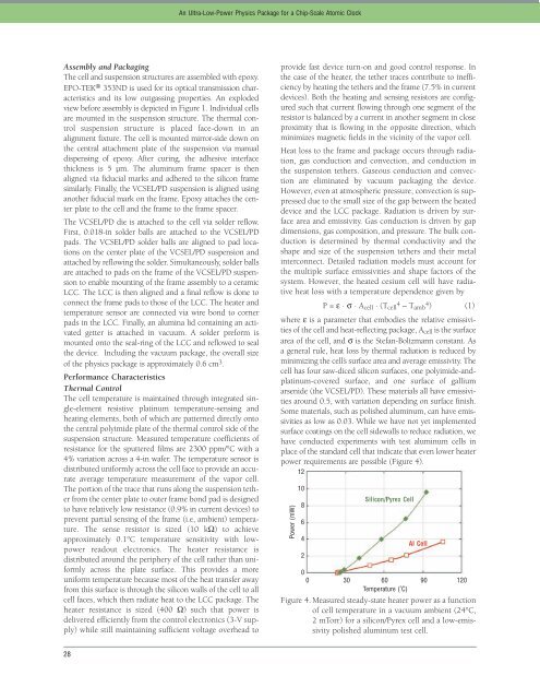
as low as 0.03. While we have not yet implemented<br />
surface coatings on the cell sidewalls to reduce radiation, we<br />
have conducted experiments with test aluminum cells in<br />
place of the standard cell that indicate that even lower heater<br />
power requirements are possible (Figure 4).<br />
12<br />
Power (mW)<br />
10<br />
8<br />
6<br />
4<br />
2<br />
Silicon/Pyrex Cell<br />
AI Cell<br />
0<br />
0 30 60 90 120<br />
Temperature (˚C)<br />
Figure 4. Measured steady-state heater power as a function<br />
of cell temperature in a vacuum ambient (24°C,<br />
2 mTorr) for a silicon/Pyrex cell and a low-emissivity<br />
polished aluminum test cell.


