LTC6945 - Ultralow Noise and Spurious 0.35GHz to 6GHz Integer-N ...
LTC6945 - Ultralow Noise and Spurious 0.35GHz to 6GHz Integer-N ...
LTC6945 - Ultralow Noise and Spurious 0.35GHz to 6GHz Integer-N ...

You also want an ePaper? Increase the reach of your titles
YUMPU automatically turns print PDFs into web optimized ePapers that Google loves.
OPERATION<br />
PHASE/FREQUENCY DETECTOR (PFD)<br />
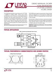
The phase/frequency detec<strong>to</strong>r (PFD), in conjunction with<br />
the charge pump, produces source <strong>and</strong> sink current pulses<br />
proportional <strong>to</strong> the phase difference between the outputs<br />
of the R <strong>and</strong> N dividers. This action provides the necessary<br />
feedback <strong>to</strong> phase-lock the loop, forcing a phase alignment<br />
at the PFD’s inputs. The PFD may be disabled with<br />
the CPRST bit which prevents UP <strong>and</strong> DOWN pulses from<br />
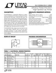
being produced. See Figure 3 for a simplified schematic<br />
of the PFD.<br />
R DIV<br />
N DIV<br />
D Q<br />
RST<br />
D Q<br />
RST<br />
DELAY<br />
CPRST<br />
6945 F03<br />
Figure 3. Simplified PFD Schematic<br />
UP<br />
DOWN<br />
LOCK INDICATOR<br />
The lock indica<strong>to</strong>r uses internal signals from the PFD <strong>to</strong><br />
measure phase coincidence between the R <strong>and</strong> N divider<br />
output signals. It is enabled by setting the LKEN bit in<br />
the serial port register h07, <strong>and</strong> produces both LOCK <strong>and</strong><br />
UNLOCK status flags, available through both the STAT<br />
output <strong>and</strong> serial port register h00.<br />
PHASE<br />
DIFFERENCE<br />
AT PFD<br />
+t LWW<br />
0<br />
–t LWW<br />
UNLOCK FLAG<br />
LOCK FLAG<br />
t = COUNTS/f PFD<br />
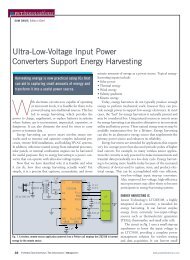
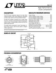
Figure 4. UNLOCK <strong>and</strong> LOCK Timing<br />
<strong>LTC6945</strong><br />
The user sets the phase difference lock window time,<br />
tLWW , for a valid LOCK condition with the LKWIN[1:0]<br />
bits. See Table 3 for recommended settings for different<br />
fPFD frequencies <strong>and</strong> the Applications Information section<br />
for examples.<br />
Table 3. LKWIN[1:0] Programming<br />
LKWIN[1:0] tLWW fPFD 0 3ns >5MHz<br />
1 10ns ≤5MHz<br />
2 30ns ≤1.7MHz<br />
3 90ns ≤550kHz<br />
The PFD phase difference must be less than t LWW for the<br />
COUNTS number of successive counts before the lock<br />
indica<strong>to</strong>r asserts the LOCK flag. The LKCT[1:0] bits found<br />
in register h09 are used <strong>to</strong> set COUNTS depending upon<br />
the application. See Table 4 for LKCT[1:0] programming<br />
<strong>and</strong> the Applications Information section for examples.<br />
Table 4. LKCT[1:0] Programming<br />
LKCT[1:0] COUNTS<br />
0 32<br />
1 128<br />
2 512<br />
3 2048<br />
When the PFD phase difference is greater than tLWW , the<br />
lock indica<strong>to</strong>r immediately asserts the UNLOCK status<br />
flag <strong>and</strong> clears the LOCK flag, indicating an out-of-lock<br />
condition. The UNLOCK flag is immediately de-asserted<br />
when the phase difference is less than tLWW . See Figure 4<br />
for more details.<br />
6945 F04<br />
6945f<br />
11