LTC6945 - Ultralow Noise and Spurious 0.35GHz to 6GHz Integer-N ...
LTC6945 - Ultralow Noise and Spurious 0.35GHz to 6GHz Integer-N ...
LTC6945 - Ultralow Noise and Spurious 0.35GHz to 6GHz Integer-N ...

Create successful ePaper yourself
Turn your PDF publications into a flip-book with our unique Google optimized e-Paper software.
APPLICATIONS INFORMATION<br />
4. Select loop filter components CI <strong>and</strong> CP based on BW<br />
<strong>and</strong> RZ . A reliable loop can be achieved by using the<br />
following equations for the loop capaci<strong>to</strong>rs (in Farads):<br />
3.5<br />
CI =<br />
2 π BW RZ 1<br />
CP =<br />
7 π BW RZ (7)<br />
(8)<br />
LOOP FILTERS USING AN OPAMP<br />
Some VCO tune voltage ranges are greater than the<br />
<strong>LTC6945</strong>’s charge pump voltage range. An active loop filter<br />
using an op amp can increase the tuning voltage range.<br />
To maintain the <strong>LTC6945</strong>’s high performance, care must<br />
be given <strong>to</strong> picking an appropriate op amp.<br />
The op amp input common mode voltage should be biased<br />
within the <strong>LTC6945</strong> charge pump’s voltage range, while<br />
its output voltage should achieve the VCO tuning range.<br />
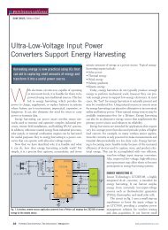
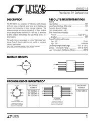
See Figure 16 for an example op amp loop filter.<br />
The op amp’s input bias current is supplied by the charge<br />
pump; minimizing this current keeps spurs related <strong>to</strong> fPFD<br />
low. The input bias current should be less than the charge<br />
pump leakage (found in the Electrical Characteristics section)<br />
<strong>to</strong> avoid increasing spurious products.<br />
I CP<br />
<strong>LTC6945</strong><br />
CP<br />
VCO ±<br />
(f VCO)<br />
VCP +<br />
5k<br />
5k<br />
LOOP FILTER<br />
CP Figure 16. Op Amp Loop Filter<br />
C I<br />
–<br />
+<br />
V CP + /2<br />
47μF<br />
K VCO<br />
R Z<br />
LF(s)<br />
R P2<br />
C P2<br />
6945 F16<br />
<strong>LTC6945</strong><br />
Op amp noise sources are highpass filtered by the PLL<br />
loop filter <strong>and</strong> should be kept at a minimum, as their effect<br />
raises the <strong>to</strong>tal system phase noise beginning near<br />
the loop b<strong>and</strong>width. Choose a low noise op amp whose<br />
input-referred voltage noise is less than the thermal noise<br />
of RZ. Additionally, the gain b<strong>and</strong>width of the op amp<br />
should be at least 15 times the loop b<strong>and</strong>width <strong>to</strong> limit<br />
phase margin degradation. The LT1678 is an op amp that<br />
works very well in most applications.<br />
An additional R-C lowpass filter (formed by RP2 <strong>and</strong> CP2<br />
in Figure 16) connected at the input of the VCO will limit<br />
the op amp noise sources. The b<strong>and</strong>width of this filter<br />
should be placed approximately 15 <strong>to</strong> 20 times the PLL<br />
loop b<strong>and</strong>width <strong>to</strong> limit loop phase margin degradation.<br />
RP2 should be small (preferably much less than RZ) <strong>to</strong><br />
minimize its noise impact on the loop. However, picking<br />
<strong>to</strong>o small of a value can make the op amp unstable as it<br />
has <strong>to</strong> drive the capaci<strong>to</strong>r in this filter.<br />
DESIGN AND PROGRAMMING EXAMPLE<br />
This programming example uses the DC1649. Assume<br />
the following parameters of interest :<br />
fREF = 100MHz at 7dBm in<strong>to</strong> 50Ω<br />
fSTEP = 250kHz<br />
fVCO = 902MHz <strong>to</strong> 928MHz<br />
KVCO = 15MHz/V <strong>to</strong> 21.6MHz/V<br />
fRF = 914MHz<br />
Determining Divider Values<br />
Following the Loop Filter Design algorithm, first determine<br />
all the divider values. Using Equations 2, 3, 4 <strong>and</strong> 5, calculate<br />
the following values:<br />
O = 1<br />
R = 100MHz/250kHz = 400<br />
fPFD = 250kHz<br />
N = 914MHz/250kHz = 3656<br />
6945f<br />
19