LTC6945 - Ultralow Noise and Spurious 0.35GHz to 6GHz Integer-N ...
LTC6945 - Ultralow Noise and Spurious 0.35GHz to 6GHz Integer-N ...
LTC6945 - Ultralow Noise and Spurious 0.35GHz to 6GHz Integer-N ...

Create successful ePaper yourself
Turn your PDF publications into a flip-book with our unique Google optimized e-Paper software.
APPLICATIONS INFORMATION<br />
Measured RF ± s-parameters are shown below in Table<br />
11 <strong>to</strong> aid in the design of impedance matching networks.<br />
Table 11. Single-Ended RF Output Impedance<br />
FREQUENCY (MHz) IMPEDANCE (Ω) S11 (dB)<br />
500 102.8 – j49.7 –6.90<br />
1000 70.2 – j60.1 –6.53<br />
1500 52.4 – j56.2 –6.35<br />
2000 43.6 – j49.2 –6.58<br />
2500 37.9 – j39.6 –7.34<br />
3000 32.7 – j28.2 –8.44<br />
3500 27.9 – j17.8 –8.99<br />
4000 24.3 – j9.4 –8.72<br />
4500 22.2 – j3.3 –8.26<br />
5000 21.6 + j1.9 –8.02<br />
5500 21.8 + j6.6 –7.91<br />
6000 23.1 + j11.4 –8.09<br />
6500 25.7 + j16.9 –8.38<br />
7000 29.3 + j23.0 –8.53<br />
7500 33.5 + j28.4 –8.56<br />
8000 37.9 + j32.6 –8.64<br />
Single-ended impedance matching is accomplished using<br />
the circuit of Figure 18, with component values found in<br />
Table 12. Using smaller inductances than recommended<br />
can cause phase noise degradation, especially at lower<br />
center frequencies.<br />
RF +(–)<br />
RF –(+)<br />
VRF +<br />
V RF +<br />
L C<br />
L C<br />
Figure 18. Single-Ended Output Matching Schematic<br />
C S<br />
C S<br />
50Ω<br />
TO 50Ω<br />
LOAD<br />
6945 F18<br />
<strong>LTC6945</strong><br />
Table 12. Suggested Single-Ended Matching Component Values<br />
fRF (MHz) LC (nH) CS (pF)<br />
350 <strong>to</strong> 1500 180nH 270pF<br />
1000 <strong>to</strong> 5800 68nH 100pF<br />
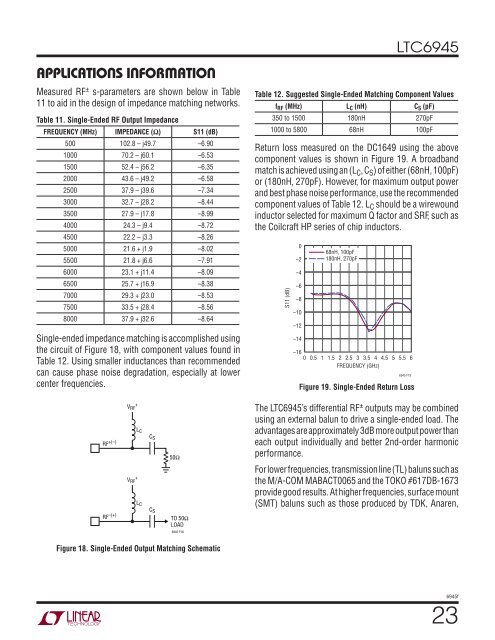
Return loss measured on the DC1649 using the above<br />
component values is shown in Figure 19. A broadb<strong>and</strong><br />
match is achieved using an (LC, CS) of either (68nH, 100pF)<br />
or (180nH, 270pF). However, for maximum output power<br />
<strong>and</strong> best phase noise performance, use the recommended<br />
component values of Table 12. LC should be a wirewound<br />
induc<strong>to</strong>r selected for maximum Q fac<strong>to</strong>r <strong>and</strong> SRF, such as<br />
the Coilcraft HP series of chip induc<strong>to</strong>rs.<br />
S11 (dB)<br />
0<br />
–2<br />
–4<br />
–6<br />
–8<br />
–10<br />
–12<br />
–14<br />
–16<br />
68nH, 100pF<br />
180nH, 270pF<br />
0 0.5 1 1.5 2 2.5 3 3.5 4 4.5 5 5.5 6<br />
FREQUENCY (GHz)<br />
6945 F19<br />
Figure 19. Single-Ended Return Loss<br />
The <strong>LTC6945</strong>’s differential RF ± outputs may be combined<br />
using an external balun <strong>to</strong> drive a single-ended load. The<br />
advantages are approximately 3dB more output power than<br />
each output individually <strong>and</strong> better 2nd-order harmonic<br />
performance.<br />
For lower frequencies, transmission line (TL) baluns such as<br />
the M/A-COM MABACT0065 <strong>and</strong> the TOKO #617DB-1673<br />
provide good results. At higher frequencies, surface mount<br />
(SMT) baluns such as those produced by TDK, Anaren,<br />
6945f<br />
23