

EtherCAN/2 Hardware Manual (PDF-File) - esd electronics, Inc.
EtherCAN/2 Hardware Manual (PDF-File) - esd electronics, Inc.
EtherCAN/2 Hardware Manual (PDF-File) - esd electronics, Inc.

Create successful ePaper yourself
Turn your PDF publications into a flip-book with our unique Google optimized e-Paper software.
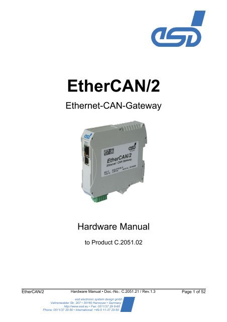
<strong>EtherCAN</strong>/2<br />
Ethernet-CAN-Gateway<br />
<strong>Hardware</strong> <strong>Manual</strong><br />
to Product C.2051.02<br />
<strong>EtherCAN</strong>/2 <strong>Hardware</strong> <strong>Manual</strong> • Doc.-No.: C.2051.21 / Rev.1.3 Page 1 of 52<br />
<strong>esd</strong> electronic system design gmbh<br />
Vahrenwalder Str. 207 • 30165 Hannover • Germany<br />
http://www.<strong>esd</strong>.eu • Fax: 0511/37 29 8-68<br />
Phone: 0511/37 29 80 • International: +49-5 11-37 29 80
N O T E<br />
The information in this document has been carefully checked and is believed to be entirely reliable.<br />
<strong>esd</strong> makes no warranty of any kind with regard to the material in this document, and assumes no<br />
responsibility for any errors that may appear in this document. <strong>esd</strong> reserves the right to make<br />
changes without notice to this, or any of its products, to improve reliability, performance or design.<br />
<strong>esd</strong> assumes no responsibility for the use of any circuitry other than circuitry which is part of a<br />
product of <strong>esd</strong> gmbh.<br />
<strong>esd</strong> does not convey to the purchaser of the product described herein any license under the patent<br />
rights of <strong>esd</strong> gmbh nor the rights of others.<br />
<strong>esd</strong> electronic system design gmbh<br />
Vahrenwalder Str. 207<br />
30165 Hannover<br />
Germany<br />
Phone: +49-511-372 98-0<br />
Fax: +49-511-372 98-68<br />
E-Mail: info@<strong>esd</strong>.eu<br />
Internet: www.<strong>esd</strong>.eu<br />
USA / Canada:<br />
<strong>esd</strong> <strong>electronics</strong> <strong>Inc</strong>.<br />
525 Bernardston Road<br />
Suite 1<br />
Greenfield, MA 01301<br />
USA<br />
Phone: +1-800-732-8006<br />
Fax: +1-800-732-8093<br />
E-mail: us-sales@<strong>esd</strong>-<strong>electronics</strong>.com<br />
Internet: www.<strong>esd</strong>-<strong>electronics</strong>.us<br />
Page 2 of 52 <strong>Hardware</strong> <strong>Manual</strong> • Doc.-No.: C.2051.21 / Rev. 1.3 <strong>EtherCAN</strong>/2
Document file:<br />
Date of print: 2010-05-19<br />
Firmware Version: from Rev. 4.2.0.0<br />
Document History<br />
I:\Texte\Doku\MANUALS\CAN\<strong>EtherCAN</strong>2\Englisch\<strong>EtherCAN</strong>-2_<strong>Hardware</strong>_en_13.odt<br />
The changes in the document listed below affect changes in the hardware as well as changes in<br />
the description of the facts, only.<br />
Revision Chapter Changes versus previous version Date<br />
1.2 all First version of English manual. 2009-11-09<br />
1.3<br />
2.2 LED description updated<br />
4 Updated description for IP- and DHCP configuration<br />
4.2<br />
Updated images<br />
Added description for UPnP<br />
4.2.3 Added description for ELLSI clients<br />
Technical details are subject to change without further notice.<br />
Trademark Notices<br />
2010-05-19<br />
Windows is a registered trademark of Microsoft Corporation in the United States and other countries.<br />
CANopen® is a registered community trademark of CAN in Automation e.V.<br />
UPnP TM is a trademark of the UPnP Implementers Corporation.<br />
All other trademarks, product names, company names or company logos used in this manual are reserved by their<br />
respective owners.<br />
<strong>EtherCAN</strong>/2 <strong>Hardware</strong> <strong>Manual</strong> • Doc.-No.: C.2051.21 / Rev. 1.3 Page 3 of 52
�<br />
Safety Instructions and Conformity<br />
! When working with <strong>EtherCAN</strong>/2 follow the instructions below and read the manual carefully<br />
to protect yourself and the <strong>EtherCAN</strong>/2 from damage.<br />
The <strong>esd</strong> guarantee does not cover damages which result from improper use or disregard of<br />
safety instructions and warnings.<br />
! Do not open the housing of the device. It does not contain any serviceable parts and does<br />
not require any manual configuration of the hardware.<br />
Dismantling the housing by personnel which is not authorized by <strong>esd</strong> causes the loss of all<br />
warranty claims.<br />
! In order to prevent overvoltage damage due to thunder storm, unplug the device from<br />
Ethernet and CAN beforehand.<br />
! Never let liquids get inside the device. Otherwise, electric shocks or short circuits may result.<br />
! Protect the device from dust, moisture and steam. Remove all cables before cleaning. Clean<br />
the device with a slightly moist, lint-free cloth. Cleaning agents or solvents are not suitable.<br />
! Protect the device from shocks and vibrations.<br />
! The device may become warm during normal use. Always allow adequate ventilation around<br />
the device and use care when handling.<br />
! Do not operate the device adjacent to heat sources and do not expose it to unnecessary<br />
thermal radiation. Ensure an ambient temperature of 0°...70 °C.<br />
! Do not use damaged or defective cables to connect the device and follow the CAN wiring<br />
hints at the end of the manual.<br />
! The device is intended for indoor use only.<br />
! The operation of the device in hazardous areas, or areas exposed to potentially explosive<br />
materials is not permitted.<br />
! The operation of the device for medical purposes is prohibited.<br />
! The <strong>EtherCAN</strong>/2 is an industrial product and meets the demands of the EU regulations and<br />
EMC standards printed in the conformity declaration at the end of this manual.<br />
Warning: In a residential, commercial or light industrial environment the <strong>EtherCAN</strong>/2 may<br />
cause radio interferences in which case the user may be required to take<br />
adequate measures.<br />
Page 4 of 52 <strong>Hardware</strong> <strong>Manual</strong> • Doc.-No.: C.2051.21 / Rev. 1.3 <strong>EtherCAN</strong>/2
Table of Contents<br />
1 Overview......................................................................................................................................7<br />
1.1 Safety Instructions.................................................................................................................7<br />
1.2 Service Note..........................................................................................................................7<br />
2 <strong>Hardware</strong> Installation....................................................................................................................8<br />
2.1 Connections...........................................................................................................................8<br />
2.2 LEDs .....................................................................................................................................9<br />
2.2.1 LED Assignment............................................................................................................9<br />
3 Starting Up.................................................................................................................................11<br />
4 Configuration..............................................................................................................................12<br />
4.1 Configuration of the IP Address...........................................................................................12<br />
4.1.1 Configuration via DHCP..............................................................................................12<br />
4.1.1.1 Using a Hostname Instead of the IP Address.......................................................13<br />
4.1.2 Determining IP Address via UPnP...............................................................................13<br />
4.1.3 Configuration via <strong>esd</strong>cp...............................................................................................15<br />
4.2 Web Based Configuration....................................................................................................17<br />
4.2.1 Overview.....................................................................................................................17<br />
4.2.2 Configuration...............................................................................................................18<br />
4.2.2.1 Security.................................................................................................................18<br />
4.2.2.2 Network Settings...................................................................................................19<br />
4.2.2.3 Remote Logging ..................................................................................................23<br />
4.2.2.4 Firmware Update..................................................................................................24<br />
4.2.2.5 Reboot..................................................................................................................26<br />
4.2.3 Status..........................................................................................................................27<br />
4.2.3.1 CAN Statistics.......................................................................................................27<br />
4.2.3.2 Ethernet................................................................................................................28<br />
4.2.3.3 Connected clients.................................................................................................29<br />
4.2.3.4 Alarms and Events................................................................................................30<br />
5 Technical Data...........................................................................................................................31<br />
5.1 General Technical Data.......................................................................................................31<br />
5.2 Microprocessor and Memory................................................................................................31<br />
5.3 CAN Interface......................................................................................................................32<br />
5.4 Ethernet Interface................................................................................................................32<br />
5.5 DIAG, Serial Interface via USB Interface.............................................................................32<br />
5.6 Software...............................................................................................................................33<br />
5.7 Order Information.................................................................................................................34<br />
6 Interfaces and Connector Assignments......................................................................................35<br />
6.1 24 V-Power Supply Voltage.................................................................................................35<br />
6.1.1 Connector Assignment ...............................................................................................35<br />
6.2 CAN.....................................................................................................................................36<br />
6.2.1 Connector Assignment ...............................................................................................37<br />
6.3 24 V and CAN via InRailBus................................................................................................38<br />
6.4 DIAG....................................................................................................................................38<br />
6.4.1 Assignment.................................................................................................................38<br />
7 Correctly Wiring Electrically Isolated CAN Networks..................................................................39<br />
8 CAN-Bus Troubleshooting Guide...............................................................................................43<br />
8.1 Termination..........................................................................................................................43<br />
8.2 CAN_H/CAN_L-Voltage ......................................................................................................44<br />
8.3 Ground.................................................................................................................................44<br />
8.4 CAN Transceiver Resistance Test ......................................................................................45<br />
<strong>EtherCAN</strong>/2 <strong>Hardware</strong> <strong>Manual</strong> • Doc.-No.: C.2051.21 / Rev. 1.3 Page 5 of 52
9 Appendix InRailBus (Option)......................................................................................................46<br />
9.1 Order Information InRailBus Accessories............................................................................46<br />
9.2 Connector Assignment 24V and CAN via InRailBus (Option)..............................................47<br />
9.3 Using InRailBus (Option).....................................................................................................48<br />
9.3.1 Installation of the Module Using InRailBus Connector.................................................48<br />
9.3.2 Connecting Power Supply and CAN Signals to CBX-InRailBus...................................49<br />
9.3.3 Connection of the Power Supply Voltage....................................................................50<br />
9.3.4 Connection of CAN......................................................................................................50<br />
9.4 Remove the CAN-CBX Module from InRailBus....................................................................51<br />
Page 6 of 52 <strong>Hardware</strong> <strong>Manual</strong> • Doc.-No.: C.2051.21 / Rev. 1.3 <strong>EtherCAN</strong>/2
1 Overview<br />
C A N<br />
5-pole<br />
Open style<br />
Connector<br />
In-Rail-Bus<br />
Connector<br />
Combicon 5.08<br />
Power Supply<br />
Electrical Isolation<br />
Physical<br />
CAN<br />
Layer<br />
ISO11898-2<br />
Power Supply<br />
24 V=<br />
Fig. 1: Block circuit diagram<br />
Overview<br />
The <strong>EtherCAN</strong>/2 is an Ethernet-CAN-Gateway equipped with an ARM9 processor, which controls<br />
the data transfer between CAN and Ethernet.<br />
The Ethernet interface is suitable for 10 Mbit/s and 100 Mbit/s networks and can be connected via<br />
an RJ45-socket.<br />
The CAN interface can be connected via a 5-pin Combicon connector.<br />
The interface is in accordance with ISO 11898-2, is electrically isolated and can be used for<br />
transmission rates from 50 kbit/s up to 1 Mbit/s.<br />
The connectors for the Ethernet-, CAN- and serial interface and the status LEDs are located in the<br />
front panel of the top hat rail module and are easily accessible.<br />
The 4-pin Combicon connector for the power supply is located in the case top side, easily<br />
accessible.<br />
1.1 Safety Instructions<br />
When working with <strong>EtherCAN</strong>/2 follow the instructions and information about safety and conformity<br />
(see page 4) and read the manual carefully to protect yourself and the <strong>EtherCAN</strong>/2 from damage.<br />
The intended use is the operation of the <strong>EtherCAN</strong>/2 as Ethernet-CAN-Gateway.<br />
The <strong>esd</strong> guarantee does not cover damages which result from improper use or disregard of safety<br />
instructions and warnings.<br />
1.2 Service Note<br />
DC/DC<br />
Converter<br />
ARM-9<br />
Microcontroller<br />
The <strong>EtherCAN</strong>/2 does not contain any parts that require maintenance by the user.<br />
LEDs<br />
100Base-TX<br />
Transceiver<br />
<strong>EtherCAN</strong>/2 <strong>Hardware</strong> <strong>Manual</strong> • Doc.-No.: C.2051.21 / Rev. 1.3 Page 7 of 52<br />
Flash<br />
SDRAM<br />
Ethernet<br />
RJ45<br />
100BASE-TX<br />
<strong>EtherCAN</strong>
<strong>Hardware</strong> Installation<br />
2 <strong>Hardware</strong> Installation<br />
2.1 Connections<br />
Fig. 2: Connections in operable state<br />
Please refer as well to page 35 for signal assignment of the connectors.<br />
Page 8 of 52 <strong>Hardware</strong> <strong>Manual</strong> • Doc.-No.: C.2051.21 / Rev. 1.3 <strong>EtherCAN</strong>/2
2.2 LEDs<br />
2.2.1 LED Assignment<br />
LEDs of the <strong>EtherCAN</strong>-RJ-45 socket<br />
Fig. 3: Position of the LEDs in the front panel<br />
LED Colour Indication Description<br />
Activity green<br />
Link yellow<br />
off no Ethernet activity<br />
blinking Ethernet activity (reception of Ethernet data)<br />
off no Ethernet connection<br />
on Link Status Ethernet (link to server or hub)<br />
Table 1: Display function of ETH LEDs (RJ45-socket)<br />
<strong>Hardware</strong> Installation<br />
<strong>EtherCAN</strong>/2 <strong>Hardware</strong> <strong>Manual</strong> • Doc.-No.: C.2051.21 / Rev. 1.3 Page 9 of 52
<strong>Hardware</strong> Installation<br />
LEDs C, E, R, P<br />
LED Colour Function Indication Description<br />
C yellow CAN-Status<br />
E red System-<br />
Status<br />
R green Network<br />
P green Power<br />
off Bus-OK<br />
on Bus-OFF<br />
blinking<br />
short on (long off) Bus-Warn<br />
blinking<br />
long on (short off) Bus-Passive<br />
off no error detected<br />
on system start failed<br />
blinking<br />
short on (long off)<br />
blinking<br />
long on (short off)<br />
web-server failure<br />
net configuration failure<br />
(system has set IP address<br />
automatically)<br />
off no <strong>EtherCAN</strong> clients<br />
blinking<br />
short on (long off)<br />
blinking<br />
long on (short off)<br />
off<br />
net configuration active<br />
<strong>EtherCAN</strong> clients connected<br />
no power supply voltage or<br />
hardware error<br />
power supply voltage supplied and<br />
on<br />
hardware initialised correctly.<br />
Table 2: Display function of LEDs<br />
LED-name<br />
in schematic<br />
diagram<br />
LED1A<br />
LED1B<br />
LED1C<br />
LED1D<br />
Page 10 of 52 <strong>Hardware</strong> <strong>Manual</strong> • Doc.-No.: C.2051.21 / Rev. 1.3 <strong>EtherCAN</strong>/2
3 Starting Up<br />
To start up the <strong>EtherCAN</strong>/2 follow the instructions below.<br />
Step<br />
�<br />
Read the safety instructions at the beginning of this document<br />
carefully before you start with the hardware installation!<br />
1. Mount and wire the <strong>EtherCAN</strong>/2 module (power supply voltage,<br />
CAN, Ethernet).<br />
2. Please remember that the CAN bus has to be terminated at both<br />
ends. <strong>esd</strong> offers T-connectors and terminators. Additionally, the<br />
CAN-GND-signal has to be grounded at exactly one point in the<br />
CAN network. Therefore the CAN termination connectors offered by<br />
<strong>esd</strong> have got a grounding contact.<br />
A CAN device with a CAN interface which is not electrically isolated<br />
corresponds to the grounding of the CAN-GND.<br />
see<br />
chapter<br />
Starting Up<br />
see<br />
page<br />
- 4<br />
2.1 8<br />
- -<br />
3. Switch on the 24 V-power supply voltage of the <strong>EtherCAN</strong>/2. - -<br />
4. Assignment of a valid IP address for <strong>EtherCAN</strong>/2.<br />
4a) If the current IP address is known, proceed to step 6. with the<br />
assignment of a fixed IP address and the further<br />
configuration.<br />
4b) If the current IP address is not known, use <strong>esd</strong>cp to detect it<br />
and to assign a fixed IP address. For that purpose at first the<br />
host-driver software has to be installed as described under<br />
step 5.<br />
5. Insert the CAN-driver CD in the appropriate drive of your PC.<br />
Install the <strong>EtherCAN</strong>/2 host-driver software from the CAN-driver CD<br />
on your PC, as described in the manual 'CAN-API Part 2 Installation<br />
Guide' in chapter: 'Installation and Configuration of the <strong>EtherCAN</strong><br />
Module' for the <strong>EtherCAN</strong> module.<br />
The installation will be guided by an installation program (Install<br />
Shield Wizard). The window of the installation program depends on<br />
the Windows operating system installed on your PC.<br />
4.1 12<br />
- -<br />
6. Configure the <strong>EtherCAN</strong>/2 via web browser. 4.2 17<br />
Note: Please note that changes of the configuration generally will<br />
not be effective until a reboot. 4.2.2.5 26<br />
7. Install the host-driver software now as described under step 5., if<br />
not already done.<br />
Configure the host-driver on the Windows PC as described in the<br />
manual 'CAN-API Part 2 Installation Guide' in chapter: 'Installation<br />
and Configuration of the <strong>EtherCAN</strong>-Module' for the <strong>EtherCAN</strong><br />
module.<br />
- -<br />
<strong>EtherCAN</strong>/2 <strong>Hardware</strong> <strong>Manual</strong> • Doc.-No.: C.2051.21 / Rev. 1.3 Page 11 of 52
Configuration<br />
4 Configuration<br />
The following chapter describes the configuration of the <strong>EtherCAN</strong>/2 module in two steps:<br />
1. Assignment of a valid IP address. (If not already known/reachable)<br />
2. Configuration of the other parameters by means of a web browser. (see page 20).<br />
The RJ45-socket has to be connected with the configuring host PC, like in later operation, via a<br />
Twisted-Pair cable with a switch or hub or via a Cross Twisted-Pair cable. The yellow (Link) LED<br />
has to turn on to indicate a correct connection.<br />
4.1 Configuration of the IP Address<br />
First a valid IP address has to be assigned to the <strong>EtherCAN</strong>/2. An IP address is an unique address<br />
for a device, that communicates in a TCP/IP network.<br />
For the configuration it is therefore necessary to configure an unique IP address, which is not<br />
already assigned to another device in the network.<br />
First configuration of the IP address:<br />
In delivery status after switching-on the <strong>EtherCAN</strong>/2 attempts to get assigned an IP address by a<br />
DHCP-server (maximum approx. 2 min.).<br />
In case that the DHCP-server does not assign an IP address to the <strong>EtherCAN</strong>/2, the <strong>EtherCAN</strong>/2<br />
generates an Auto-IP address by itself in the range 169.254.X.X .<br />
To change the assigned IP address it is recommended to use the tool <strong>esd</strong>cp (see page 15).<br />
To enable <strong>esd</strong>cp to find the device, the PC on which <strong>esd</strong>cp runs has to be at least in the same<br />
subnet.<br />
If <strong>esd</strong>cp finds the device, IP address and netmask have to be set like for the later use.<br />
Then (after a Reboot of the <strong>EtherCAN</strong>/2) the <strong>EtherCAN</strong>/2 can be configured by means of a<br />
web browser (see page 17 et seq.).<br />
4.1.1 Configuration via DHCP<br />
For a configuration via DHCP the DHCP-server has to be in the same subnet as the <strong>EtherCAN</strong>/2.<br />
Before usage the DHCP-server possibly has to be configured especially. Please contact your<br />
system administrator for this purpose.<br />
The server assigns to the module a valid IP address, a net mask, a gateway address and the<br />
IP address of a name server. After a successful assignment the <strong>EtherCAN</strong>/2 operates with these<br />
values without reboot.<br />
The IP address which is assigned to the device has to be detected by means of<br />
the logging mechanisms of the DHCP-server.<br />
Further configuration of the network parameters can now be done by means of any web browser,<br />
that is in the same subnet, with the URL http://, as described in chapter: "4.2 Web<br />
based Configuration".<br />
Page 12 of 52 <strong>Hardware</strong> <strong>Manual</strong> • Doc.-No.: C.2051.21 / Rev. 1.3 <strong>EtherCAN</strong>/2
Configuration<br />
Attention!<br />
Without further configuration a DHCP-server might possibly assign another IP address to a device<br />
at every reboot and this only for a specific period. For the driver software on the host-PC it is<br />
necessary, that this IP address is invariable and unchanged for the complete period of operation.<br />
If at every reboot the same IP address shall be assigned to the <strong>EtherCAN</strong>/2 module via DHCP,<br />
the system administrator has to ensure this.<br />
4.1.1.1 Using a Hostname Instead of the IP Address<br />
The DHCP Client of the <strong>EtherCAN</strong>/2 automatically transmits the hostname configured under<br />
Network Settings to the DHCP-Server.<br />
This is subject to some restrictions:<br />
• In addition to the DHCP-server a DNS-server has to be available and both servers must<br />
co-operate accordingly.<br />
• To enable this is task of your system administrator, if necessary - further support by <strong>esd</strong><br />
concerning this matter is not possible.<br />
• The choice of the hostname might be restricted depending on the system and the<br />
DHCP-/DNS-server used: E.g. usually underscores are not allowed. In a test with a DNSserver<br />
a limitation of the length to 15 characters has been found. In another test the<br />
hostname has only been solved correctly, if it contained the domain-suffix. (Independent of<br />
the domain name configured!)<br />
• Each time the <strong>EtherCAN</strong>/2 receives a new IP address from the DHCP-server, all network<br />
connections of the <strong>EtherCAN</strong>/2 are terminated.<br />
Thus <strong>esd</strong> recommends to use a fixed IP address instead!<br />
Standard Hostname<br />
If the hostname is not configured in the web-based configuration, a standard name is generated<br />
containing the serial number.<br />
For example for the serial number "AA001234“ the hostname is: Eth2-001234.<br />
(The same applies for entering "default“ for the hostname in the <strong>esd</strong>cp software.)<br />
4.1.2 Determining IP Address via UPnP<br />
In the state of delivery the <strong>EtherCAN</strong>/2 furthermore operates as an UPnP-device. The IP address<br />
of the <strong>EtherCAN</strong>/2 can not be changed by this, but generally you can easily get to the web based<br />
configuration.<br />
Precondition for this is that UPnP is supported by the operating system used. Furthermore the<br />
IP address used by the <strong>EtherCAN</strong>/2 must be accessible by this computer. (Firewall-settings<br />
concerning UPnP 1 might possibly have to be made.)<br />
1 Standards for UPnP are already defined for the Windows-Firewall (Proceeding after Table 3 automatically<br />
enables these). Otherwise: <strong>Inc</strong>oming connections on UDP Port 1900 and TCP Port 2869 have to be<br />
permitted.<br />
<strong>EtherCAN</strong>/2 <strong>Hardware</strong> <strong>Manual</strong> • Doc.-No.: C.2051.21 / Rev. 1.3 Page 13 of 52
Configuration<br />
Example: Windows XP<br />
Provided that UPnP is enabled, a note is shown when the <strong>EtherCAN</strong>/2 is identified:<br />
Furthermore the symbol of the <strong>EtherCAN</strong>/2 is shown in the window My Network Places:<br />
A double click on the <strong>EtherCAN</strong>/2 icon automatically opens the configuration page in the standard<br />
web-browser.<br />
Enable UPnP under Windows XP<br />
1. Click Start and then click Control Panel<br />
2. In Control Panel, double-click Add or Remove Programs.<br />
3. Click Add/Remove Windows Components.<br />
4. In the Components list, click Networking Services, and then click Details.<br />
5. Select the Universal Plug and Play check box, and then click OK.<br />
6. Click Next, and then click Finish.<br />
Furthermore the service "SSDP-Discovery Service“ has to be enabled.<br />
(See Control Panel → Administration Tools → Services)<br />
Example: Windows Vista / Windows 7<br />
Reference: Microsoft (http://support.microsoft.com/kb/821371/)<br />
Table 3: Enable UPnP under Windows XP<br />
The corresponding settings are generally enabled by default here, and the symbol of the<br />
<strong>EtherCAN</strong>/2 is shown in the window My Network Places (without a note as in Windows XP).<br />
A double click to the icon of the device automatically opens the configuration page in the standard<br />
web-browser.<br />
Additionally there is the context menu entry: "Open CAN Control Panel“, which starts the<br />
configuration software. (Also refer to the software manual: 'CAN-API Part 2, Installation Guide,<br />
chapter: "Installation and Configuration of the <strong>EtherCAN</strong> Module")<br />
Page 14 of 52 <strong>Hardware</strong> <strong>Manual</strong> • Doc.-No.: C.2051.21 / Rev. 1.3 <strong>EtherCAN</strong>/2
4.1.3 Configuration via <strong>esd</strong>cp<br />
Configuration<br />
<strong>esd</strong>cp is a tool to find and configure <strong>esd</strong> devices with Ethernet interface in a LAN. For this a<br />
stateless protocol – using UDP - is used.<br />
To be able to detect devices with Ethernet interface the PC has to be in the same subnet.<br />
Click the button Discover to search for <strong>esd</strong> devices. The detected devices will be shown in the<br />
Device List.<br />
Enable the continuous search for <strong>esd</strong> devices by clicking the Check-Box � Continuous Discovery.<br />
Devices which are no longer available will not automatically be deleted from the list.<br />
To delete the entries of the Device List click the button Clear Device List .<br />
If no DHCP could have been been found and the <strong>EtherCAN</strong>/2 thus has got an IP address in the<br />
range of 169.254.x.x, the PC has to be configured accordingly (only once, for the configuration of<br />
the <strong>EtherCAN</strong>/2).<br />
If the tool <strong>esd</strong>cp has detected the <strong>EtherCAN</strong>/2, at least IP address and subnet mask can/must be<br />
set there. For this double click in the window Property Editor the row IP-address to change the<br />
IP address or the row Netmask to change the netmask.<br />
Now you can open the input field of the selected row also by clicking the button Modify Property .<br />
<strong>EtherCAN</strong>/2 <strong>Hardware</strong> <strong>Manual</strong> • Doc.-No.: C.2051.21 / Rev. 1.3 Page 15 of 52
Configuration<br />
Fig. 5: Modify the IP address via <strong>esd</strong>cp<br />
Enter the IP address in the input field in the column Configured Value.<br />
Enter the Netmask in the same manner.<br />
Activate the check-box � Reset Device for a reboot of the <strong>EtherCAN</strong>/2 after acknowledgement of<br />
the entry, because the changes are not transferred until the device is rebooted.<br />
Confirm the entry of the IP address by clicking the button Apply Changes .<br />
After a request of the password the value entered under Configured Value will then be accepted<br />
as current value and shown under Current Value.<br />
The button Restore Settings deletes the entered values in the field Configured Value. The current<br />
values remain unchanged.<br />
The <strong>esd</strong>cp default password is: <strong>esd</strong><br />
The password can be changed via page "Network settings" of the web-browser.<br />
Page 16 of 52 <strong>Hardware</strong> <strong>Manual</strong> • Doc.-No.: C.2051.21 / Rev. 1.3 <strong>EtherCAN</strong>/2
4.2 Web Based Configuration<br />
Configuration<br />
The <strong>EtherCAN</strong>/2 offers an integrated HTTP-Server, which allows further configuration with a webbrowser.<br />
4.2.1 Overview<br />
A menu is shown on the left side of this program window.<br />
In the menu item Overview the module specific details of the <strong>EtherCAN</strong>/2 are shown. Under<br />
Gateway details you find firmware revision, hardware revision, order number and serial number.<br />
Under Gateway status you find details about the CAN interface of the <strong>EtherCAN</strong>/2.<br />
Fig. 6: Overview<br />
<strong>EtherCAN</strong>/2 <strong>Hardware</strong> <strong>Manual</strong> • Doc.-No.: C.2051.21 / Rev. 1.3 Page 17 of 52
Configuration<br />
4.2.2 Configuration<br />
All settings which can be made under menu item Configuration, are protected by a combination of<br />
user name and password. The default setting at delivery is:<br />
4.2.2.1 Security<br />
User name:<br />
Password:<br />
<strong>esd</strong><br />
<strong>esd</strong><br />
In the Security Setup page you can change the Webserver Username and the Webserver<br />
Password for access protection. These values will be asked for the authentication in the firmware<br />
update as described in the following chapter.<br />
User name and password can be adapted. Usage of special characters and space characters is<br />
not allowed. Pay attention to case sensitivity.<br />
Clicking the button Submit saves the changed data in a non-volatile memory of the <strong>EtherCAN</strong>/2<br />
module. After a reboot the data will become active.<br />
Fig. 7: Enter user name and password<br />
Page 18 of 52 <strong>Hardware</strong> <strong>Manual</strong> • Doc.-No.: C.2051.21 / Rev. 1.3 <strong>EtherCAN</strong>/2
4.2.2.2 Network Settings<br />
The menu item Network Settings contains an overview of the configured values for:<br />
● TCP/IP<br />
● SMTP<br />
● Time Server<br />
● SNMP<br />
● <strong>esd</strong>cp<br />
Fig. 8: Network configuration<br />
Configuration<br />
<strong>EtherCAN</strong>/2 <strong>Hardware</strong> <strong>Manual</strong> • Doc.-No.: C.2051.21 / Rev. 1.3 Page 19 of 52
Configuration<br />
● TCP/IP base configuration<br />
Fig. 9: TCP/IP base configuration<br />
Here the base TCP/IP network parameters can be configured. The current settings of the<br />
parameters are shown in brackets.<br />
At the first time starting up at least the subnet mask and the IP address have to be<br />
adapted to the conditions of the network.<br />
For the communication with other nets, e.g. to access Internet or time server, a Default<br />
Gateway has to be assigned.<br />
The addresses of a nameserver and a NTP-time server can be optionally configured under<br />
Time server configuration. They will be evaluated by the Remote Logging support (see<br />
page 23).<br />
Enable the check box � Use DHCP to assign IP address, gateway and subnet mask via<br />
DHCP. This may cause problems as described in chapter ‘Configuration via DHCP’ (see<br />
page 12).<br />
To use the parameters above (IP address, Subnet Mask, Default Gateway and Nameserver)<br />
the check box must be disabled.<br />
When the checkbox � Enable UPnP is enabled, the <strong>EtherCAN</strong>/2 also acts as an UPnP device.<br />
This is usually only used for an easier discovering when its IP address is unknown, see<br />
chapter: "4.1.2 Determining IP Address via UPnP".<br />
A domain name can be entered in the input box Domain.<br />
TCP/IP Default Parameters<br />
At the first time starting up of the <strong>EtherCAN</strong>/2 the check box � Use DHCP is enabled. Thus<br />
the IP address is per default assigned via the DHCP-Server.<br />
Page 20 of 52 <strong>Hardware</strong> <strong>Manual</strong> • Doc.-No.: C.2051.21 / Rev. 1.3 <strong>EtherCAN</strong>/2
● SMTP configuration<br />
Fig. 10: SMTP configuration<br />
The data such as SMTP server IP, user name, password etc. can be configured here to<br />
forward alarms and events as email to a SMTP server.<br />
Otherwise the configuration of these parameters is not necessary.<br />
If the SMTP server requires a login, the method of the login can be selected under<br />
Auth. method.<br />
Login is selected per default.<br />
● Time Server<br />
Fig. 11: Time server configuration<br />
The NTP-server can be configured in this field.<br />
For correct date and time indication a time server must be configured.<br />
Configuration<br />
To be able to use the Remote Logging-Support these parameters have to be configured.<br />
Without an entry in this field, the calculation of times will restart from 1970-01-01 at 00:00 a.m<br />
with every reboot (power up) of the <strong>EtherCAN</strong>/2 module.<br />
● SNMP<br />
Fig. 12: SNMP configuration<br />
The SNMP configuration is disabled per default.<br />
To use SNMP click the Check-Box � Enable SNMP.<br />
SNMP (Simple Network Management Protocol) is a protocol to control and monitor various<br />
network devices, e.g. router, printer etc.<br />
The <strong>EtherCAN</strong>/2 gateway provides - besides various standard data as e.g. "Uptime" - the data<br />
of the CAN Statistics (see page 27).<br />
<strong>EtherCAN</strong>/2 <strong>Hardware</strong> <strong>Manual</strong> • Doc.-No.: C.2051.21 / Rev. 1.3 Page 21 of 52
Configuration<br />
These data can then be evaluated further by means of corresponding tools (SNMP manager).<br />
An appropriate ".mib" file for this is available in the installation directory of the host-driver.<br />
The SNMP agent of the <strong>EtherCAN</strong>/2 gateway supports the versions 1 and 2c of the SNMP<br />
protocol. The community string is "public".<br />
● <strong>esd</strong>cp<br />
Fig. 13: <strong>esd</strong>cp configuration<br />
To change the <strong>esd</strong>cp password type in the new password in this input field.<br />
Click the button Submit to save the changed data in a non-volatile memory of the <strong>EtherCAN</strong>/2<br />
module. After a reboot the data is enabled.<br />
Page 22 of 52 <strong>Hardware</strong> <strong>Manual</strong> • Doc.-No.: C.2051.21 / Rev. 1.3 <strong>EtherCAN</strong>/2
4.2.2.3 Remote Logging<br />
Configuration<br />
The Remote Logging support of the <strong>EtherCAN</strong>/2 module can be configured and enabled on this<br />
page. The module offers the feature to provide alarms and events not only on the local HTTPserver,<br />
but to forward them as e-mail to a SMTP-Server.<br />
For the configuration of the SMTP parameters refer to SMTP configuration (see page 21).<br />
Fig. 14: Configuration of the Remote Logging<br />
The check box � Log by Email enables/disables the Remote Logging Support.<br />
Use the check boxes � Log Errors, � Log Warnings and � Log Infos to configure which kind of<br />
event should be transmitted as e-mail.<br />
Click the button Submit to save the changed data in a non-volatile memory of the <strong>EtherCAN</strong>/2<br />
module. After a reboot the data is enabled.<br />
<strong>EtherCAN</strong>/2 <strong>Hardware</strong> <strong>Manual</strong> • Doc.-No.: C.2051.21 / Rev. 1.3 Page 23 of 52
Configuration<br />
4.2.2.4 Firmware Update<br />
For an update of the firmware of the <strong>EtherCAN</strong>/2 click the menu item Firmware Update in the<br />
program window.<br />
Fig. 15: Firmware update<br />
The upload of the file is done by means of the web browser. Enter the file name, or click the button<br />
Choose... to select a file.<br />
Acknowledge the entry by clicking the button Submit . The firmware update is started now.<br />
This can take some time. The progress of the updates will be recorded.<br />
Attention ! During firmware update the power supply of the <strong>EtherCAN</strong>/2 must not be cut off,<br />
because the module could get into an inoperable state.<br />
Example print of a firmware update protocol:<br />
Page 24 of 52 <strong>Hardware</strong> <strong>Manual</strong> • Doc.-No.: C.2051.21 / Rev. 1.3 <strong>EtherCAN</strong>/2
Fig. 16: Firmware update protocol (example)<br />
Wait until the protocol about the update is completely finished.<br />
The system will reboot automatically.<br />
Configuration<br />
<strong>EtherCAN</strong>/2 <strong>Hardware</strong> <strong>Manual</strong> • Doc.-No.: C.2051.21 / Rev. 1.3 Page 25 of 52
Configuration<br />
4.2.2.5 Reboot<br />
Click the menu item Reboot in the program window to reboot the system .<br />
Fig. 17: Reboot<br />
To reboot the system click the button Reboot now .<br />
Attention !<br />
The Remote logging settings and the Events Log will be cleared after reboot.<br />
Furthermore the web server will be shut down and all links of the gateway clients will be<br />
disconnected.<br />
Page 26 of 52 <strong>Hardware</strong> <strong>Manual</strong> • Doc.-No.: C.2051.21 / Rev. 1.3 <strong>EtherCAN</strong>/2
4.2.3 Status<br />
4.2.3.1 CAN Statistics<br />
To view the status of the CAN bus click the menu item CAN in the program window.<br />
Fig. 18: Status CAN<br />
Configuration<br />
The values shown are also provided via SNMP (see page 21) and can be evaluated by means of<br />
additional tools.<br />
<strong>EtherCAN</strong>/2 <strong>Hardware</strong> <strong>Manual</strong> • Doc.-No.: C.2051.21 / Rev. 1.3 Page 27 of 52
Configuration<br />
4.2.3.2 Ethernet<br />
The Ethernet status can be displayed by choosing the menu item Ethernet.<br />
On the Ethernet page the current transmission speed (10/100 Mbit/s), the communication mode<br />
(half/full duplex) and the MAC-ID of the <strong>EtherCAN</strong>/2 module are displayed among a number of<br />
statistical parameters of the Ethernet link.<br />
Fig. 19: Ethernet status<br />
Page 28 of 52 <strong>Hardware</strong> <strong>Manual</strong> • Doc.-No.: C.2051.21 / Rev. 1.3 <strong>EtherCAN</strong>/2
4.2.3.3 Connected clients<br />
Click the menu item Connected clients for the status of the <strong>EtherCAN</strong>- and ELLSI clients.<br />
ELLSI Clients<br />
Fig. 20: Connected clients<br />
Configuration<br />
As the total number of connected clients is fixed, the number of table lines is fixed, too. Lines which<br />
contain clients that are not connected (or no longer connected) are displayed in a grey font.<br />
For further information about ELLSI see ELLSI software-manual: ELLSI_Software_<strong>Manual</strong>.pdf.<br />
<strong>EtherCAN</strong>/2 <strong>Hardware</strong> <strong>Manual</strong> • Doc.-No.: C.2051.21 / Rev. 1.3 Page 29 of 52
Configuration<br />
4.2.3.4 Alarms and Events<br />
For this window click the menu item Events.<br />
This page shows the alarms and events from the start up of the <strong>EtherCAN</strong>/2. The events are<br />
classified depending on the severity into the categories Error, Warning and Info. The list will be<br />
deleted at every reboot. During the runtime of the module the occurring events can be transmitted<br />
per e-mail to another PC (see page 23).<br />
For correct date and time indication a time server has to be configured (see page 21). Otherwise<br />
the calculation of times will restart from 1970-01-01 at 00:00 a.m. with every reboot (Power Up) of<br />
the <strong>EtherCAN</strong>/2 module.<br />
Fig. 21: Alarms and Events<br />
Page 30 of 52 <strong>Hardware</strong> <strong>Manual</strong> • Doc.-No.: C.2051.21 / Rev. 1.3 <strong>EtherCAN</strong>/2
5 Technical Data<br />
5.1 General Technical Data<br />
Power nominal voltage: typical: 24 V/DC, (min.: 18 V, max.: 32 V)<br />
current consumption: (24 V, 20 °C): typical: 100 mA<br />
Connectors<br />
24V<br />
CAN<br />
ETH<br />
InRailBus<br />
24 V-power supply voltage (X1, 4-pin COMBICONconnector<br />
with spring-cage connection)<br />
CAN bus interface<br />
(X2, 5-pin Phoenix Contact MC 1,5/5-GF-3,81)<br />
Ethernet interface (X5, 8-pin RJ45-socket)<br />
Technical Data<br />
CAN bus interface and power supply voltage via InRailBus<br />
(X6, 5-pin TBUS-connector, accessories)<br />
The following interface is for manufacturing purposes:<br />
DIAG DIAG interface (X4, USB-connector type B)<br />
Temperature range 0 °C ... 70 °C ambient temperature<br />
Humidity max. 90 %, non-condensing<br />
Dimensions width: 22 mm, height: 112 mm, depth: 113 mm<br />
Weight 130 g<br />
5.2 Microprocessor and Memory<br />
Table 4: General technical data<br />
CPU ARM9-Processor, 200 MHz, AT91SAM9263<br />
Data Flash 1 MB<br />
NAND Flash 256 MB<br />
SDRAM 32 MB<br />
Table 5: Microprocessor and Memory<br />
<strong>EtherCAN</strong>/2 <strong>Hardware</strong> <strong>Manual</strong> • Doc.-No.: C.2051.21 / Rev. 1.3 Page 31 of 52
Technical Data<br />
5.3 CAN Interface<br />
Number of CAN-Interfaces 1 x CAN<br />
CAN controller integrated in CPU<br />
CAN protocol according to ISO 11898-1<br />
Physical Interface<br />
High-Speed physical Layer according to ISO 11898-2,<br />
Transmission rate programmable up to 1 Mbit/s<br />
Bus termination Terminating resistor has to be set externally, if required.<br />
Electrical isolation<br />
500 V (effective)<br />
between CAN potential and module-system-potential<br />
with pollution degree 1,<br />
via optocoupler and DC/DC converter<br />
Connector CAN, 5-pin COMBICON (X2)<br />
5.4 Ethernet Interface<br />
Number of the interfaces 1<br />
Table 6: Data of the CAN interface<br />
Bit rate 100BASE-TX, 100 Mbit/s<br />
Connection Twisted Pair (compatible to IEEE 802.3), 100BASE-TX,<br />
Electrical isolation via transformer<br />
Connector RJ-45-socket with integrated LEDs in the front panel (X5)<br />
Table 7: Data of the Ethernet interface<br />
5.5 DIAG, Serial Interface via USB Interface<br />
Type USB, for manufacturing purposes only<br />
USB specification USB 2.0 Full Speed (12 Mbit/s)<br />
Connector DIAG (X4), USB-connector type-B<br />
Table 8: Data of the DIAG interface<br />
Page 32 of 52 <strong>Hardware</strong> <strong>Manual</strong> • Doc.-No.: C.2051.21 / Rev. 1.3 <strong>EtherCAN</strong>/2
5.6 Software<br />
Technical Data<br />
The complete local firmware is stored in the internal flash and can be updated as required. The<br />
<strong>EtherCAN</strong>/2 module can be configured by means of a web-browser.<br />
For the operation of the Ethernet-CAN-Gateways as virtual CAN adapter specific drivers are<br />
currently available for Windows XP, Windows Vista and Linux. These allow the usage of the<br />
complete CAN-SDK incl. the monitor-programs CANreal, if available on the host platform.<br />
The installation of the host software is described in the manual ‘CAN-API Part 2 Installation Guide’.<br />
Bootloader U-Boot<br />
License information<br />
Operating system Linux, Kernel 2.6.x<br />
This product uses the open source-bootloader "Das U-Boot". The U-<br />
Boot-source code is released under the terms of the GNU Public<br />
License (GPL).<br />
The complete text of the license is contained in the <strong>esd</strong>-document<br />
"3rd Party Licensor Notice" as part of the product documentation.<br />
<strong>esd</strong> provides the complete bootloader-source code on request.<br />
<strong>esd</strong> strives to restore all changes on the bootloader into the official<br />
sources.<br />
The homepage of the U-Boot project is:<br />
http://www.denx.de/wiki/U-Boot.<br />
Adaptation Driver and API-functions are optimized for this system<br />
License information<br />
This product uses the operating system "Linux".<br />
The Linux-source code is released under the terms of the GNU Public<br />
License (GPL).<br />
The complete text of the license is contained in the <strong>esd</strong>-document<br />
"3rd Party Licensor Notice" as part of the product documentation.<br />
<strong>esd</strong> provides the complete operating system source code on request.<br />
<strong>EtherCAN</strong>/2 <strong>Hardware</strong> <strong>Manual</strong> • Doc.-No.: C.2051.21 / Rev. 1.3 Page 33 of 52
Technical Data<br />
5.7 Order Information<br />
Type Description Order No.<br />
<strong>EtherCAN</strong>/2 Ethernet-CAN-Gateway C.2051.02<br />
<strong>EtherCAN</strong>/2-S7<br />
Ethernet-CAN-Gateway module inclusive S7-example<br />
project with function block to connect a S7-300/400 via<br />
Industrial Ethernet/UDP<br />
C.2051.07<br />
CAN-DRV-LCD Object licence for Windows and Linux incl. CD-ROM C.1101.02<br />
<strong>Manual</strong>s:<br />
<strong>EtherCAN</strong>/2-ME<br />
<strong>EtherCAN</strong>/2 manual in English<br />
(this manual)<br />
C.2051.21<br />
<strong>EtherCAN</strong>/2-MD <strong>EtherCAN</strong>/2 manual in German C.2051.20<br />
CAN-API-ME<br />
Software manual for the Host-software drivers in<br />
English<br />
C.2001.21<br />
CANopen-ME CANopen manuals C.2002.21<br />
Table 9: Order information<br />
Page 34 of 52 <strong>Hardware</strong> <strong>Manual</strong> • Doc.-No.: C.2051.21 / Rev. 1.3 <strong>EtherCAN</strong>/2
6 Interfaces and Connector Assignments<br />
6.1 24 V-Power Supply Voltage<br />
Interfaces and Connector Assignments<br />
The power supply voltage can be fed via connector X1 or optional via InRailBus (connector<br />
assignment see page 38).<br />
6.1.1 Connector Assignment<br />
Device socket: Phoenix Contact MSTBO 2,5/4-G1L-KMGY<br />
Line connector: Phoenix Contact FKCT 2,5/4-ST, 5.0 mm pitch,<br />
spring cage connection,<br />
Phoenix Contact order No.: 19 21 90 0 (included in the scope of delivery)<br />
Pin Position:<br />
Pin Assignment:<br />
Pin 1 2 3 4<br />
Labelling of<br />
the <strong>EtherCAN</strong>/2<br />
Signal<br />
• • M P<br />
Do not<br />
connect!<br />
Please refer to the connecting diagram page 8.<br />
�<br />
Signal description:<br />
Do not<br />
connect!<br />
M24<br />
(GND)<br />
P24<br />
(+24 V)<br />
Attention!<br />
It is not permissible to feed through the power supply voltage through the connector<br />
X1 and to supply the power supply voltage to another CAN module station!<br />
A feed through of the +24V power supply voltage can cause damage on the modules.<br />
P24... power supply voltage +24 V ± 10 %<br />
M24... reference potential<br />
<strong>EtherCAN</strong>/2 <strong>Hardware</strong> <strong>Manual</strong> • Doc.-No.: C.2051.21 / Rev. 1.3 Page 35 of 52
Interfaces and Connector Assignments<br />
6.2 CAN<br />
The differential CAN Bus signals are electrically isolated from the other signals via dual digital<br />
isolator and DC/DC-converter.<br />
3.5V<br />
GND<br />
DC/DC<br />
+<br />
3.5V<br />
5V<br />
- -<br />
CAN_Tx<br />
CAN_Rx<br />
3.5V<br />
+<br />
Digital Isolator<br />
I1<br />
O2<br />
VDD1<br />
GND1<br />
CAN_GND<br />
O1<br />
I2<br />
VDD2<br />
GND2<br />
100nF<br />
+5V<br />
100nF<br />
VC120605D150<br />
CAN Transceiver<br />
TX<br />
VDD<br />
R/GND<br />
Fig. 22: CAN-Interface<br />
The CAN interface can be connected via CAN connector (X2) or optional via InRailBus, see order<br />
information in the appendix (page 47).<br />
Page 36 of 52 <strong>Hardware</strong> <strong>Manual</strong> • Doc.-No.: C.2051.21 / Rev. 1.3 <strong>EtherCAN</strong>/2<br />
BUSL<br />
RX BUSH<br />
GND<br />
Funktionserde<br />
(FE)<br />
+24 V<br />
GND<br />
CAN_GND<br />
X5<br />
InRailBus<br />
CAN_H<br />
CAN_L<br />
FE<br />
CAN_L<br />
CAN_H<br />
CAN_GND<br />
Shield<br />
X2<br />
4<br />
5<br />
3<br />
1<br />
2<br />
S (Verbindung<br />
zu Hutschiene)<br />
MC 1,5/5-GF-3,81<br />
2<br />
4<br />
1<br />
3
6.2.1 Connector Assignment<br />
Interfaces and Connector Assignments<br />
Device connector : Phoenix Contact MC 1,5/5-GF-3,81<br />
Line connector: Phoenix Contact FK-MCP 1,5/5-STF-3,81, spring-cage connection<br />
Phoenix Contact Order No.: 1851261 (included in delivery)<br />
Signal description:<br />
Pin Position: Pin Assignment:<br />
(device connector view)<br />
1<br />
2<br />
3<br />
4<br />
5<br />
Pin Signal<br />
1 CAN_GND<br />
2 CAN_L<br />
3 Shield<br />
4 CAN_H<br />
5 -<br />
CAN_L, CAN_H ... CAN signals<br />
CAN_GND ... reference potential of the local CAN physical layer<br />
Shield ... pin for line shield connection (using hat rail mounting direct contact to the<br />
mounting rail potential)<br />
- ... not connected<br />
Recommendation of an adapter cable from 5-pin COMBICON (here line connector<br />
FK-MCP1,5/5-STF_3,81 with spring-cage-connection) to 9-pin DSUB:<br />
The assignment of the<br />
5-pin Mini- COMBICON<br />
is designed according to<br />
CiA DR-303 Part 1<br />
The assignment of the 9pin<br />
DSUB-connector is<br />
designed according to<br />
CiA DS-102.<br />
<strong>EtherCAN</strong>/2 <strong>Hardware</strong> <strong>Manual</strong> • Doc.-No.: C.2051.21 / Rev. 1.3 Page 37 of 52
Interfaces and Connector Assignments<br />
6.3 24 V and CAN via InRailBus<br />
Power supply voltage and CAN can optionally be fed via InRailBus.<br />
Use the mounting-rail bus connector of the CBX-InRailBus for the connection via the InRailBus,<br />
see order information in the appendix (page 46).<br />
Take notice of the instructions for connecting power supply and CAN signals via InRailBus in the<br />
appendix!<br />
6.4 DIAG<br />
The serial diagnosis interface DIAG does not fulfil a function and is only used for manufacturing<br />
purposes.<br />
6.4.1 Assignment<br />
Note: The module may only be operated with USB nets with USB interfaces with versions<br />
1.1 or 2.0!<br />
Operability can only be guaranteed for these USB interfaces.<br />
Pin Position:<br />
Pin Assignment:<br />
Pin Signal<br />
1<br />
V BUS<br />
2 D-<br />
3 D+<br />
4 GND<br />
Shell Shield<br />
USB socket (type B)<br />
2<br />
3 4<br />
Page 38 of 52 <strong>Hardware</strong> <strong>Manual</strong> • Doc.-No.: C.2051.21 / Rev. 1.3 <strong>EtherCAN</strong>/2<br />
1
Correctly Wiring Electrically Isolated CAN Networks<br />
7 Correctly Wiring Electrically Isolated CAN Networks<br />
Generally all instructions applying for wiring regarding an electromagnetic compatible installation,<br />
wiring, cross sections of wires, material to be used, minimum distances, lightning protection, etc.<br />
have to be followed.<br />
The following general rules for the CAN wiring must be followed:<br />
1 A suitable type of wire (wave impedance approx. 120 Ω ±10%) with an adequate wire cross<br />
section has to be used and the voltage loss in the wire has to be considered!<br />
2 A CAN data wire requires two twisted wires and a wire to conduct the reference potential<br />
(CAN_GND)!<br />
For this the shield of the wire should be used!<br />
3 The reference potential CAN_GND has to be connected to the earth potential (PE) at one point.<br />
Exactly one connection to earth has to be established!<br />
4 A CAN net must not branch (exception: short stub lines) and has to be terminated by the wave<br />
impedance of the wire (generally 120 Ω ±10%) at both ends (between the signals CAN_L and<br />
CAN_H)!<br />
5 Stub lines have to kept as short as possible (l < 0.3 m)!<br />
6 The bit rate has to be adapted to the wire length.<br />
7 CAN wires should not be laid directly next to disturbing sources. If this cannot be avoided, double<br />
shielded wires are preferable.<br />
8 When using double shielded wires the external shield has to be connected to the earth potential<br />
(PE) at one point. There must be not more than one connection to earth.<br />
Wire structure Signal assignment of wire and connection of earthing and terminator<br />
CAN_H<br />
CAN_L<br />
CAN_GND<br />
Shielded wire with<br />
transposed wires<br />
120 Ohm<br />
CAN wire with connectors<br />
DSUB9 connector<br />
DSUB9 connector<br />
(female or male)<br />
pin designation<br />
CAN_GND<br />
(at wire shield)<br />
(female or male)<br />
pin designation<br />
1<br />
2<br />
n.c.<br />
CAN_L<br />
n.c. 1<br />
2<br />
3<br />
3<br />
4 n.c.<br />
n.c. 4<br />
5 n.c.<br />
n.c. 5<br />
6<br />
7<br />
n.c.<br />
CAN_H<br />
n.c. 6<br />
7<br />
8 n.c.<br />
n.c. 8<br />
9 n.c.<br />
n.c. 9<br />
connector case n.c.<br />
n.c. connector case<br />
n.c. = not connected<br />
Figure.: Structure and connection of Wire<br />
<strong>EtherCAN</strong>/2 <strong>Hardware</strong> <strong>Manual</strong> • Doc.-No.: C.2051.21 / Rev. 1.3 Page 39 of 52<br />
120 Ohm<br />
earth (PE)
Correctly Wiring Electrically Isolated CAN Networks<br />
Cabling<br />
� for devices which have only one CAN connector per net use T-connector and stub (shorter<br />
than 0.3 m) (available as accessory)<br />
Figure: Example for correct wiring (when using single shielded wires)<br />
Terminal Resistance<br />
� use external terminator, because this can later be found again more easily!<br />
� 9-pin DSUB-terminator with male and female contacts and earth terminal are available as<br />
accessories<br />
Earthing<br />
� CAN_GND has to be conducted in the CAN wire, because the individual <strong>esd</strong> modules are<br />
electrically isolated from each other!<br />
� CAN_GND has to be connected to the earth potential (PE) at exactly one point in the net!<br />
� each CAN user without electrically isolated interface works as an earthing, therefore: do not<br />
connect more than one user without potential separation!<br />
� Earthing can e.g. be made at a connector<br />
Page 40 of 52 <strong>Hardware</strong> <strong>Manual</strong> • Doc.-No.: C.2051.21 / Rev. 1.3 <strong>EtherCAN</strong>/2
Wire Length<br />
Correctly Wiring Electrically Isolated CAN Networks<br />
� Optical couplers are delaying the CAN signals. By using fast digital isolators and testing each<br />
board at 1 Mbit/s, <strong>esd</strong> modules typically reach a wire length of 37 m at 1 Mbit/s within a closed<br />
net without impedance disturbances like e.g. longer stub.<br />
Bit rate<br />
[kbit/s]<br />
1000<br />
800<br />
666.6<br />
500<br />
333.3<br />
250<br />
166<br />
125<br />
100<br />
66.6<br />
50<br />
33.3<br />
20<br />
12.5<br />
10<br />
Typical values of reachable<br />
wire length with <strong>esd</strong><br />
interface l max [m]<br />
37<br />
59<br />
80<br />
130<br />
180<br />
270<br />
420<br />
570<br />
710<br />
1000<br />
1400<br />
2000<br />
3600<br />
5400<br />
7300<br />
CiA recommendations<br />
(07/95) for reachable wire<br />
lengths l min [m]<br />
25<br />
50<br />
-<br />
100<br />
-<br />
250<br />
-<br />
500<br />
650<br />
-<br />
1000<br />
-<br />
2500<br />
-<br />
5000<br />
Table: Reachable wire lengths depending on the bit rate when using <strong>esd</strong>-CAN interfaces<br />
<strong>EtherCAN</strong>/2 <strong>Hardware</strong> <strong>Manual</strong> • Doc.-No.: C.2051.21 / Rev. 1.3 Page 41 of 52
Correctly Wiring Electrically Isolated CAN Networks<br />
Examples for CAN Wires<br />
Manufacturer Type of wire<br />
U.I. LAPP GmbH<br />
Schulze-Delitzsch-Straße 25<br />
70565 Stuttgart<br />
www.lappkabel.de<br />
ConCab GmbH<br />
Äußerer Eichwald<br />
74535 Mainhardt<br />
www.concab.de<br />
e.g.<br />
UNITRONIC ®-BUS CAN UL/CSA (UL/CSA approved)<br />
UNITRONIC ®-BUS-FD P CAN UL/CSA (UL/CSA approved)<br />
e. g.<br />
BUS-PVC-C (1 x 2 x 0,22 mm²) Order No.: 93 022 016 (UL appr.)<br />
BUS-Schleppflex-PUR-C (1 x 2 x 0,25 mm²) Order No.: 94 025 016 (UL appr.)<br />
i Note: Completely configured CAN wires can be ordered from <strong>esd</strong>.<br />
Page 42 of 52 <strong>Hardware</strong> <strong>Manual</strong> • Doc.-No.: C.2051.21 / Rev. 1.3 <strong>EtherCAN</strong>/2
8 CAN-Bus Troubleshooting Guide<br />
CAN-Bus Troubleshooting Guide<br />
The CAN-Bus Troubleshooting Guide is a guide to find and eliminate the most frequent hardwareerror<br />
causes in the wiring of CAN-networks.<br />
120 �<br />
CAN_H<br />
CAN_L<br />
CAN_GND<br />
8.1 Termination<br />
Fig. : Simplified diagram of a CAN network<br />
The termination is used to match impedance of a node to the impedance of the transmission line<br />
being used. When impedance is mismatched, the transmitted signal is not completely absorbed by<br />
the load and a portion is reflected back into the transmission line. If the source, transmission line<br />
and load impedance are equal these reflections are eliminated. This test measures the series<br />
resistance of the CAN data pair conductors and the attached terminating resistors.<br />
To test it, please<br />
1. Turn off all power supplies of the attached CAN nodes.<br />
2. Measure the DC resistance between CAN_H and CAN_L at the middle and ends of<br />
the network 1<br />
(see figure above).<br />
The measured value should be between 50 Ω and 70 Ω. The measured value should be nearly the<br />
same at each point of the network.<br />
If the value is below 50 Ω, please make sure that:<br />
- there is no short circuit between CAN_H and CAN_L wiring<br />
- there are not more than two terminating resistors<br />
- the nodes do not have faulty transceivers.<br />
CAN_H<br />
CAN_L<br />
CAN_GND<br />
2 3<br />
If the value is higher than 70 Ω, please make sure that:<br />
- there are no open circuits in CAN_H or CAN_L wiring<br />
- your bus system has two terminating resistors (one at each end) and that they are 120 Ω<br />
each.<br />
<strong>EtherCAN</strong>/2 <strong>Hardware</strong> <strong>Manual</strong> • Doc.-No.: C.2051.21 / Rev. 1.3 Page 43 of 52<br />
V<br />
V<br />
120 �<br />
Ω<br />
1
CAN-Bus Troubleshooting Guide<br />
8.2 CAN_H/CAN_L-Voltage<br />
Each node contains a CAN transceiver that outputs differential signals. When the network<br />
communication is idle the CAN_H and CAN_L voltages are approximately 2.5 volts. Faulty<br />
transceivers can cause the idle voltages to vary and disrupt network communication.<br />
To test for faulty transceivers, please<br />
1. Turn on all supplies.<br />
2. Stop all network communication.<br />
3. Measure the DC voltage between CAN_H and GND<br />
(see figure above).<br />
4. Measure the DC voltage between CAN_L and GND<br />
(see figure above).<br />
Normally the voltage should be between 2.0 V and 4.0 V.<br />
If it is lower than 2.0 V or higher than 4.0 V, it is possible that one or more nodes have faulty<br />
transceivers. For a voltage lower than 2.0 V please check CAN_H and CAN_L conductors for<br />
continuity. For a voltage higher than 4.0 V, please check for excessive voltage.<br />
To find the node with a faulty transceiver please test the CAN transceiver resistance (see chapter:<br />
“8.4 CAN Transceiver-Resistance Test”).<br />
8.3 Ground<br />
The shield of the CAN network has to be grounded at only one location. This test will indicate if the<br />
shielding is grounded in several places. To test it, please<br />
1.<br />
2.<br />
3.<br />
Disconnect the shield wire (Shield)<br />
from the ground.<br />
Measure the DC resistance<br />
between Shield and ground (see<br />
picture on the right hand).<br />
Connect Shield wire to ground.<br />
Fig.: Simplified schematic diagram of ground test measurement<br />
The resistance should be higher than 1 MΩ. If it is lower, please search for additional grounding of<br />
the shield wires.<br />
Page 44 of 52 <strong>Hardware</strong> <strong>Manual</strong> • Doc.-No.: C.2051.21 / Rev. 1.3 <strong>EtherCAN</strong>/2<br />
3<br />
2<br />
CAN_H<br />
CAN_L<br />
CAN_GND<br />
Ω<br />
>1M�
8.4 CAN Transceiver Resistance Test<br />
CAN-Bus Troubleshooting Guide<br />
CAN transceivers have one circuit that controls CAN_H and another circuit that controls CAN_L.<br />
Experience has shown that electrical damage to one or both of the circuits may increase the<br />
leakage current in these circuits.<br />
To measure the current leakage through the CAN circuits, please use an resistance measuring<br />
device and:<br />
1. Switch off the node 4<br />
(see figure below).<br />
and disconnect it from the network.<br />
2. Measure the DC resistance between CAN_H and CAN_GND<br />
(see figure below).<br />
3. Measure the DC resistance between CAN_L and CAN_GND<br />
(see figure below).<br />
Normally the resistance should be between 1 MΩ and 4 MΩ or higher. If it is lower than this range,<br />
the CAN transceiver is probably faulty.<br />
CAN-node<br />
CAN-<br />
Transceiver<br />
CAN_H<br />
CAN_L<br />
CAN_GND<br />
Power<br />
4<br />
Disconnect<br />
Power !<br />
5 6<br />
Fig.: Simplified diagram of a CAN node<br />
<strong>EtherCAN</strong>/2 <strong>Hardware</strong> <strong>Manual</strong> • Doc.-No.: C.2051.21 / Rev. 1.3 Page 45 of 52<br />
Ω<br />
Ω<br />
5<br />
6<br />
4<br />
Disconnect<br />
CAN !
Appendix InRailBus (Option)<br />
9 Appendix InRailBus (Option)<br />
9.1 Order Information InRailBus Accessories<br />
Accessories<br />
Type Properties Order No.<br />
CAN-CBX-TBUS<br />
CAN-CBX-TBUS-<br />
Connector<br />
CAN-CBX-TBUS-<br />
Connection adapter<br />
Mounting-rail bus connector of the CBX-<br />
InRailBus for CAN-CBX modules<br />
(order separately)<br />
Terminal plug of the CBX-InRailBus for the<br />
connection of the +24V power supply voltage<br />
and the CAN interface<br />
Female type<br />
Terminal plug of the CBX-InRailBus for the<br />
connection of the +24V power supply voltage<br />
and the CAN-Interface<br />
Male type<br />
Table 10: Order Information<br />
C.3000.01<br />
C.3000.02<br />
C.3000.03<br />
Page 46 of 52 <strong>Hardware</strong> <strong>Manual</strong> • Doc.-No.: C.2051.21 / Rev. 1.3 <strong>EtherCAN</strong>/2
Appendix InRailBus (Option)<br />
9.2 Connector Assignment 24V and CAN via InRailBus (Option)<br />
Connector type: Mounting-rail bus connector of the CBX-InRailBus<br />
Phoenix Contact ME 22,5 TBUS 1,5/5-ST-3,81 KMGY<br />
Signal Description:<br />
Connector View:<br />
Pin Assignment:<br />
Pin Signal<br />
5 M24 (GND)<br />
4 P24 (+24 V)<br />
3 CAN_GND<br />
2 CAN_L<br />
1 CAN_H<br />
S FE (PE_GND)<br />
CAN_L,<br />
CAN_H ... CAN signals<br />
CAN_GND ... reference potential of the local CAN-Physical layers<br />
P24... power supply voltage +24 V<br />
M24... reference potential<br />
FE... functional earth contact (EMC) (connected to mounting rail potential)<br />
<strong>EtherCAN</strong>/2 <strong>Hardware</strong> <strong>Manual</strong> • Doc.-No.: C.2051.21 / Rev. 1.3 Page 47 of 52
Appendix InRailBus (Option)<br />
9.3 Using InRailBus (Option)<br />
i<br />
Note:<br />
This chapter describes the installation of the module using InRailBus for CAN-CBXmodules.<br />
For the <strong>EtherCAN</strong>/2 module the following points apply accordingly .<br />
9.3.1 Installation of the Module Using InRailBus Connector<br />
If the CAN bus signals and the power supply voltage shall be fed via the InRailBus, please proceed<br />
as follows:<br />
Figure. 23: Mounting rail with bus connector<br />
1. Position the InRailBus connector on the mounting rail and snap it onto the mounting rail<br />
using slight pressure. Plug the bus connectors together to contact the communication and<br />
power signals (in parallel with one). The bus connectors can be plugged together before or<br />
after mounting the CAN-CBX modules.<br />
2. Place the CAN-CBX module with the DIN rail guideway on the top edge of the mounting rail.<br />
Figure. 24: Mounting CAN-CBX modules<br />
Page 48 of 52 <strong>Hardware</strong> <strong>Manual</strong> • Doc.-No.: C.2051.21 / Rev. 1.3 <strong>EtherCAN</strong>/2
Appendix InRailBus (Option)<br />
3. Swivel the CAN-CBX module onto the mounting rail in pressing the module downwards<br />
according to the arrow as shown in figure 23. The housing is mechanically guided by the DIN<br />
rail bus connector.<br />
4. When mounting the CAN-CBX module the metal foot catch snaps on the bottom edge of the<br />
mounting rail. Now the module is mounted on the mounting rail and connected to the<br />
InRailBus via the bus connector. Connect the bus connectors and the InRailBus, if not<br />
already done.<br />
Figure. 25: Mounted CAN-CBX module<br />
9.3.2 Connecting Power Supply and CAN Signals to CBX-InRailBus<br />
To connect the power supply and the CAN-signals via the InRailBus, a terminal plug is needed.<br />
The terminal plug is not included in delivery and must be ordered separately (order no.: C.3000.02,<br />
see order information for InRailBus Accessories, page 46).<br />
Figure. 26: Mounting rail with InRailBus and terminal plug<br />
Plug the terminal plug into the socket on the right of the mounting-rail bus connector of the<br />
InRailBus, as described in Figure 26. Then connect the CAN interface and the power supply<br />
voltage via the terminal plug.<br />
<strong>EtherCAN</strong>/2 <strong>Hardware</strong> <strong>Manual</strong> • Doc.-No.: C.2051.21 / Rev. 1.3 Page 49 of 52
Appendix InRailBus (Option)<br />
9.3.3 Connection of the Power Supply Voltage<br />
�<br />
Attention!<br />
It is not permissible to feed through the power supply voltage through the CBX<br />
station and to supply it to another CBX station via 24V connector! A feed through<br />
of the +24 V power supply voltage can cause damage on the CBX modules.<br />
Figure. 27: Connecting the power supply voltage to the CAN-CBX station<br />
9.3.4 Connection of CAN<br />
Figure. 28: Connecting the CAN signals to the CAN-CBX station<br />
Generally the CAN signals can be fed via the CAN connector of the first CAN-CBX module of the<br />
CBX station. The signals are then connected through the CAN-CBX station via the InRailBus. To<br />
lead through the CAN signals the CAN bus connector of the last CAN-CBX module of the CAN-<br />
CBX station has to be used. The CAN connectors of the CAN-CBX modules which are not at the<br />
ends of the CAN-CBX station must not be connected to the CAN bus, because this would cause<br />
incorrect branching.<br />
A bus termination must be connected to the CAN connector of the CAN-CBX module at the end of<br />
the CBX-InRailBus (see Fig. 25), if the CAN bus ends there.<br />
Page 50 of 52 <strong>Hardware</strong> <strong>Manual</strong> • Doc.-No.: C.2051.21 / Rev. 1.3 <strong>EtherCAN</strong>/2
9.4 Remove the CAN-CBX Module from InRailBus<br />
If the CAN-CBX module is connected to the InRailBus please proceed as follows:<br />
Appendix InRailBus (Option)<br />
Release the module from the mounting rail in moving the foot catch (see Fig. 24) downwards (e.g.<br />
with a screwdriver). Now the module is detached from the bottom edge of the mounting rail and<br />
can be removed.<br />
i<br />
Note:<br />
It is possible to remove individual devices from the whole without interrupting the<br />
InRailBus connection, because the contact chain will not be interrupted.<br />
<strong>EtherCAN</strong>/2 <strong>Hardware</strong> <strong>Manual</strong> • Doc.-No.: C.2051.21 / Rev. 1.3 Page 51 of 52


