


Create successful ePaper yourself
Turn your PDF publications into a flip-book with our unique Google optimized e-Paper software.
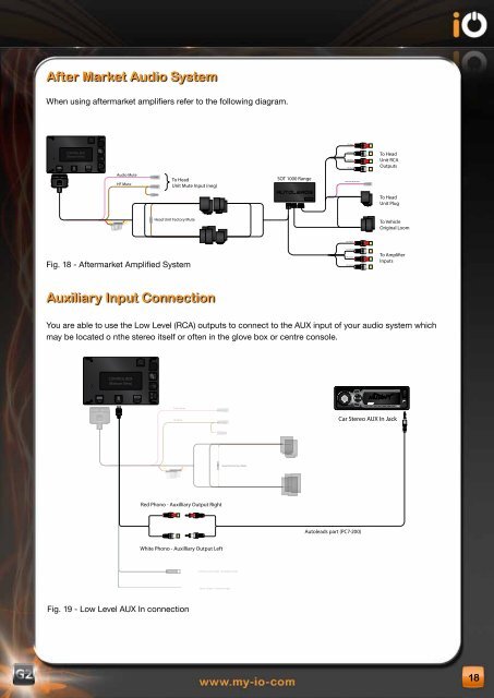
After Market Audio system<br />
When using aftermarket amplifiers refer to the following diagram.<br />
ISO<br />
CONTROL BOX<br />
(Bottom View)<br />
iPod<br />
Audio Mute<br />
HF Mute<br />
To Head<br />
Unit Mute Input (neg)<br />
Head Unit Factory Mute<br />
Fig. 18 - Aftermarket Amplified System<br />
Auxiliary Input Connection<br />
SOT 1000 Range<br />
You are able to use the Low Level (RCA) outputs to connect to the AUX input of your audio system which<br />
may be located o nthe stereo itself or often in the glove box or centre console.<br />
ISO<br />
CONTROL BOX<br />
(Bottom View)<br />
AUX<br />
Audio Mute<br />
HF Mute<br />
Red Phono - Auxilliary Output Right<br />
White Phono - Auxilliary Output Left<br />
Fig. 19 - Low Level AUX In connection<br />
iPod<br />
Head Unit Factory Mute<br />
3.5mm Jack Socket - Auxilliary input<br />
Blue / Green - Reverse Input<br />
AMI-030<br />
FR Input<br />
FL Input<br />
RR Input<br />
RL Input<br />
Head Unit Mute Input<br />
FR Output<br />
FL Output<br />
RR Output<br />
RL Output<br />
Autoleads part (PC7-200)<br />
DISP<br />
TA<br />
AF<br />
BD/ENT<br />
PTY<br />
A/PS<br />
MD/LD<br />
SCAN<br />
To Head<br />
Unit RCA<br />
Outputs<br />
To Head<br />
Unit Plug<br />
To Vehicle<br />
Original Loom<br />
To Ampli�er<br />
Inputs<br />
1 PAU 2 RPT 3 INT 4 RDM 5 6 MUTE<br />
Car Stereo AUX In Jack<br />
AUX IN<br />
18