camlog® prosthetics
camlog® prosthetics
camlog® prosthetics

Create successful ePaper yourself
Turn your PDF publications into a flip-book with our unique Google optimized e-Paper software.
THE CAMLOG ® CAMLOG<br />
IMPLANT SYSTEM<br />
SYSTEM INFORMATION<br />
® IMPLANT SYSTEM<br />
CAMLOG SURFACE STRUCTURES<br />
Promote ® surface<br />
CAMLOG ® SCREW-LINE and ROOT-LINE implants are available<br />
with the Promote ® surface. On CAMLOG ® SCREW-LINE<br />
implants, the abrasive-blasted, acid-etched Promote ® surface<br />
extends up to 1.4 mm under the implant shoulder and the<br />
Promote ® plus surface up to 0.4 mm under the implant shoulder.<br />
On CAMLOG ® ROOT-LINE implants, the surface extends<br />
up to 2.0 mm under the implant shoulder. The Promote ® surface<br />
has proven its worth as a surface for anchoring dental<br />
implants in the bone and has shown good scientific results<br />
in osteohistology and in pull-out trials. These results suggest<br />
that the Promote ® surface leads to rapid osseointegration of<br />
the CAMLOG ® implants.<br />
Promote ® surface<br />
CAMLOG ® Tube-in-Tube Implant-Abutment<br />
Connection<br />
All CAMLOG ® implants are equipped with the proven Tubein-Tube<br />
implant abutment connection and feature three<br />
symmetrically arranged grooves (width 0.5 or 0.7 mm, depth<br />
1.2 mm).<br />
CAMLOG ® SCREW-LINE implants have square grooves (inner<br />
configuration of the K-Series) in the cylindrical implant<br />
neck area.<br />
CAMLOG ® ROOT-LINE implants feature round grooves in<br />
the cylindrical implant neck area.<br />
6<br />
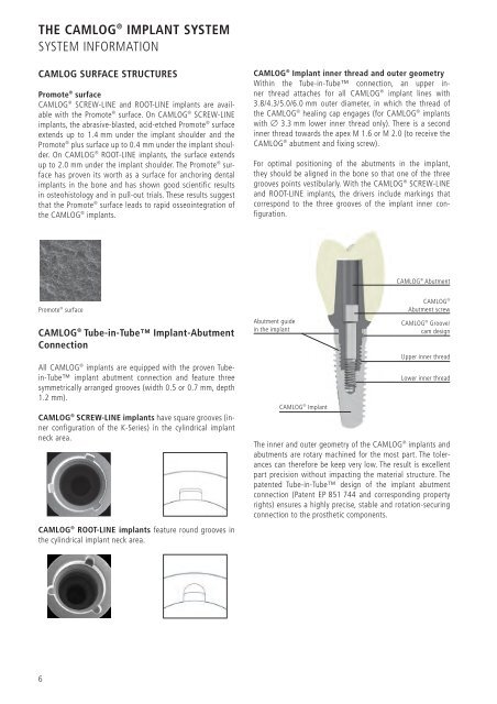
CAMLOG ® Implant inner thread and outer geometry<br />
Within the Tube-in-Tube connection, an upper inner<br />
thread attaches for all CAMLOG ® implant lines with<br />
3.8/4.3/5.0/6.0 mm outer diameter, in which the thread of<br />
the CAMLOG ® healing cap engages (for CAMLOG ® implants<br />
with Ø 3.3 mm lower inner thread only). There is a second<br />
inner thread towards the apex M 1.6 or M 2.0 (to receive the<br />
CAMLOG ® abutment and fixing screw).<br />
For optimal positioning of the abutments in the implant,<br />
they should be aligned in the bone so that one of the three<br />
grooves points vestibularly. With the CAMLOG ® SCREW-LINE<br />
and ROOT-LINE implants, the drivers include markings that<br />
correspond to the three grooves of the implant inner configuration.<br />
Abutment guide<br />
in the implant<br />
CAMLOG ® Implant<br />
CAMLOG ® Abutment<br />
CAMLOG ®<br />
Abutment screw<br />
CAMLOG ® Groove/<br />
cam design<br />
Upper inner thread<br />
Lower inner thread<br />
The inner and outer geometry of the CAMLOG ® implants and<br />
abutments are rotary machined for the most part. The tolerances<br />
can therefore be keep very low. The result is excellent<br />
part precision without impacting the material structure. The<br />
patented Tube-in-Tube design of the implant abutment<br />
connection (Patent EP 851 744 and corresponding property<br />
rights) ensures a highly precise, stable and rotation-securing<br />
connection to the prosthetic components.