Security analysis of Dutch smart metering systems - Multiple Choices
Security analysis of Dutch smart metering systems - Multiple Choices
Security analysis of Dutch smart metering systems - Multiple Choices

Create successful ePaper yourself
Turn your PDF publications into a flip-book with our unique Google optimized e-Paper software.
2.5.2 Optical link<br />
4.1 Port P0 The optical link is accessed using an IEC 62056-21 compatible probe on the front 4 panel PRACTICAL <strong>of</strong> the meter. ANALYSIS<br />
Transmission speed is 1200 bauds and the protocol complies with international standard<br />
IEC 62056-31.<br />
Portable data<br />
terminal<br />
Optical probe<br />
To avoid any untimely modification, an option can be factory-programmed to authorise optical link<br />
programming only when the terminal cover is open.<br />
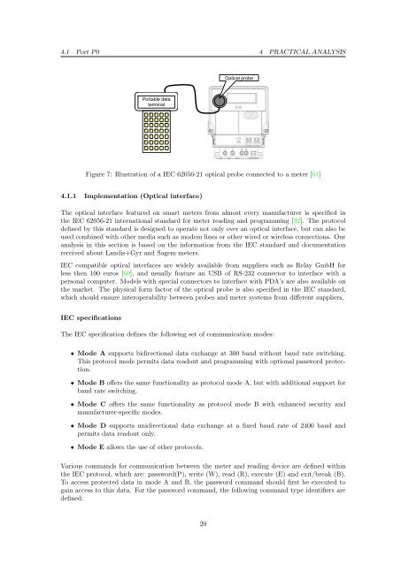
Figure 7: Illustration <strong>of</strong> a IEC 62056-21 optical probe connected to a meter [61]<br />
4.1.1 2.6 Implementation Options (Optical interface)<br />
The optical<br />
2.6.1 Pulse<br />
interface<br />
emitting<br />
featured<br />
device<br />
on <strong>smart</strong> meters from almost every manufacturer is specified in<br />
the IEC 62056-21 international standard for meter reading and programming [32]. The protocol<br />
defined by this Depending standard on the isversion, designed the meter to operate is equipped not with only a pulse over emitting an optical device in interface, accordance but with can also be<br />
used combined standards withDIN other 43864 media and IEC such 62053-31. as modem Its position lines on the or meter other is described wired in orparagraph wireless “Auxiliary connections. Our<br />
terminals”, on page 25. Pulse output value is 1 Wh/imp (imported active energy measurement only).<br />
<strong>analysis</strong> in this section is based on the information from the IEC standard and documentation<br />
received about Landis+Gyr and Sagem meters.<br />
IEC compatible optical interfaces are widely available from suppliers such as Relay GmbH for<br />
less then 100 euros [60], and usually feature an USB <strong>of</strong> RS-232 connector to interface with a<br />
personal computer. Models with special connectors to interface with PDA’s are also available on<br />
the market. The physical form factor <strong>of</strong> the optical probe is also specified in the IEC standard,<br />
which should ensure interoperability between probes and meter <strong>systems</strong> from different suppliers.<br />
IEC specifications<br />
The IEC specification defines the following set <strong>of</strong> communication modes:<br />
• Mode A supports bidirectional data exchange at 300 baud without baud rate switching.<br />
This protocol mode permits data readout Page 16 and programming with optional password protection.<br />
This document is the property <strong>of</strong> SAGEM. It may not be copied or communicated without written consent. This document has no contractual value.<br />
• Mode B <strong>of</strong>fers the same functionality as protocol mode A, but with additional support for<br />
baud rate switching.<br />
• Mode C <strong>of</strong>fers the same functionality as protocol mode B with enhanced security and<br />
manufacturer-specific modes.<br />
• Mode D supports unidirectional data exchange at a fixed baud rate <strong>of</strong> 2400 baud and<br />
permits data readout only.<br />
• Mode E allows the use <strong>of</strong> other protocols.<br />
Various commands for communication between the meter and reading device are defined within<br />
the IEC protocol, which are: password(P), write (W), read (R), execute (E) and exit/break (B).<br />
To access protected data in mode A and B, the password command should first be executed to<br />
gain access to this data. For the password command, the following command type identifiers are<br />
defined:<br />
20