Security analysis of Dutch smart metering systems - Multiple Choices
Security analysis of Dutch smart metering systems - Multiple Choices
Security analysis of Dutch smart metering systems - Multiple Choices

You also want an ePaper? Increase the reach of your titles
YUMPU automatically turns print PDFs into web optimized ePapers that Google loves.
4.4 Port P3 4 PRACTICAL ANALYSIS<br />
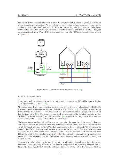
The <strong>smart</strong> meter communicates with a Data Concentrator (DC) which is typically located at<br />
a local transformer substation. At the substation the medium voltage network is connected to<br />
the low voltage “consumer” network. A DC is responsible for collecting the data <strong>of</strong> the <strong>smart</strong><br />
meters in the connected low voltage network. The data is communicated from the DC to the grid<br />
operators network using IP or GPRS. A schematic overview <strong>of</strong> a PLC implementation can be seen<br />
in figure 17.<br />
Medium<br />
Voltage<br />
DC<br />
Substation<br />
Meter to data concentrator<br />
CAS<br />
GPRS<br />
Internet<br />
Low<br />
Voltage<br />
E G W<br />
Electricity<br />
Gas<br />
Water<br />
Figure 17: PLC <strong>smart</strong> <strong>metering</strong> implementation [22]<br />
E G W<br />
In this paragraph the communication between the <strong>smart</strong> meter and the DC will be discussed using<br />
the 7 layers <strong>of</strong> the OSI model [37].<br />
All devices using PLC communication must conform to the frequency allocation in CENELEC,<br />
Frequency Band Allocation for Europe, defined in EN 50065-1 [14]. The IEC 61334-5 series<br />
defines reliable mechanisms for transmission <strong>of</strong> data on a medium or low voltage transmission or<br />
distribution system [21]. The <strong>smart</strong> meters which we encountered in the pilot projects use the<br />
CENELEC A-Band (9-95kHz) and IEC 61334-5-1 [31] standard for the physical layer and the<br />
media access control (MAC) section <strong>of</strong> the data link layer.<br />
PLC uses a shared medium, all residences are connected to the same electricity network. Because<br />
PLC signals weaken in strength when the distances increases, <strong>smart</strong> meters in residences can<br />
repeat the signal from and to the DC so that larger areas up to approximately 700 meters can be<br />
covered. The DC determines which meters will function as a repeater. Seven <strong>of</strong> these repeaters<br />
can be setup in a chain which should enable the DC to reach even the most distant and most<br />
difficult to reach meters, as shown in figure 18 for the Sagem implementation. In practice this<br />
means that <strong>smart</strong> meters receive data from other meters enabling somebody to sniff <strong>metering</strong> data<br />
<strong>of</strong> these meters.<br />
Consumers are allowed to plug-in any device into the electricity network they like. One <strong>of</strong> the<br />
downsides <strong>of</strong> the electricity network is that devices plugged into the electricity network can influence<br />
the PLC signals that pass the network. From our contact at Delta we heard that an<br />
34