

NXP 80C552, 83/87C552, P80C562, P83C562 Family Overview - Keil
NXP 80C552, 83/87C552, P80C562, P83C562 Family Overview - Keil
NXP 80C552, 83/87C552, P80C562, P83C562 Family Overview - Keil

You also want an ePaper? Increase the reach of your titles
YUMPU automatically turns print PDFs into web optimized ePapers that Google loves.
Philips Semiconductors<br />
80C51 <strong>Family</strong> Derivatives 8XC552/562 overview<br />
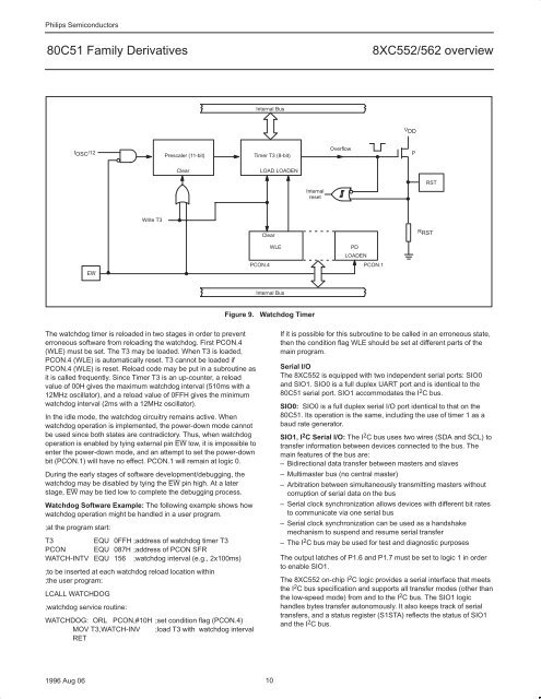
f OSC /12<br />
EW<br />
Write T3<br />
Prescaler (11-bit)<br />
Clear<br />
The watchdog timer is reloaded in two stages in order to prevent<br />
erroneous software from reloading the watchdog. First PCON.4<br />
(WLE) must be set. The T3 may be loaded. When T3 is loaded,<br />
PCON.4 (WLE) is automatically reset. T3 cannot be loaded if<br />
PCON.4 (WLE) is reset. Reload code may be put in a subroutine as<br />
it is called frequently. Since Timer T3 is an up-counter, a reload<br />
value of 00H gives the maximum watchdog interval (510ms with a<br />
12MHz oscillator), and a reload value of 0FFH gives the minimum<br />
watchdog interval (2ms with a 12MHz oscillator).<br />
In the idle mode, the watchdog circuitry remains active. When<br />
watchdog operation is implemented, the power-down mode cannot<br />
be used since both states are contradictory. Thus, when watchdog<br />
operation is enabled by tying external pin EW low, it is impossible to<br />
enter the power-down mode, and an attempt to set the power-down<br />
bit (PCON.1) will have no effect. PCON.1 will remain at logic 0.<br />
During the early stages of software development/debugging, the<br />
watchdog may be disabled by tying the EW pin high. At a later<br />
stage, EW may be tied low to complete the debugging process.<br />
Watchdog Software Example: The following example shows how<br />
watchdog operation might be handled in a user program.<br />
;at the program start:<br />
T3 EQU 0FFH ;address of watchdog timer T3<br />
PCON EQU 087H ;address of PCON SFR<br />
WATCH-INTV EQU 156 ;watchdog interval (e.g., 2x100ms)<br />
;to be inserted at each watchdog reload location within<br />
;the user program:<br />
LCALL WATCHDOG<br />
;watchdog service routine:<br />
WATCHDOG: ORL PCON,#10H ;set condition flag (PCON.4)<br />
MOV T3,WATCH-INV ;load T3 with watchdog interval<br />
RET<br />
Internal Bus<br />
Timer T3 (8-bit)<br />
1996 Aug 06 10<br />
LOAD LOADEN<br />
Clear<br />
WLE<br />
Internal Bus<br />
Internal<br />
reset<br />
Overflow<br />
PD<br />
LOADEN<br />
PCON.4 PCON.1<br />
Figure 9. Watchdog Timer<br />
V DD<br />
P<br />
RST<br />
R RST<br />
If it is possible for this subroutine to be called in an erroneous state,<br />
then the condition flag WLE should be set at different parts of the<br />
main program.<br />
Serial I/O<br />
The 8XC552 is equipped with two independent serial ports: SIO0<br />
and SIO1. SIO0 is a full duplex UART port and is identical to the<br />
80C51 serial port. SIO1 accommodates the I2C bus.<br />
SIO0: SIO0 is a full duplex serial I/O port identical to that on the<br />
80C51. Its operation is the same, including the use of timer 1 as a<br />
baud rate generator.<br />
SIO1, I2C Serial I/O: The I2C bus uses two wires (SDA and SCL) to<br />
transfer information between devices connected to the bus. The<br />
main features of the bus are:<br />
– Bidirectional data transfer between masters and slaves<br />
– Multimaster bus (no central master)<br />
– Arbitration between simultaneously transmitting masters without<br />
corruption of serial data on the bus<br />
– Serial clock synchronization allows devices with different bit rates<br />
to communicate via one serial bus<br />
– Serial clock synchronization can be used as a handshake<br />
mechanism to suspend and resume serial transfer<br />
– The I2C bus may be used for test and diagnostic purposes<br />
The output latches of P1.6 and P1.7 must be set to logic 1 in order<br />
to enable SIO1.<br />
The 8XC552 on-chip I 2 C logic provides a serial interface that meets<br />
the I 2 C bus specification and supports all transfer modes (other than<br />
the low-speed mode) from and to the I 2 C bus. The SIO1 logic<br />
handles bytes transfer autonomously. It also keeps track of serial<br />
transfers, and a status register (S1STA) reflects the status of SIO1<br />
and the I 2 C bus.


