

NXP 80C552, 83/87C552, P80C562, P83C562 Family Overview - Keil
NXP 80C552, 83/87C552, P80C562, P83C562 Family Overview - Keil
NXP 80C552, 83/87C552, P80C562, P83C562 Family Overview - Keil

Create successful ePaper yourself
Turn your PDF publications into a flip-book with our unique Google optimized e-Paper software.
Philips Semiconductors<br />
80C51 <strong>Family</strong> Derivatives 8XC552/562 overview<br />
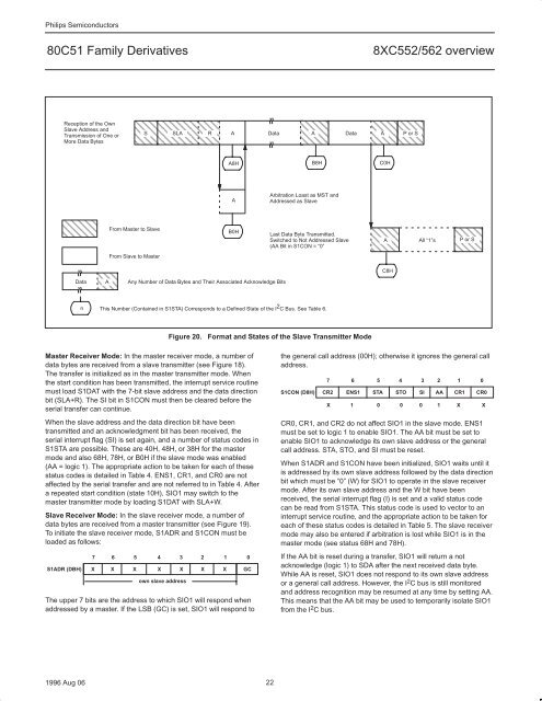
Reception of the Own<br />
Slave Address and<br />
Transmission of One or<br />
More Data Bytes<br />
ÇÇÇÇ<br />
ÇÇÇÇ<br />
ÇÇÇÇ<br />
Data A<br />
ÇÇÇÇ<br />
ÇÇ<br />
ÇÇ<br />
n<br />
S SLA R A Data A<br />
Data A P or S<br />
ÇÇÇÇÇÇÇÇ<br />
ÇÇÇÇÇÇÇÇ<br />
ÇÇÇÇÇÇÇÇ<br />
From Master to Slave<br />
From Slave to Master<br />
1996 Aug 06 22<br />
A8H<br />
B0H<br />
Any Number of Data Bytes and Their Associated Acknowledge Bits<br />
This Number (Contained in S1STA) Corresponds to a Defined State of the I 2 C Bus. See Table 6.<br />
Master Receiver Mode: In the master receiver mode, a number of<br />
data bytes are received from a slave transmitter (see Figure 18).<br />
The transfer is initialized as in the master transmitter mode. When<br />
the start condition has been transmitted, the interrupt service routine<br />
must load S1DAT with the 7-bit slave address and the data direction<br />
bit (SLA+R). The SI bit in S1CON must then be cleared before the<br />
serial transfer can continue.<br />
When the slave address and the data direction bit have been<br />
transmitted and an acknowledgment bit has been received, the<br />
serial interrupt flag (SI) is set again, and a number of status codes in<br />
S1STA are possible. These are 40H, 48H, or 38H for the master<br />
mode and also 68H, 78H, or B0H if the slave mode was enabled<br />
(AA = logic 1). The appropriate action to be taken for each of these<br />
status codes is detailed in Table 4. ENS1, CR1, and CR0 are not<br />
affected by the serial transfer and are not referred to in Table 4. After<br />
a repeated start condition (state 10H), SIO1 may switch to the<br />
master transmitter mode by loading S1DAT with SLA+W.<br />
Slave Receiver Mode: In the slave receiver mode, a number of<br />
data bytes are received from a master transmitter (see Figure 19).<br />
To initiate the slave receiver mode, S1ADR and S1CON must be<br />
loaded as follows:<br />
A<br />
ÇÇÇ<br />
ÇÇÇÇ ÇÇÇ<br />
ÇÇÇ<br />
ÇÇÇÇ<br />
ÇÇÇ ÇÇÇ ÇÇÇ<br />
C0H<br />
ÇÇÇ<br />
ÇÇÇÇ<br />
ÇÇÇ ÇÇÇ<br />
B8H<br />
Arbitration Loast as MST and<br />
Addressed as Slave<br />
Last Data Byte Transmitted.<br />
Switched to Not Addressed Slave<br />
(AA Bit in S1CON = “0”<br />
Figure 20. Format and States of the Slave Transmitter Mode<br />
7 6 5 4 3 2 1 0<br />
S1ADR (DBH) X X X X X X X GC<br />
own slave address<br />
The upper 7 bits are the address to which SIO1 will respond when<br />
addressed by a master. If the LSB (GC) is set, SIO1 will respond to<br />
ÇÇÇ<br />
A<br />
ÇÇÇ<br />
ÇÇÇ<br />
C8H<br />
All “1”s<br />
ÇÇÇ<br />
P or S<br />
ÇÇÇ<br />
ÇÇÇ<br />
the general call address (00H); otherwise it ignores the general call<br />
address.<br />
7 6 5 4 3 2 1 0<br />
S1CON (D8H) CR2 ENS1 STA STO SI AA CR1 CR0<br />
X 1 0 0 0 1 X X<br />
CR0, CR1, and CR2 do not affect SIO1 in the slave mode. ENS1<br />
must be set to logic 1 to enable SIO1. The AA bit must be set to<br />
enable SIO1 to acknowledge its own slave address or the general<br />
call address. STA, STO, and SI must be reset.<br />
When S1ADR and S1CON have been initialized, SIO1 waits until it<br />
is addressed by its own slave address followed by the data direction<br />
bit which must be “0” (W) for SIO1 to operate in the slave receiver<br />
mode. After its own slave address and the W bit have been<br />
received, the serial interrupt flag (I) is set and a valid status code<br />
can be read from S1STA. This status code is used to vector to an<br />
interrupt service routine, and the appropriate action to be taken for<br />
each of these status codes is detailed in Table 5. The slave receiver<br />
mode may also be entered if arbitration is lost while SIO1 is in the<br />
master mode (see status 68H and 78H).<br />
If the AA bit is reset during a transfer, SIO1 will return a not<br />
acknowledge (logic 1) to SDA after the next received data byte.<br />
While AA is reset, SIO1 does not respond to its own slave address<br />
or a general call address. However, the I 2 C bus is still monitored<br />
and address recognition may be resumed at any time by setting AA.<br />
This means that the AA bit may be used to temporarily isolate SIO1<br />
from the I 2 C bus.


