NXP 80C552, 83/87C552, P80C562, P83C562 Family Overview - Keil
NXP 80C552, 83/87C552, P80C562, P83C562 Family Overview - Keil
NXP 80C552, 83/87C552, P80C562, P83C562 Family Overview - Keil
Create successful ePaper yourself
Turn your PDF publications into a flip-book with our unique Google optimized e-Paper software.
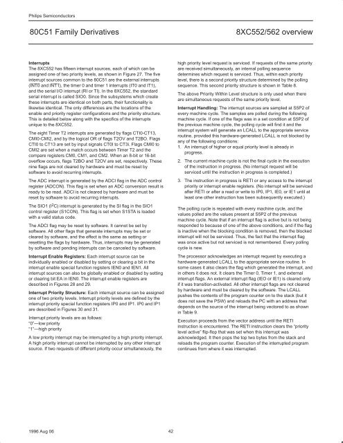
Philips Semiconductors<br />
80C51 <strong>Family</strong> Derivatives 8XC552/562 overview<br />
Interrupts<br />
The 8XC552 has fifteen interrupt sources, each of which can be<br />
assigned one of two priority levels, as shown in Figure 27. The five<br />
interrupt sources common to the 80C51 are the external interrupts<br />
(INT0 and INT1), the timer 0 and timer 1 interrupts (IT0 and IT1),<br />
and the serial I/O interrupt (RI or TI). In the 8XC552, the standard<br />
serial interrupt is called SIO0. Since the subsystems which create<br />
these interrupts are identical on both parts, their functionality is<br />
likewise identical. The only differences are the locations of the<br />
enable and priority register configurations and the priority structure.<br />
This is detailed below along with the specifics of the interrupts<br />
unique to the 8XC552.<br />
The eight Timer T2 interrupts are generated by flags CTI0-CT13,<br />
CMI0-CMI2, and by the logical OR of flags T2OV and T2BO. Flags<br />
CTI0 to CT13 are set by input signals CT0I to CT3i. Flags CMI0 to<br />
CMI2 are set when a match occurs between Timer T2 and the<br />
compare registers CM0, CM1, and CM2. When an 8-bit or 16-bit<br />
overflow occurs, flags T2BO and T2OV are set, respectively. These<br />
nine flags are not cleared by hardware and must be reset by<br />
software to avoid recurring interrupts.<br />
The ADC interrupt is generated by the ADCI flag in the ADC control<br />
register (ADCON). This flag is set when an ADC conversion result is<br />
ready to be read. ADCI is not cleared by hardware and must be<br />
reset by software to avoid recurring interrupts.<br />
The SIO1 (I2C) interrupt is generated by the SI flag in the SIO1<br />
control register (S1CON). This flag is set when S1STA is loaded<br />
with a valid status code.<br />
The ADCI flag may be reset by software. It cannot be set by<br />
software. All other flags that generate interrupts may be set or<br />
cleared by software, and the effect is the same as setting or<br />
resetting the flags by hardware. Thus, interrupts may be generated<br />
by software and pending interrupts can be canceled by software.<br />
Interrupt Enable Registers: Each interrupt source can be<br />
individually enabled or disabled by setting or clearing a bit in the<br />
interrupt enable special function registers IEN0 and IEN1. All<br />
interrupt sources can also be globally enabled or disabled by setting<br />
or clearing bit EA in IEN0. The interrupt enable registers are<br />
described in Figures 28 and 29.<br />
Interrupt Priority Structure: Each interrupt source can be assigned<br />
one of two priority levels. Interrupt priority levels are defined by the<br />
interrupt priority special function registers IP0 and IP1. IP0 and IP1<br />
are described in Figures 30 and 31.<br />
Interrupt priority levels are as follows:<br />
“0”—low priority<br />
“1”—high priority<br />
A low priority interrupt may be interrupted by a high priority interrupt.<br />
A high priority interrupt cannot be interrupted by any other interrupt<br />
source. If two requests of different priority occur simultaneously, the<br />
1996 Aug 06 42<br />
high priority level request is serviced. If requests of the same priority<br />
are received simultaneously, an internal polling sequence<br />
determines which request is serviced. Thus, within each priority<br />
level, there is a second priority structure determined by the polling<br />
sequence. This second priority structure is shown in Table 8.<br />
The above Priority Within Level structure is only used when there<br />
are simultaneous requests of the same priority level.<br />
Interrupt Handling: The interrupt sources are sampled at S5P2 of<br />
every machine cycle. The samples are polled during the following<br />
machine cycle. If one of the flags was in a set condition at S5P2 of<br />
the previous machine cycle, the polling cycle will find it and the<br />
interrupt system will generate an LCALL to the appropriate service<br />
routine, provided this hardware-generated LCALL is not blocked by<br />
any of the following conditions:<br />
1. An interrupt of higher or equal priority level is already in<br />
progress.<br />
2. The current machine cycle is not the final cycle in the execution<br />
of the instruction in progress. (No interrupt request will be<br />
serviced until the instruction in progress is completed.)<br />
3. The instruction in progress is RETI or any access to the interrupt<br />
priority or interrupt enable registers. (No interrupt will be serviced<br />
after RETI or after a read or write to IP0, IP1, IE0, or IE1 until at<br />
least one other instruction has been subsequently executed.)<br />
The polling cycle is repeated with every machine cycle, and the<br />
values polled are the values present at S5P2 of the previous<br />
machine cycle. Note that if an interrupt flag is active but is not being<br />
responded to because of one of the above conditions, and if the flag<br />
is inactive when the blocking condition is removed, then the blocked<br />
interrupt will not be serviced. Thus, the fact that the interrupt flag<br />
was once active but not serviced is not remembered. Every polling<br />
cycle is new.<br />
The processor acknowledges an interrupt request by executing a<br />
hardware-generated LCALL to the appropriate service routine. In<br />
some cases it also clears the flag which generated the interrupt, and<br />
in others it does not. It clears the Timer 0, Timer 1, and external<br />
interrupt flags. An external interrupt flag (IEO or IE1) is cleared only<br />
if it was transition-activated. All other interrupt flags are not cleared<br />
by hardware and must be cleared by the software. The LCALL<br />
pushes the contents of the program counter on to the stack (but it<br />
does not save the PSW) and reloads the PC with an address that<br />
depends on the source of the interrupt being vectored to as shown<br />
in Table 9.<br />
Execution proceeds from the vector address until the RETI<br />
instruction is encountered. The RETI instruction clears the “priority<br />
level active” flip-flop that was set when this interrupt was<br />
acknowledged. It then pops the top two bytes from the stack and<br />
reloads the program counter. Execution of the interrupted program<br />
continues from where it was interrupted.


