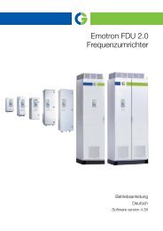
- Page 1: Emotron FDU 2.0 AC drive Instructio
- Page 6 and 7: Condensation If the AC drive is mov
- Page 8 and 9: 9.2.2 Indications on the display...
- Page 10 and 11: Position for 003- 074 10 - Painted
- Page 12 and 13: 1.7 Glossary 1.7.1 Abbreviations an
- Page 14 and 15: 2.2 Stand-alone units The AC drive
- Page 16 and 17: 22.5 240 120 10 30 925 Ø16(3) Cabl
- Page 18 and 19: 2.3.3 Mounting schemes Fig. 15 FDU4
- Page 20 and 21: 18 Mounting CG Drives & Automation,
- Page 22 and 23: PE Fig. 19 Mains and motor connecti
- Page 24 and 25: Connect motor cables 1. Remove the
- Page 26 and 27: PEBB 1 (Master) PEBB 2 PEBB 3 Mains
- Page 28 and 29: 26 Installation CG Drives & Automat
- Page 30 and 31: 4.2 Terminal connections The termin
- Page 32 and 33: 4.5 Connecting the Control Signals
- Page 34 and 35: 4.5.5 Current signals ((0)4-20 mA)
- Page 36 and 37: 5.3 Remote control In this example
- Page 38 and 39: 36 Getting Started CG Drives & Auto
- Page 40 and 41: 6.1.3Compressors 6.1.4Blowers Chall
- Page 42 and 43: Examples Different parameter sets c
- Page 44 and 45: 7.2 Remote control functions Operat
- Page 46 and 47: INPUTS ENABLE STOP RUN R RUN L OUTP
- Page 48 and 49: . Ramp-down phase Stationary phase
- Page 50 and 51: 7.6.2 Fixed MASTER This is the defa
- Page 52 and 53:
7.6.6 PID control When using the Pu
- Page 54 and 55:
7.6.8 Checklist And Tips 1. Main Fu
- Page 56 and 57:
Stopping an additional pump This fi
- Page 58 and 59:
56 EMC and standards CG Drives & Au
- Page 60 and 61:
300 Process StpA Fig. 59 Example 1s
- Page 62 and 63:
Remote mode When the AC drive is sw
- Page 64 and 65:
9.7 Programming example This exampl
- Page 66 and 67:
10.3 Motor data Communication infor
- Page 68 and 69:
Programming example: typedef struct
- Page 70 and 71:
Communication information Modbus In
- Page 72 and 73:
Run/Stop Control [215] This functio
- Page 74 and 75:
Fig. 70 Rotation In this menu you s
- Page 76 and 77:
Motor Frequency [222] Set the nomin
- Page 78 and 79:
Motor Identification Run [229] This
- Page 80 and 81:
Off 0 Random modulation is Off. On
- Page 82 and 83:
Motor I 2 t Current [232] Sets the
- Page 84 and 85:
PT100 Inputs [236] Sets which of PT
- Page 86 and 87:
Communication information Modbus In
- Page 88 and 89:
Default: 0 (no Autoreset) Range: 0-
- Page 90 and 91:
Undervoltage [259] Delay time start
- Page 92 and 93:
Communication Error [25I] Delay tim
- Page 94 and 95:
External Motor Temperature [25R] De
- Page 96 and 97:
Default: 9600 2400 0 4800 1 9600 2
- Page 98 and 99:
Communication information Modbus In
- Page 100 and 101:
Communication information Modbus In
- Page 102 and 103:
Character No. for serial comm. ê 4
- Page 104 and 105:
Communication information Modbus In
- Page 106 and 107:
Acceleration Time to Minimum Speed
- Page 108 and 109:
Spinstart [33A] The spinstart will
- Page 110 and 111:
Release Speed [33D] Mechanical Brak
- Page 112 and 113:
Note! Function is deactivated if se
- Page 114 and 115:
Communication information Modbus In
- Page 116 and 117:
11.3.6 Torques [350] Menu with all
- Page 118 and 119:
11.3.7 Preset References [360] Moto
- Page 120 and 121:
Process reference Process feedback
- Page 122 and 123:
PID Steady State Test [388] In appl
- Page 124 and 125:
Change Condition [394] This paramet
- Page 126 and 127:
Stop Delay [39A] This delay time mu
- Page 128 and 129:
Settle Time Stop [39F] The settle s
- Page 130 and 131:
11.4 Load Monitor and Process Prote
- Page 132 and 133:
Communication information Modbus In
- Page 134 and 135:
Normal Load [41B] Set the level of
- Page 136 and 137:
Overvolt control [424] Used to swit
- Page 138 and 139:
NOTE: For bipol function, input Run
- Page 140 and 141:
Communication information Modbus In
- Page 142 and 143:
Communication information Modbus In
- Page 144 and 145:
Pump1 Feedb Pump2 Feedb Pump3 Feedb
- Page 146 and 147:
Communication information Modbus In
- Page 148 and 149:
Example Set the AnOut function for
- Page 150 and 151:
Max Alarm 20 Max PreAlarm 21 Min Al
- Page 152 and 153:
Relay 3 [553] Sets the function for
- Page 154 and 155:
11.6 Logical Functions and Timers [
- Page 156 and 157:
20 mA 4 mA 3.2 mA 2.4 mA CA1 Mode R
- Page 158 and 159:
Table 28 Comments to Fig. 111 regar
- Page 160 and 161:
Analogue Comparator 2, Level High [
- Page 162 and 163:
Analogue Comparator 3, Polar [6135]
- Page 164 and 165:
Digital Comparator 3 [6153] Functio
- Page 166 and 167:
Y Operator 2 [624] Selects the seco
- Page 168 and 169:
Timer 1 Trig [641] Default: Off Sel
- Page 170 and 171:
Timer 2 Delay [653] Default: 0:00:0
- Page 172 and 173:
Counter 1 Low value [6614] Sets cou
- Page 174 and 175:
11.7 View Operation/Status [700] Me
- Page 176 and 177:
Heatsink Temperature [71A] Displays
- Page 178 and 179:
Digital Input Status [723] Indicate
- Page 180 and 181:
11.7.3 Stored values [730] The show
- Page 182 and 183:
Trip message [811]-[81O] The inform
- Page 184 and 185:
Software [922] Shows the software v
- Page 186 and 187:
Table 31 List of trips and warnings
- Page 188 and 189:
Table 32 Trip condition, their poss
- Page 190 and 191:
Table 32 Trip condition, their poss
- Page 192 and 193:
190 Troubleshooting, Diagnoses and
- Page 194 and 195:
13.4 Brake chopper All AC drive siz
- Page 196 and 197:
13.8 Serial communication and field
- Page 198 and 199:
Fig. 131 Connection of safe stop op
- Page 200 and 201:
198 Options CG Drives & Automation,
- Page 202 and 203:
Table 39 Typical motor power at mai
- Page 204 and 205:
Table 41 Typical motor power at mai
- Page 206 and 207:
14.2 General electrical specificati
- Page 208 and 209:
14.5 Dimensions and Weights The tab
- Page 210 and 211:
14.7 Fuses, cable crosssections and
- Page 212 and 213:
14.7.2 Fuses and cable dimensions a
- Page 214 and 215:
14.8 Control signals Table 53 Termi
- Page 216 and 217:
Factory setting Customer Page 2667
- Page 218 and 219:
Factory setting Customer Page 5363
- Page 220 and 221:
218 Menu List CG Drives & Automatio
- Page 222 and 223:
STOP/RESET ........................
- Page 224:
External Control Panel (ECP) 191 I/