- Page 1: Emotron FDU 2.0 AC drive Instructio
- Page 5 and 6: Safety Instructions Congratulations
- Page 7 and 8: Contents Safety Instructions Conten
- Page 9 and 10: 1. Introduction Emotron FDUis used
- Page 11 and 12: Table 1 Standards European All USA
- Page 13 and 14: 2. Mounting This chapter describes
- Page 15 and 16: 512 Fig. 8 FDU48/52: Model 026 to 0
- Page 17 and 18: 2.3 Cabinet mounting 2.3.1 Cooling
- Page 19 and 20: Fig. 16 2250 2000 2250 2000 2250 20
- Page 21 and 22: 3. Installation The description of
- Page 23 and 24: Switches between the motor and the
- Page 25 and 26: AC drive model 48-300 & 69-210 and
- Page 27 and 28: 3.5.1 Dimension of cables and fuses
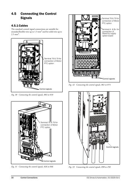
- Page 29 and 30: 4. Control Connections 4.1 Control
- Page 31: 4.4 Connection example Fig. 29 give
- Page 35 and 36: 5. Getting Started This chapter is
- Page 37 and 38: 5.4 Local control Manual control vi
- Page 39 and 40: 6. Applications This chapter contai
- Page 41 and 42: 7. Main Features This chapter conta
- Page 43 and 44: Example The motor is protected by a
- Page 45 and 46: Reset and Autoreset operation If th
- Page 47 and 48: 7.5 Load Monitor and Process Protec
- Page 49 and 50: 7.6 Pump function 7.6.1 Introductio
- Page 51 and 52: 7.6.4 Feedback 'Status' input In th
- Page 53 and 54: 7.6.7 Wiring Alternating Master Fig
- Page 55 and 56: 7.6.9 Functional Examples of Start/
- Page 57 and 58: 8. EMC and standards 8.1 EMC standa
- Page 59 and 60: 9. Operation via the Control Panel
- Page 61 and 62: 9.2.5 The Toggle and Loc/Rem Key Th
- Page 63 and 64: 500 Inputs/Outputs and Virtual Conn
- Page 65 and 66: 10. Serial communication The AC dri
- Page 67 and 68: 10.6 Description of the EInt format
- Page 69 and 70: 11. Functional Description This cha
- Page 71 and 72: Select Motor [212] This menu is use
- Page 73 and 74: Local/Remote key function [217] The
- Page 75 and 76: Brake chopper activation level is a
- Page 77 and 78: Communication information Modbus In
- Page 79 and 80: Encoder Pulses [22C] Only visible i
- Page 81 and 82: Communication information 11.2.5 Mo
- Page 83 and 84:
Fig. 72 shows how the function inte
- Page 85 and 86:
11.2.6 Parameter Set Handling [240]
- Page 87 and 88:
Load Settings from Control Panel [2
- Page 89 and 90:
Overvolt [255] Delay time starts co
- Page 91 and 92:
Communication information Modbus In
- Page 93 and 94:
Max Alarm [25M] Delay time starts c
- Page 95 and 96:
Encoder [25W] Encoder delay time, s
- Page 97 and 98:
Read/Write [2633] Select read/write
- Page 99 and 100:
Fieldbus Signals [266] Defines modb
- Page 101 and 102:
Process Unit [322] Default: rpm Off
- Page 103 and 104:
Ratio [326] This menu is not visibl
- Page 105 and 106:
pm (NG_06-F11) Nom. Speed Acc Time
- Page 107 and 108:
Acceleration Ramp Type [337] Sets t
- Page 109 and 110:
11.3.4 Mechanical brake control The
- Page 111 and 112:
Wait Before Brake Time [33F] The br
- Page 113 and 114:
11.3.5 Speed [340] Menu with all pa
- Page 115 and 116:
Skip Speed 2 Low [346] The same fun
- Page 117 and 118:
NOTE: A too high level of IxR Compe
- Page 119 and 120:
Table 23 Preset Ctrl3 Preset Ctrl2
- Page 121 and 122:
PID Activation Margin [387] The PID
- Page 123 and 124:
11.3.9 Pump/Fan Control [390] The P
- Page 125 and 126:
Upper Band [397] If the speed of th
- Page 127 and 128:
Settle Time Start [39D] The settle
- Page 129 and 130:
Run Times 1-6 [39H] to [39M] Unit:
- Page 131 and 132:
Alarm Start Delay [414] This parame
- Page 133 and 134:
Min Pre Alarm Response delay [4182]
- Page 135 and 136:
11.4.2 Process Protection [420] Sub
- Page 137 and 138:
[514] AnIn2 Function = Process Ref.
- Page 139 and 140:
Communication information Modbus In
- Page 141 and 142:
AnIn1 Filter [5139] If the input si
- Page 143 and 144:
AnIn4 Set-up [51B] Same functions a
- Page 145 and 146:
Additional digital inputs [529] to
- Page 147 and 148:
AnOut1 Max [5332] This parameter is
- Page 149 and 150:
AnOut2 Setup [535] Preset scaling a
- Page 151 and 152:
!D3 96 Digital comparator 3 inverte
- Page 153 and 154:
11.5.6 Virtual Connections [560] Fu
- Page 155 and 156:
The output signal can be programmed
- Page 157 and 158:
Example This example describes, bot
- Page 159 and 160:
Analogue Comparator 1, Polarity[611
- Page 161 and 162:
CA3 Setup [613] Analogue comparator
- Page 163 and 164:
Analogue Comparator 4, Type [6144]
- Page 165 and 166:
Menu [620] now holds the expression
- Page 167 and 168:
Z Comp 2 [633] Selects the second c
- Page 169 and 170:
Communication information Modbus In
- Page 171 and 172:
11.6.6 Counters [660] Counter funct
- Page 173 and 174:
Counter 2 High value [6623] Functio
- Page 175 and 176:
Communication information Modbus In
- Page 177 and 178:
Description of communication format
- Page 179 and 180:
Communication information Modbus In
- Page 181 and 182:
Reset Energy [7331] Resets the ener
- Page 183 and 184:
Communication information 11.9 Syst
- Page 185 and 186:
12. Troubleshooting, Diagnoses and
- Page 187 and 188:
12.2.1 Technically qualified person
- Page 189 and 190:
Table 32 Trip condition, their poss
- Page 191 and 192:
12.3 Maintenance The AC drive is de
- Page 193 and 194:
13. Options The standard options av
- Page 195 and 196:
Table 35 Brake resistor FDU52 V typ
- Page 197 and 198:
13.10 Safe Stop option To realize a
- Page 199 and 200:
13.11 Output chokes Output chokes,
- Page 201 and 202:
14. Technical Data 14.1 Electrical
- Page 203 and 204:
Table 40 Typical motor power at mai
- Page 205 and 206:
Table 42 Typical motor power at mai
- Page 207 and 208:
14.3 Operation at higher temperatur
- Page 209 and 210:
14.6 Environmental conditions Table
- Page 211 and 212:
Table 50 Fuses, cable cross-section
- Page 213 and 214:
Table 52 Type cables cross-sections
- Page 215 and 216:
15. Menu List On our home page in t
- Page 217 and 218:
Factory setting Customer Page 4161
- Page 219 and 220:
Factory setting Customer Page 6619
- Page 221 and 222:
Index A Abbreviations .............
- Page 223 and 224:
(39H-39M) .........................
- Page 226:
CG Drives & Automation Sweden AB M