D-BAUG - Departement Bau, Umwelt und Geomatik - ETH Zürich
D-BAUG - Departement Bau, Umwelt und Geomatik - ETH Zürich
D-BAUG - Departement Bau, Umwelt und Geomatik - ETH Zürich

Create successful ePaper yourself
Turn your PDF publications into a flip-book with our unique Google optimized e-Paper software.
Highlights ▪ High-Tech Measuring Systems<br />
GPS as Rotational Sensor<br />
Can GPS be used to estimate the orientation<br />
and rotational velocity of the antenna?<br />
by S. Häberling, A. Geiger / IGP<br />
To this day, the satellite-based navigation systems such as the<br />
Global Postioning System (GPS) are mainly used for positioning<br />
applications. An additional method to retrieve 3D rotation anglesfrommeasurementswithasingleGPSantennainreal-time<br />
was demonstrated by a master thesis.This information about<br />
the angular velocities and the full 3D rotation in addition to the<br />
position would enlarge the applicability of GPS in machine control<br />
and air navigation.<br />
The method is using the properties of the circularly polarized<br />
electromagnetic waves that are transmitted by the GPS satellites.<br />
The rotation of the receiver antenna relative to the satellite<br />
antenna generates a phase shift called “phase wind-up”<br />
(Fig.1).Depending on the type of rotation and on the elevation<br />
angleof theincomingsignal thisphaseshift,measuredfromdifferentsatellites,allows<br />
thedescriptionof thefull3Dantennarotation.<br />
For the detection of small phase shifts in GPS raw data it is necessary<br />
to build a linear combination between signals with different<br />
frequencies to eliminate error sources. After a statistical<br />
signal processing with appropriate filtering the results indicate<br />
that minimalrotationalvelocitiesof3–3.5°/saresignificantlydetected<br />
depending on time of day (e.g.ionosphere) and satellite<br />
constellation.Thealgorithmdevelopedfor thedeterminationof<br />
the full 3D rotation generates stable solutions.This was verified<br />
by simulations and real measurements (Fig.2).<br />
74 ▪ D-<strong>BAUG</strong> Annual Report 2009<br />
Fig. 1: A simplified schematic illustration of an incoming circularly<br />
polarized electromagnetic wave. Due to the rotation of the<br />
GPS antenna (blue to red) an angle (phase shift Δφ) occurs between<br />
the two dipole vectors (dashed). They can be described as<br />
a projection from the polarization plane (grey) onto the antenna<br />
plane.<br />
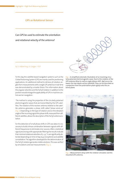
Fig. 2: Measurement setup with the rotation simulator and the<br />
mounted GPS antenna.