DS 7-7R 17-12R Semiconductor Fabrication Facilities ... - FM Global
DS 7-7R 17-12R Semiconductor Fabrication Facilities ... - FM Global
DS 7-7R 17-12R Semiconductor Fabrication Facilities ... - FM Global

You also want an ePaper? Increase the reach of your titles
YUMPU automatically turns print PDFs into web optimized ePapers that Google loves.
REFERENCE DOCUMENT<br />
<strong>FM</strong> <strong>Global</strong> 7-<strong>7R</strong><br />
Property Loss Prevention Data Sheets <strong>17</strong>-<strong>12R</strong><br />
SEMICONDUCTOR FABRICATION FACILITIES<br />
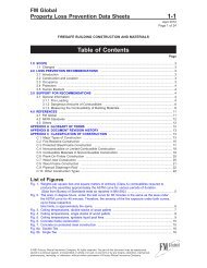
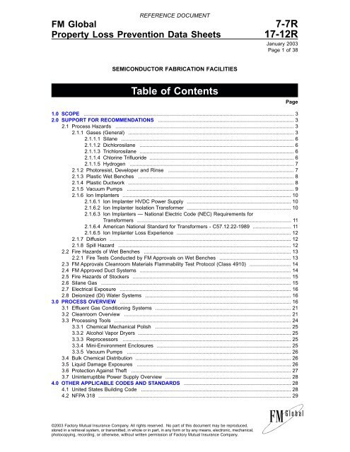
Table of Contents<br />
January 2003<br />
Page1of38<br />
1.0 SCOPE ................................................................................................................................................... 3<br />
2.0 SUPPORT FOR RECOMMENDATIONS ............................................................................................... 3<br />
2.1 Process Hazards ............................................................................................................................. 3<br />
2.1.1 Gases (General) .................................................................................................................... 3<br />
2.1.1.1 Silane ......................................................................................................................... 6<br />
2.1.1.2 Dichlorosilane ............................................................................................................ 6<br />
2.1.1.3 Trichlorosilane ............................................................................................................ 6<br />
2.1.1.4 Chlorine Trifluoride ..................................................................................................... 6<br />
2.1.1.5 Hydrogen ................................................................................................................... 7<br />
2.1.2 Photoresist, Developer and Rinse ........................................................................................ 7<br />
2.1.3 Plastic Wet Benches ............................................................................................................. 8<br />
2.1.4 Plastic Ductwork .................................................................................................................... 8<br />
2.1.5 Vacuum Pumps ..................................................................................................................... 9<br />
2.1.6 Ion Implanters ...................................................................................................................... 10<br />
2.1.6.1 Ion Implanter HVDC Power Supply ......................................................................... 10<br />
2.1.6.2 Ion Implanter Isolation Transformer ......................................................................... 10<br />
2.1.6.3 Ion Implanters — National Electric Code (NEC) Requirements for<br />
Transformers ............................................................................................................ 11<br />
2.1.6.4 American National Standard for Transformers - C57.12.22-1989 ........................... 11<br />
2.1.6.5 Ion Implanter Loss Experience ................................................................................ 12<br />
2.1.7 Diffusion ............................................................................................................................... 12<br />
2.1.8 Spill Hazard ......................................................................................................................... 12<br />
2.2 Fire Hazards of Wet Benches ....................................................................................................... 13<br />
2.2.1 Fire Tests Conducted by <strong>FM</strong> Approvals on Wet Benches .................................................. 13<br />
2.3 <strong>FM</strong> Approvals Cleanroom Materials Flammability Test Protocol (Class 4910) ............................. 14<br />
2.4 <strong>FM</strong> Approved Duct Systems .......................................................................................................... 14<br />
2.5 Fire Hazards of Stockers ............................................................................................................... 15<br />
2.6 Silane Gas ..................................................................................................................................... 15<br />
2.7 Electrical Exposure ........................................................................................................................ 16<br />
2.8 Deionized (DI) Water Systems ...................................................................................................... 16<br />
3.0 PROCESS OVERVIEW ........................................................................................................................ 16<br />
3.1 Effluent Gas Conditioning Systems ............................................................................................... 21<br />
3.2 Cleanroom Overview ..................................................................................................................... 21<br />
3.3 Processing Tools ............................................................................................................................ 24<br />
3.3.1 Chemical Mechanical Polish ............................................................................................... 25<br />
3.3.2 Alcohol Vapor Dryers ........................................................................................................... 25<br />
3.3.3 Reprocessors ...................................................................................................................... 25<br />
3.3.4 Mini-Environment Enclosures .............................................................................................. 25<br />
3.3.5 Vacuum Pumps ................................................................................................................... 26<br />
3.4 Bulk Chemical Distribution ............................................................................................................. 26<br />
3.5 Liquid Damage Exposures ............................................................................................................ 26<br />
3.6 Protection Against Theft ................................................................................................................ 27<br />
3.7 Uninterruptible Power Supply Overview ........................................................................................ 28<br />
4.0 OTHER APPLICABLE CODES AND STANDAR<strong>DS</strong> ........................................................................... 28<br />
4.1 United States Building Code ......................................................................................................... 28<br />
4.2 NFPA 318 ....................................................................................................................................... 29<br />
©2003 Factory Mutual Insurance Company. All rights reserved. No part of this document may be reproduced,<br />
stored in a retrieval system, or transmitted, in whole or in part, in any form or by any means, electronic, mechanical,<br />
photocopying, recording, or otherwise, without written permission of Factory Mutual Insurance Company.<br />
Page
7-<strong>7R</strong><br />
REFERENCE DOCUMENT<br />
<strong>17</strong>-<strong>12R</strong> SEMICONDUCTOR FABRICATION FACILITIES<br />
Page 2<br />
4.3 SEMI S-2 ....................................................................................................................................... 29<br />
4.4 International Codes ........................................................................................................................ 30<br />
4.5 ISO International Cleanroom Standards ........................................................................................ 31<br />
4.5.1 ISO 14644-1 Air Cleanliness Classification .......................................................................... 32<br />
5.0 SEMICONDUCTOR TERMINOLOGY .................................................................................................. 33<br />
6.0 BIBLIOGRAPHY ................................................................................................................................... 38<br />
List of Figures<br />
Fig. 1. Process gas distribution arrangements ............................................................................................. 4<br />
Fig. 2. Wet bench free burn test. ................................................................................................................. 13<br />
Fig. 3. Flow diagram of semiconductor fabrication. ..................................................................................... <strong>17</strong><br />
Fig. 4. <strong>Semiconductor</strong> fabrication facility systems diagram. ........................................................................ 18<br />
Fig. 5. Clean bay service aisle. .................................................................................................................... 22<br />
Fig. 6. Tool service corridor. ......................................................................................................................... 23<br />
Fig. 7. Various arrangements of a wet bench and associated fume exhaust ductwork. ............................ 24<br />
List of Tables<br />
Table 1. Gases Used in <strong>Fabrication</strong> ............................................................................................................. 5<br />
Table 2. Silane Mixtures ................................................................................................................................. 6<br />
Table 3. Flammable and Combustible Liquids Used in <strong>Fabrication</strong> .............................................................. 8<br />
Table 4. Process Reactions ........................................................................................................................... 9<br />
Table 5. Vacuum Applications Used in <strong>Fabrication</strong> ...................................................................................... 10<br />
Table 6. Material Nomenclature and Use .................................................................................................... 14<br />
Table 7. Common Nonflammable <strong>Semiconductor</strong> Process Liquids ........................................................... 26<br />
Table 8. Possible Water Damage Sources ................................................................................................. 27<br />
Table 9. Selected airborne particulate cleanroom classes for cleanrooms and cleanzones<br />
defined by ISO 14644-1 ................................................................................................................. 32<br />
Table 10. Comparison between different Cleanroom Class Standards ....................................................... 32<br />
©2003 Factory Mutual Insurance Company. All rights reserved.
1.0 SCOPE<br />
This reference data sheet describes the process flow and processing tools used to fabricate semiconductors.<br />
Included is an overview of the requirements of other applicable codes used by the industry at the national<br />
and international levels. Basic terminology used by the industry is provided along with a bibliography of<br />
reference material.<br />
2.0 SUPPORT FOR RECOMMENDATIONS<br />
2.1 Process Hazards<br />
The process hazards of manufacturing semiconductor devices involve extensive use of toxic, highly corrosive<br />
and flammable gases and liquids. The extensive use of combustible plastics adds to the high risk of fire<br />
loss. Because process equipment is expensive and the product in process is extremely susceptible to fire,<br />
smoke, and water damage, great potential exists for substantial dollar loss from fire, even though the fire may<br />
be contained in a very small area.<br />
2.1.1 Gases (General)<br />
REFERENCE DOCUMENT 7-<strong>7R</strong><br />
SEMICONDUCTOR FABRICATION FACILITIES <strong>17</strong>-<strong>12R</strong><br />
Page 3<br />
Table 1 lists gases and the associated processes in which the gases are used. The overall system for the<br />
distribution of process gases is shown in Figure 1.<br />
©2003 Factory Mutual Insurance Company. All rights reserved.
7-<strong>7R</strong><br />
REFERENCE DOCUMENT<br />
<strong>17</strong>-<strong>12R</strong> SEMICONDUCTOR FABRICATION FACILITIES<br />
Page 4<br />
Fig. 1. Process gas distribution arrangements 1 .<br />
Notes:<br />
(1) Does not represent any single configuration, but many possible configurations.<br />
(2) Section of piping between the gas cabinet and process tool can range in length from a few feet (meters) to several<br />
hundred feet (meters).<br />
(3) See Figures 8 and 9 in Data Sheet 7-7/<strong>17</strong>-12 for actual illustrations.<br />
(4) Exhaust fans where applicable.<br />
©2003 Factory Mutual Insurance Company. All rights reserved.
REFERENCE DOCUMENT 7-<strong>7R</strong><br />
SEMICONDUCTOR FABRICATION FACILITIES <strong>17</strong>-<strong>12R</strong><br />
Page 5<br />
Table 1. Gases Used in <strong>Fabrication</strong><br />
Gas Process Hazard<br />
Ammonia (NH 3) VX FTC<br />
Arsenic Pentafluoride (AsF 5) I TC<br />
Argon (Ar) COEDVMX I<br />
Arsine (AsH 3) CEDIV FT<br />
Boron Trichloride (BCl 3) DIX TC<br />
Boron Trifluoride (BF 3) DI T<br />
Carbon Dioxide (CO 2) V I<br />
Carbon Monoxide (CO) EM FT<br />
Carbon Tetrachloride (Ccl 4) X CT<br />
Chlorine (Cl 2) X CT<br />
Chlorine Trifluoride (CLF 3) D TCO<br />
Diborane (B 2H 6) EDV FPT<br />
Dichlorosilane (SiH 2Cl 2) EV F(T)C, P<br />
Dimethylzinc ((CH 3) 2Zn) V FT<br />
Disilane (Si 2H 6) V F<br />
Fluorocarbons (various Freon compounds & others) X I<br />
Germane (GeH 4) EV FT<br />
Hydrogen (H 2) COEDIVX F<br />
Hydrogen Chloride (HCl) OEX TC<br />
Hydrogen Selenide (H 2Se) I FT<br />
Hydrogen Sulfide (H 2S) V T<br />
Nitrogen (N 2) OEDIVX I<br />
Nitrogen Trifluoride (NF 3) X T<br />
Nitrous Oxide (N 2O) V O<br />
Oxygen (O 2) ODVX O<br />
Phosgene (COCl 2) CEDIV FT<br />
Phosphine (PH 3) CEDIV FPT<br />
Phosphorous Pentafluoride (PF 5) I TC<br />
Silane (SiH 4) EIV FP<br />
Silicon Tetrachloride (SiCL 4) EVX TC<br />
Silicon Tetrafluoride (SiF 4) IX TC<br />
Sulphur Hexafluoride (SF 6) X I<br />
Trichlorosilane (SiHCl 3) EV F(T)C<br />
Trimethylsilane ((CH 3) 5Si 4) V F<br />
Tungsten Hexafluoride (WF 6) V (T)C<br />
Xenon (Xe) X I<br />
KEY for Table 1.<br />
PROCESS<br />
C — crystal growth (silicon, gallium arsenide compounds)<br />
O — thermal oxidation<br />
E — epitaxy<br />
D — thermal diffusion<br />
I — ion implantation<br />
V — chemical vapor deposition (aluminum, polysilicon, silicon dioxide, silicon nitride, silicides, tungsten)<br />
M — metalization<br />
X — etching (aluminum, chromium, III-V compounds, ion milling, metal silicides and refractory metals, photoresist, polysilicon, silicon<br />
dioxide, silicon nitride)<br />
HAZARD<br />
F — flammable<br />
P — pyrophoric<br />
T — toxic (T)-toxic byproducts<br />
C — corrosive<br />
I — inert<br />
O — oxidizer<br />
©2003 Factory Mutual Insurance Company. All rights reserved.
7-<strong>7R</strong><br />
2.1.1.1 Silane<br />
Silane, which is discussed in detail under Section 2.6, more so than other gases used in semiconductor manufacturing,<br />
can lead to severe exposures. It is a stable gas but is pyrophoric, that is, under certain conditions,<br />
it can spontaneously ignite.<br />
The trend today is to use higher concentrations of silane. In addition, silane is being used as a carrier gas<br />
for arsine and phosphine. In the event of a leak, the pyrophoric silane reaction would likely consume the<br />
poisonous arsine and phosphine. The process properties of silane mixtures can be found in Table 2.<br />
Percent Silane<br />
Table 2. Silane Mixtures<br />
Carrier Gas Hazard<br />
2.0 Inert Flammable<br />
>1.0 Any Flammable<br />
>2.0 Hydrogen Pyrophoric<br />
>3.0 Inert Pyrophoric<br />
2.1.1.2 Dichlorosilane<br />
Dichlorosilane (DCS) is a pyrophoric, toxic, corrosive and colorless gas. Its boiling point is 47°F (8.3°C).<br />
The minimum autoignition temperature is 111°F (44°C).<br />
DCS is used for a variety of chemical vapor deposition reactions. It is used to form epitaxial layers as well<br />
as silicon dioxide, silicon nitride, and polysilicon layers.<br />
DCS tends to slowly decompose during storage. This is only a problem in the presence of heat and/or catalysts<br />
such as amines or Lewis acids. Decomposition products are silane, monochlorosilane, trichlorosilane<br />
and silicon tetrachloride.<br />
Due to the corrosive nature of DCS, there is concern regarding its effect on carbon steel cylinders and valves.<br />
Therefore, no more than a 12-month shelf life is recommended.<br />
Minimum ignition energy (MIE) is 0.0154 mJ (second to hydrogen which is the lowest measured MIE).<br />
Combustion produces amorphous silica, water, hydrogen chloride gas, and chlorine.<br />
Due to its low vapor pressure (9 psi [0.6 bar]) and concern about proper distribution flow, there is a preference<br />
in the industry to locate process cylinders of DCS close to the process tool to minimize the length of distribution<br />
pipe. However, this results in process DCS cylinders being located in service chases and subfabs<br />
which, in turn, results in an unnecessary exposure to the cleanroom, process tools and related support<br />
equipment.<br />
Some facilities have overcome the low vapor pressure distribution flow issue by insulating and heat tracing<br />
the distribution piping. This allows them to locate process DCS cylinders in properly arranged process gas<br />
distribution rooms which do not expose the cleanroom, process tools and related support equipment.<br />
2.1.1.3 Trichlorosilane<br />
Another chlorinated silane gas is trichlorosilane (TCS) which is used to produce polycrystalline silicon and<br />
to form silicon epitaxial layers. With a boiling point of 89°F (32°C) and a flash point of 7°F (–14°C), TCS is<br />
normally found in liquid form.<br />
2.1.1.4 Chlorine Trifluoride<br />
REFERENCE DOCUMENT<br />
<strong>17</strong>-<strong>12R</strong> SEMICONDUCTOR FABRICATION FACILITIES<br />
Page 6<br />
Chlorine trifluoride is used to clean chemical vapor deposition (CVD) reactor chambers. It is a corrosive, colorless<br />
gas and a powerful oxidizer, which immediately ignites many organic compounds. It also ignites many<br />
metals at elevated temperatures, and reacts violently with water. Chlorine trifluoride is hypergolic, which<br />
means that it ignites organic fuels on contact. No ignition source or air is required.<br />
The installation of automatic sprinklers in gas cabinets containing chlorine trifluoride is not recommended<br />
due to its extreme reactivity with water. The reaction products with water include hydrogen fluoride, chlorine<br />
dioxide, hydrogen chloride and other hazardous by-products. In the event of a release, water is the major<br />
©2003 Factory Mutual Insurance Company. All rights reserved.
eaction source for chlorine trifluoride because it is normally readily available in the surroundings. Exposure<br />
to chlorine trifluoride in the presence of a relative humidity of 50% has been shown to cause significant<br />
corrosion in a short period of time to materials.<br />
Since chlorine trifluoride decomposes instantaneously when exposed to atmospheric conditions (moist air),<br />
the compound in its original form cannot be monitored or detected. The presence of chlorine trifluoride must<br />
be sensed through one of its by-products.<br />
Electrochemical detectors or paper tapes are two methods being successfully used to detect chlorine trifluoride<br />
through its by-products. Hydrogen fluoride (HF) is the major by-product of chlorine trifluoride reactions<br />
with moist air, however, detectors based on hydrogen fluoride do not have the capability to sense very low concentrations<br />
of HF (less than 0.1 ppm). For this reason, detectors calibrated for HF should only be used to<br />
detect high quantity chlorine trifluoride leaks. In critical areas where life safety is required, detectors calibrated<br />
for chlorine dioxide provide the most accurate indication of chlorine trifluoride.<br />
Detection based on HF, HCL, chlorine or fluorine are not recommended as they will not provide accurate<br />
detection at TLV or sub-TLV values of chlorine trifluoride.<br />
In air, chlorine trifluoride reacts rapidly with oxygen and water to form highly toxic and corrosive products,<br />
such as hydrogen fluoride, hydrogen chloride, fluorine, chlorine and chlorine dioxide.<br />
2.1.1.5 Hydrogen<br />
Hydrogen gas is widely used and is the primary carrier for the dopant gases such as silane, phosphine, arsine,<br />
diborane, etc. It can be found in both cylinder and cryogenic form. Even though the flammable and explosive<br />
properties of hydrogen are well documented, there have been numerous adverse incidents involving<br />
this gas. These incidents generally involve some kind of leak and ignition of the gas by many different sources.<br />
2.1.2 Photoresist, Developer and Rinse<br />
REFERENCE DOCUMENT 7-<strong>7R</strong><br />
SEMICONDUCTOR FABRICATION FACILITIES <strong>17</strong>-<strong>12R</strong><br />
Page 7<br />
‘‘Photoresist,’’ its developer, and rinse make up the largest volume of flammable liquids used within the<br />
semiconductor fabrication area. A list of flammable/combustible liquids used in fabrication can be found in<br />
Table 3. The handling of flammable photoresist, developer and rinse in plastic containers represents a severe<br />
fire hazard. Large scale fire tests by <strong>FM</strong> Approvals have shown flammable liquids in plastic containers to<br />
be a severe fire hazard and special fire protection is warranted in accordance with Loss Prevention Data Sheet<br />
7-29.<br />
©2003 Factory Mutual Insurance Company. All rights reserved.
7-<strong>7R</strong><br />
Table 3. Flammable and Combustible Liquids Used in <strong>Fabrication</strong><br />
Solvent Name Classification<br />
Acetone IB<br />
Butyl Acetate IC<br />
Chlorobenzene IB<br />
Developer Ethylene Glycol IIIB<br />
Ethyl Lactate IB<br />
Ethylene Glycol Monomethyl Ether II<br />
Formaldehyde IIIA<br />
HM<strong>DS</strong> (Hexamethyldisilazane) IC<br />
Isopropyl Alcohol IB<br />
Methyl alcohol IB<br />
Methyl Ethyl Ketone IB<br />
Methyl Isobutyl Ketone IB<br />
N-Methyl Pyrrolidone II<br />
Phenol IIIA<br />
Photoresist IB, IC<br />
Propanol IB<br />
Tetraethylorthosilicate (TEOS) II<br />
Toluene IB<br />
1,1,1-Trichloroethylene IIIB<br />
1,1,1-Trichloroethane IIIB<br />
Trichlorobenzene IIIB<br />
Xylene IC<br />
The storage of flammable/combustible photoresist, developer and rinse within the fabrication area creates<br />
an unnecessary exposure to the cleanroom and process tools. If storage of these liquids inside the cleanroom<br />
is absolutely necessary, such storage should be arranged in accordance with Section 2.2.5 of the Data<br />
Sheet 7-7/<strong>17</strong>-12.<br />
The developing, rinsing, and etching portions of the fabrication process are typically performed in plastic<br />
work stations called wet benches (Figs. <strong>17</strong> and 18 in Data Sheet 7-7/<strong>17</strong>-12). Process liquids (both flammable<br />
and nonflammable) are often heated by using hot plates, electric immersion heaters, liquid heat transfer<br />
systems or steam heated bench inserts; more modern wet benches may use in-line, infrared heaters<br />
which are safer.<br />
2.1.3 Plastic Wet Benches<br />
There have been numerous and very costly fires involving the ignition of plastic wet benches by immersion<br />
heaters and hot plates. Once the plastic wet bench is ignited, the fire is usually drawn into the fume exhaust<br />
ductwork system. Depending on the combustibility of the ductwork, a fire involving the ductwork will then<br />
develop.<br />
2.1.4 Plastic Ductwork<br />
REFERENCE DOCUMENT<br />
<strong>17</strong>-<strong>12R</strong> SEMICONDUCTOR FABRICATION FACILITIES<br />
Page 8<br />
Plastic ductwork, such as fiberglass reinforced polyester (FRP), polyvinyl chloride (PVC), and polypropylene<br />
(PP) have been typically used to exhaust fumes of corrosive and flammable vapors and gases. In addition,<br />
fume exhaust systems have scrubbers constructed of FRP and PVC. During the doping and deposition<br />
processes (Table 4), unreacted silane and hydrogen gas are sometimes exhausted directly into the plastic<br />
ductwork. Numerous duct fires have started when unreacted silane and hydrogen gas ignited inside the<br />
ductwork. These fires have damaged from 1 to 100 ft (0.30 to 30.5 m) of ductwork. The amount of damage<br />
depends on the combustibility of the ductwork, intensity of the ignition source, size of the duct, physical<br />
arrangement (horizontal/vertical) of the ductwork system, presence or absence of combustible vacuum pump<br />
oil condensate and, most importantly, the presence or absence of internal automatic sprinkler protection.<br />
©2003 Factory Mutual Insurance Company. All rights reserved.
3 SiH4 Silane<br />
3 SiH2Cl2 Dichlorosilane<br />
SiH 4<br />
Silane<br />
SiH 4<br />
Silane<br />
SiH 4<br />
Silane<br />
SiH 2Cl 2<br />
Dichlorosilane<br />
SiH 4<br />
Silane<br />
SiH 2Cl 2<br />
Dichlorosilane<br />
SiHCl 3<br />
Trichlorosilane<br />
+ 4 NH3 Ammonia<br />
+ 10 NH3 Ammonia<br />
+ Heat<br />
Heat<br />
+ 4 CO2 Carbon<br />
Dioxide<br />
+ CO<br />
Carbon<br />
Monoxide<br />
+ 2 N2O Nitrous Oxide<br />
→ Si<br />
Silicon<br />
→ Si<br />
Silicon<br />
+ H 2<br />
Hydrogen<br />
Table 4. Process Reactions<br />
Chemical Vapor Deposition<br />
Silicon Nitride<br />
→ Si3N4 + 12 H2 Silicon Nitride<br />
Hydrogen<br />
→ Si 3N 4<br />
Silicon Nitride<br />
Poly Silicon<br />
→ Si (poly)<br />
Polysilicon<br />
Silicon Dioxide<br />
→ SiO2 Silicon Dioxide<br />
→ SiO2 Silicon<br />
Dioxide<br />
→ SiO2 Silicon<br />
Dioxide<br />
Epitaxy<br />
Pyrolytic Decomposition of Silane<br />
+ 2 H2 Hydrogen<br />
Reduction of Dichlorosilane<br />
+ 2 HCl<br />
Hydrogen<br />
Chloride<br />
Hydrogen Reduction of Trichlorosilane<br />
→ Si<br />
Silicon<br />
+ 6 NH 4Cl<br />
Ammonium<br />
Chloride<br />
+ 2 H 2<br />
Hydrogen<br />
+ 4 CO<br />
Carbon<br />
Monoxide<br />
+ 2 H2 Hydrogen<br />
+ 2 N 2<br />
Nitrogen<br />
+ 3 HCl<br />
Hydrogen<br />
Chloride<br />
+ 6 H 2<br />
Hydrogen<br />
+ 2 H 2O<br />
Water<br />
+ 2 HCl<br />
Hydrogen<br />
Chloride<br />
Various studies and loss experience have shown that if the fume exhaust ductwork does not collapse during<br />
a fire, the fume exhaust system will effectively remove smoke and heat. However, if the ductwork collapses,<br />
smoke contamination of the cleanroom is usually widespread. Once products of combustion are<br />
released from a collapsed duct, the cleanroom recirculating air system will pick up these products, and distribute<br />
them throughout the cleanroom in seconds. The need to keep the fume exhaust ductwork intact is critical.<br />
(See Section 2.4. <strong>FM</strong> Approved Duct Systems.)<br />
2.1.5 Vacuum Pumps<br />
REFERENCE DOCUMENT 7-<strong>7R</strong><br />
SEMICONDUCTOR FABRICATION FACILITIES <strong>17</strong>-<strong>12R</strong><br />
Page 9<br />
Many of the semiconductor process reactions are performed under a vacuum as shown in Table 5. These<br />
include low pressure chemical vapor deposition and epitaxy. Vacuum pumps typically induce a vacuum on the<br />
process chamber while the source gas is injected into the chamber for deposition. A problem exists when residue<br />
hydrocarbon pump oil mist collects in the exhaust ductwork and ignites by an ignition source such as<br />
unreacted silane gas. This scenario has resulted in several high dollar loss fires in past years.<br />
©2003 Factory Mutual Insurance Company. All rights reserved.
7-<strong>7R</strong><br />
Table 5. Vacuum Applications Used in <strong>Fabrication</strong><br />
<strong>Fabrication</strong><br />
heat treat (vacuum chucks and ovens)<br />
photoresist coat/softbake (vacuum chucks and ovens)<br />
align and expose (vacuum chucks)<br />
develop (some dry vacuum processes)<br />
hardbake (vacuum chucks and ovens)<br />
etch (plasma etch—vacuum)*<br />
photoresist strip (plasma O 2—vacuum)<br />
Deposition/Growth/Dopants<br />
low pressure CVD (vacuum)*<br />
plasma-enhanced LPCVD (vacuum)*<br />
photochemical LPCVD (vacuum)*<br />
low pressure epitaxy (vacuum)*<br />
ion implant (vacuum)*<br />
Metalization<br />
evaporation (vacuum)<br />
sputtering (vacuum)<br />
low pressure CVD (vacuum)<br />
Thermal Oxidation<br />
low pressure (vacuum)*<br />
Anneal/Drive-In<br />
low pressure furnace (vacuum)<br />
rapid thermal process (vacuum)<br />
laser annealing (vacuum)<br />
*Process may use flammable/pyrophoric gases<br />
2.1.6 Ion Implanters<br />
Ion implanters (Fig. 23 in Data Sheet 7-7/<strong>17</strong>-12) are used to modify surface characteristics of silicon wafers<br />
by accelerating dopant ions of various materials to embed them into the surface of the silicon wafer. The<br />
total voltage of the ion source with respect to ground determines the energy of the ions, which in turn determines<br />
the depth of penetration of the ions into the wafer.<br />
Ion implanters are located in the cleanroom. The working components of an implanter are surrounded by<br />
an enclosure usually of sandwich panel construction consisting of a conductive inner surface, a plastic or balsa<br />
wood core, one or more thin layers of lead shielding and a plastic composite exterior.<br />
Most implanters utilize one or more transformers to deliver ac power and high voltage dc (HVDC) to sections<br />
of the implanter which are not at ground potential.<br />
2.1.6.1 Ion Implanter HVDC Power Supply<br />
The HVDC required by the implanter are produced by power supplies within the enclosure. The HVDC power<br />
supply transformer may be either oil filled or dry type and is usually rated at 5 to 10 kVA. If oil filled, it may<br />
contain from 20 to 40 gal (75 to 151 liters) of oil. Since the high voltage power supply provides the HVDC,<br />
it must remain in the ion implanter enclosure. If the power supply includes an oil filled transformer, the best<br />
solution is to replace the transformer with a dry type transformer.<br />
2.1.6.2 Ion Implanter Isolation Transformer<br />
REFERENCE DOCUMENT<br />
<strong>17</strong>-<strong>12R</strong> SEMICONDUCTOR FABRICATION FACILITIES<br />
Page 10<br />
The purpose of the isolation transformer is to isolate the ac power input from the high dc voltage section of<br />
the ion implanter. The transformers have ratings from 5 to 75 kVA. They may operate with isolation voltages<br />
in excess of 100 kV between their primary and secondary windings. These transformers are mineral<br />
oil insulated and may contain from 15 to 200 gal (57 to 757 liters).<br />
Nominal ac input is 208 V or 480 V. The transformer secondary voltage is usually 208 V ac plus the dc bias.<br />
The transformer secondary neutral is connected to the sections of the implanter which are not at ground<br />
potential (electrostatic shield) and whose potential is at 100 kV or higher. The total transformer secondary<br />
voltage is therefore 208 V ac biased at 100 kV dc or higher.<br />
Mineral oil filled power supply and isolation transformers used in ion implanters do not have ANSI standard<br />
nameplates and do not appear to be constructed to any ANSI transformer standard. The transformers may<br />
not have a pressure relief device. They may not have an oil sampling valve where oil samples could be pulled<br />
©2003 Factory Mutual Insurance Company. All rights reserved.
for dielectric and dissolved gas in oil analysis. Isolation transformers experience both high temperatures and<br />
high voltages so testing to detect gassing is critical. The transformer tank withstand strength is unknown. Isolation<br />
transformers with a 208 V primary are electrically protected by 240 V circuit breakers similar to what<br />
is used in the home. These breakers may have interruption capability as low as 10,000 amps. Fault currents<br />
higher than this may occur and breakers of larger interrupting capability will be required. Current limitation<br />
is not provided on the primary. Ground fault protection is not feasible on the secondary because the<br />
transformer neutral is connected to the HVDC.<br />
2.1.6.3 Ion Implanters — National Electric Code (NEC) Requirements for Transformers<br />
Oil insulated transformers installed indoors must be installed in accordance with the provisions of the NEC.<br />
The following is quoted directly from NFPA 70-1996, National Electrical Code, Article 450 Transformers and<br />
Transformer Vaults:<br />
Article 450-26. Oil-insulated Transformers Installed Indoors. ‘‘Oil-insulated transformers installed indoors shall<br />
be installed in a vault constructed as specified in Part C of this article.’’ There are several exceptions to this<br />
rule. Exception 1 and 2 may be applicable.<br />
‘‘Exception No. 1: Where the total capacity does not exceed 112.5 kVA, the vault specified in Part C of this<br />
article shall be permitted to be constructed of reinforced concrete not less than 4 in. (102 mm) thick.’’<br />
‘‘Exception No. 2: Where the nominal voltage does not exceed 600, a vault shall not be required if suitable<br />
arrangements are made to prevent a transformer oil fire from igniting other materials, and the total capacity<br />
in one location does not exceed 10 kVA in a section of the building classified as combustible, or 75 kVA<br />
where the surrounding structure is classified as fire-resistant construction.’’<br />
The phrase ‘‘total capacity’’ in the above refers to adding the kVA of all of the transformers in the section<br />
of a building. If one had 4 transformers each rated 30 kVA, the ‘‘total capacity’’ would be 120 kVA. A vault<br />
in accordance with Article 450, Part C. Transformer Vaults of the NEC would therefore be required.<br />
At the May, 1998 NFPA meeting an exception to NFPA 70, National Electric Code, Article 450 ‘‘Transformers<br />
and Transformer Vaults’’ was granted. This exception was submitted by the implanter manufacturers and<br />
reads as follows:<br />
‘‘Section 450-26, Exception No.4: A transformer that is an integral part of charged particle accelerating equipment<br />
having a total rating not exceeding 75 kVA shall be permitted to be installed without a vault in a building<br />
or room of noncombustible or fire-resistant construction, provided suitable arrangements are made to<br />
prevent a transformer oil fire from spreading to other combustible material.’’<br />
This exception effectively allows oil filled ion implanter transformers up to 75 kVA rating to be allowed in a<br />
cleanroom. By this exception, multiple implanters containing several hundred gallons of mineral oil each could<br />
be located in the same room.<br />
Changes to the exception may still result as it is currently being challenged.<br />
2.1.6.4 American National Standard for Transformers - C57.12.22-1989<br />
REFERENCE DOCUMENT 7-<strong>7R</strong><br />
SEMICONDUCTOR FABRICATION FACILITIES <strong>17</strong>-<strong>12R</strong><br />
Page 11<br />
The following excerpted sections from the ANSI C57.12.22 – 1989 standard are provided below and form<br />
the basis for the electric safeguard recommendations (see recommendation 2.5.13.1.2 in Data Sheet 7-7/<strong>17</strong>-<br />
12) concerning oil filled transformers in ion implanters.<br />
7.5.2 A replaceable valve shall be provided to relieve pressures that build up slowly in excess<br />
of normal operating pressures. These excess pressures may be due to overloads, high ambient<br />
temperatures, external secondary faults, and incipient faults in the low voltage winding. When<br />
relieving these excess pressures, the valve shall emit only a negligible amount of oil. The valve<br />
shall be furnished in the low-voltage compartment on the tank wall above the 140°C top oil level,<br />
by the manufacturer’s calculation, and shall be located so as not to interfere with use of the lowvoltage<br />
terminals or the operating handle of the low-voltage circuit breaker. The inlet port shall<br />
be ¼ inch or larger NPT ( or NF thread with gasket), sized for specified minimum flow rate. Exposed<br />
parts shall be of weather-and corrosion-resistant materials. Gaskets and O-rings shall withstand<br />
oil vapor and 105°C temperature continuous under operation conditions as described in<br />
ANSI/IEEE C57.91-1981 and ANSI/IEEE C57.92-1981, without seizing or deteriorating, for the life<br />
of the transformer. The valve shall have a pull ring for manually reducing pressure to atmospheric<br />
using a standard hook-stick and shall be capable of withstanding a static pull force of 25 lb<br />
©2003 Factory Mutual Insurance Company. All rights reserved.
7-<strong>7R</strong><br />
(11.34 kg) for one minute without permanent deformation. The valve shall withstand a static force<br />
of 100 lb (45.36 kg) for one minute applied normal to its longitudinal axis at the outermost extremity<br />
of the body. When specified, the venting port, on the outward side of the valve head set, shall<br />
be protected to prevent entry of dust, moisture, and insects before and after the valve has actuated;<br />
or a weather-cap-type indicator shall be provided, which will remain attached to the valve<br />
and provide positive indication to an observer that the valve has operated. Venting and sealing<br />
characteristics shall be as follows:<br />
7.6 Tanks<br />
Cracking pressure: 10 psig ± 2 psig<br />
Resealing pressure: 6 psig minimum.<br />
Zero leakage from resealing pressure to –8 psig.<br />
Flow at 15 psig: 35 SC<strong>FM</strong> minimum (where SC<strong>FM</strong><br />
is flow at cubic feet per minute corrected for air<br />
pressure of 14.7 psi and air temperature of ° 21.1C)<br />
7.6.1 The tank shall be of sufficient strength to withstand a pressure of 7 psig without permanent<br />
distortion; and 15 psig without rupturing or affecting cabinet security as described in ANSI<br />
C57.12.28-1988. A 1-inch NPT upper plug (or cap) for filling and pressure testing shall be provided<br />
in the low voltage compartment. A 1-inch NPT drain plug (or cap) for transformers rated<br />
75-500 kVA and 1-inch NPT drain valve with built-in sampling device for transformers rated 750-<br />
2500 kVA shall be provided in the low-voltage compartment. Suitable means for indicating the correct<br />
liquid level at 25°C shall be provided.<br />
2.1.6.5 Ion Implanter Loss Experience<br />
No fires have been reported in mineral oil insulated transformers in cleanrooms. However, all of the major<br />
fire loss experience in the five year period analyzed in Data Sheet 5-4 Transformers has involved mineral oil<br />
insulated transformers. During this period there were 13 fires involving mineral oil filled transformers inside<br />
buildings. In all but four incidents, damage was limited to the transformer, adjacent cable and switchgear.<br />
In four incidents damage was substantially larger than expected. One incident involved damage to the automatic<br />
sprinkler system. The loss of protection resulted in damage to switchgear and cable in this large room.<br />
In a second incident, wall and ceiling penetrations were not sealed. This resulted in fire and smoke damage<br />
to an MCC room above the transformer room. The other two incidents involved PCB contamination. The<br />
cost of cleanup of PCB contamination in an industrial facility would probably be on the order of magnitude<br />
of the cost of cleanup of heavy smoke deposits in a cleanroom.<br />
2.1.7 Diffusion<br />
The high process temperature (1652°F–2372°F [900°C– 1300°C]) and use of process gases such as<br />
phosphine, arsine, diborane, boron trichloride in a hydrogen carrier makes diffusion one of the most hazardous<br />
processes in the manufacture of semiconductor devices. A vertical furnace used in the diffusion process<br />
is shown in Figure 24 (see Data Sheet 7-7/<strong>17</strong>-12). Numerous adverse incidents have occurred and<br />
generally business interruption was considerable since diffusion is the workhorse of the doping process.<br />
These incidents included ignition of unreacted pyrophoric and/or flammable gases, ignition of combustible<br />
vacuum pump oil residue and backstreaming of vacuum pump oil. A foreline trap or antibackstreaming device<br />
should be installed between the vacuum pump and quartz tube in all diffusion furnaces where backstreaming<br />
is thought to be possible. This device is an optically dense, wool type filter barrier reinforced with copper<br />
or stainless steel mesh. The filter will cause the oil to condense and drop back into the vacuum pump.<br />
2.1.8 Spill Hazard<br />
REFERENCE DOCUMENT<br />
<strong>17</strong>-<strong>12R</strong> SEMICONDUCTOR FABRICATION FACILITIES<br />
Page 12<br />
The use of hydrofluoric, sulfuric, hydrochloric, nitric and other acids constantly presents a spill hazard<br />
potential. Certain cleanroom designs utilize a perforated raised floor and/or an open waffle slab (see Figs.<br />
4 and 5 in Data Sheet 7-7/<strong>17</strong>-12). A spill of these acids through such open floors could contaminate the cleanroom<br />
via the recirculating air system or cause corrosion damage to equipment below. In addition, a spill of<br />
flammable liquids through open floors could result in a flammable liquids fire below the floor.<br />
©2003 Factory Mutual Insurance Company. All rights reserved.
2.2 Fire Hazards of Wet Benches<br />
Wet benches (see Figs. <strong>17</strong> and 18 in Data Sheet 7-7/<strong>17</strong>-12) are used in the semiconductor industry for the fabrication<br />
of integrated circuits. Due to exposure to atmospheres which corrode metal, wet benches are typically<br />
constructed from plastic material; polypropylene (PP) or fire-retardant polypropylene (FRPP) have been<br />
commonly used in the United States. Polyvinylchloride (PVC) is commonly used in Japan and is increasingly<br />
being used in facilities operated by Japanese companies in the United States. Wet benches also contain<br />
a considerable amount of electrical equipment which represent a potential ignition source. Over the past<br />
10 years, 40 wet bench fires have been reported to <strong>FM</strong> <strong>Global</strong>.<br />
2.2.1 Fire Tests Conducted by <strong>FM</strong> Approvals on Wet Benches<br />
REFERENCE DOCUMENT 7-<strong>7R</strong><br />
SEMICONDUCTOR FABRICATION FACILITIES <strong>17</strong>-<strong>12R</strong><br />
Page 13<br />
<strong>FM</strong> Approvals has conducted extensive fire testing on plastic wet benches to evaluate fire propagation and<br />
fire suppression. For these tests, 8 ft (2.4 m) long, open face-style wet benches were used.<br />
The first of these tests was a free burn test conducted under the <strong>FM</strong> Approvals fire products collector. The<br />
objective of these tests was to evaluate fire propagation within a bench constructed of polypropylene once<br />
ignition had been established in the bench. This test showed that fire developed rapidly after an incubation<br />
time of approximately 10 minutes. Peak heat release rate exceeded 10 MW and the entire bench was consumed<br />
during the test. Figure 2 shows the bench at peak fire involvement.<br />
Fig. 2. Wet bench free burn test.<br />
Fire suppression tests were conducted on wet benches placed in a mockup cleanroom facility constructed at<br />
<strong>FM</strong> <strong>Global</strong> Research. In this facility, typical cleanroom ventilation and wet bench exhaust systems were<br />
installed, so that typical air velocities and flow rates could be maintained in both the room and wet bench.<br />
All fire suppression tests were conducted with the room ventilation system and wet bench exhaust system in<br />
full operation. Three different fire suppression systems were tested: fine water spray (FWS), carbon dioxide<br />
(CO 2), and <strong>FM</strong>-200. These suppression systems were tested with fires of different sizes placed at the<br />
bench working surface and subsurface areas. Fire tests were also conducted with FWS in unventilated<br />
©2003 Factory Mutual Insurance Company. All rights reserved.
7-<strong>7R</strong><br />
spaces. Results of these tests were successful and formed the basis for design and installation protection criteria<br />
offered for each of these systems in this data sheet.<br />
2.3 <strong>FM</strong> Approvals Cleanroom Materials Flammability Test Protocol (Class 4910)<br />
<strong>FM</strong> Approvals has developed a specification test standard titled <strong>FM</strong> Approvals Cleanroom Materials Flammability<br />
Test Protocol (Class 4910). This standard evaluates the fire hazard of materials used in environments<br />
which are highly sensitive to thermal and nonthermal damage, such as the interiors of cleanrooms<br />
in the semiconductor industry. All requirements in the standard must be met for materials to be acceptable<br />
in cleanrooms.<br />
The protocol uses three small-scale tests and a large-scale validation test if needed. Small-scale tests<br />
performed in the <strong>FM</strong> Approvals Flammability Apparatus are:<br />
Ignition Tests<br />
Fire Propagation Tests<br />
Combustion Tests<br />
This is a performance-based test protocol. Based on results of the three small-scale tests, the following<br />
indexes are determined for each material tested:<br />
1. Fire Propagation Index (FPI): this index is determined based on the fire propagation tests conducted and<br />
represents the rate at which the surface of the material is involved on fire. Nonpropagating materials have<br />
FPI values at or below 6.0 (m/s 1/2 )/(kW/m) 2/3 .<br />
2. Smoke Development Index (SDI): this index is defined as the product of the FPI index and the yield of<br />
smoke for a given material. SDI is an indicator of the smoke contamination of the environment expected during<br />
fire propagation. Materials expected to limit smoke contamination have SDI of 0.4 [(m/s 1/2 )(g/g)(kW/m) 2/3 ]<br />
or less.<br />
Materials that are <strong>FM</strong> Approvals Specification Tested to meet the flammability protocol criteria require high<br />
heat fluxes to be ignited; once ignited these materials may burn locally in the ignition area, but they will not<br />
propagate a fire beyond the ignition zone. Smoke and corrosive products generated from the combustion<br />
of these materials is reduced, minimizing nonthermal damage.<br />
Table 6 lists material nomenclature and use in cleanrooms.<br />
Plastic<br />
Table 6. Material Nomenclature and Use<br />
Use in Cleanrooms<br />
Polypropylene (PP) wet benches, ductwork, wafer boxes, process equipment enclosures, wall panels<br />
Fire Retardant Polypropylene (FRPP) wet benches, process equipment enclosures<br />
Polyvinylchloride (PVC) wet benches, ductwork, process piping, process equipment enclosures<br />
Polyvinylidene Fluoride (PVDF) process piping, chemical baths<br />
Polyether ether ketone (PEEK) wafer carriers<br />
Fiberglass Reinforced Plastic (FRP) ductwork, scrubbers, wall panels<br />
Polycarbonate (PC) mini-environment enclosures, valve manifold boxes, wafer boxes<br />
Polymethymethacrylate (PMMA) mini-environment enclosures, valve manifold boxes<br />
Polyethylene (PE) process piping, process equipment enclosures, wafer boxes<br />
Perfluoroalkoxy (PFA) process piping, chemical baths<br />
Polytetrafluoroethylene (PTFE) wet benches, coating on stainless steel ductwork<br />
Polyphenylene Oxide (PPO) exhaust ducts<br />
Polyoxymethylene, or Delrin (POM) not used in cleanrooms except for fire protection fine water spray nozzles<br />
2.4 <strong>FM</strong> Approved Duct Systems<br />
REFERENCE DOCUMENT<br />
<strong>17</strong>-<strong>12R</strong> SEMICONDUCTOR FABRICATION FACILITIES<br />
Page 14<br />
<strong>FM</strong> Approvals approves duct systems designed for general purpose use in exhausting noncombustible corrosive<br />
fumes, vapors and/or smoke. In cleanrooms of the semiconductor industry <strong>FM</strong> Approved Duct Systems<br />
can be utilized without the need for automatic sprinkler protection subject to the restrictions shown in<br />
the Approval Guide, a publication of <strong>FM</strong> Approvals.<br />
©2003 Factory Mutual Insurance Company. All rights reserved.
<strong>FM</strong> <strong>Global</strong> Research does not limit vertical runs of duct to any particular length. <strong>FM</strong> <strong>Global</strong> Research limits<br />
the height of the riser to the actual height that was tested. While most manufacturers have chosen to test<br />
15 ft (4.6 m), several manufacturers have successfully tested risers longer than 15 ft (4.6 m) as shown in the<br />
Approval Guide.<br />
Compatibility of the duct system for the end use application is determined by the manufacturer of the duct system;<br />
however, further investigation is underway into the methods used to determine the compatibility of duct<br />
systems to the end use application. This is necessary because of the many variables and the lack of<br />
consistent pass/fail criteria used in industry today.<br />
While there have been no failures documented by <strong>FM</strong> <strong>Global</strong> for Approved ducts used and installed as<br />
described in this data sheet, failures of <strong>FM</strong> Approved ducts have been reported when the duct system was<br />
used to handle corrosive liquids or when condensate was allowed to accumulate in the duct system; failures<br />
have also been reported for duct systems installed with improperly prepared joints. In both these conditions,<br />
the duct systems were being utilized outside their intended use or were not installed according to<br />
the manufacturers’ recommendations.<br />
2.5 Fire Hazards of Stockers<br />
Stockers (see Fig. 22 in Data Sheet 7-7/<strong>17</strong>-12) are self-contained storage units located inside cleanrooms.<br />
Stockers are used for storage of in-process and finished wafers and masks. Wafers are commonly stored<br />
in plastic boxes which are placed in open storage shelves along the side walls of the stocker. Wafer boxes<br />
are normally arranged one deep in each tier; each tier is approximately 1 ft (0.30 m) high and the storage normally<br />
fills the entire height of the unit. Masks are typically stored in clear plastic cases also placed in a shelf<br />
arrangement.<br />
Wafer stockers typically have a total width of 4.0 ft (1.2 m), a total height of 12 ft (3.6 m) with lengths varying<br />
for 8 ft (2.4 m) to 18 ft (5.4 m), normally in 2 ft (0.60 m) increments. Mask stockers are typically smaller<br />
than wafer stockers.<br />
Abundant fuel (the plastic boxes) is present in wafer and mask stockers and the most likely ignition sources<br />
are from electrical equipment and components inside the stocker.<br />
Protection guidelines for stockers are based on full scale fire tests conducted by <strong>FM</strong> Approvals on a simulated<br />
wafer stocker.<br />
2.6 Silane Gas<br />
REFERENCE DOCUMENT 7-<strong>7R</strong><br />
SEMICONDUCTOR FABRICATION FACILITIES <strong>17</strong>-<strong>12R</strong><br />
Page 15<br />
Silane (SiH 4) is a pyrophoric gas whose mixture with air can self ignite at room temperature. Silane can be<br />
found in gas cabinets and open manifold racks and is used in various processing tools such as furnaces<br />
and epitaxial reactors.<br />
<strong>FM</strong> <strong>Global</strong> Research has conducted novel studies on the behavior of accidental releases of 100 percent<br />
silane and a 10 percent mixture of silane and nitrogen inside enclosures. These studies have dispelled several<br />
myths about silane behavior and have shown that self ignition of silane following an accidental release<br />
is a complex phenomenon, governed by many variables such as the line pressure and diameter, and size<br />
and geometry of the release. Self ignition of the gas immediately following an accidental leakage (start-up)<br />
or at flow shut-off is expected to occur, for example, in about 50 percent of those cases where the release<br />
is from a 1/4-in. (6.4 mm) diameter line with pressures within 100 to 300 psig (7 to 21 bars). The ignition probability<br />
increases significantly at line pressure below 50 psig (3.5 bars). The studies have also shown that<br />
self ignition may not occur at all times immediately following an accidental release of silane or silane mixtures.<br />
Mixtures that do not immediately ignite following an accidental release may self ignite at flow shutoff<br />
or, if the concentration is allowed to go beyond critical values, unstable mixtures may be formed which will<br />
result in bulk autoignition with catastrophic consequences.<br />
The recommendations in this data sheet cover all ignition scenarios that might occur during accidental<br />
releases of silane. When applied, the recommendations will limit damage to the cabinet of origin. Compliance<br />
with the recommendations will help control the maximum pressure rise inside the enclosure and exhaust<br />
duct system following self ignition of the gas at flow startup or at flow shutoff. Compliance with the recommendations<br />
will also prevent silane concentrations from reaching critical limits where the mixture is unstable<br />
and bulk autoignition would occur.<br />
©2003 Factory Mutual Insurance Company. All rights reserved.
7-<strong>7R</strong><br />
Accidental releases followed by self ignition of the gas will generate a pressure rise inside the enclosure<br />
and a localized fire that can be kept confined to the cabinet of origin by installing automatic sprinkler protection<br />
inside the gas cabinet per section 2.2.12, Process Gas Cabinets in Data Sheet 7-7/<strong>17</strong>-12.<br />
Gas cylinders containing silane are required by code (Uniform Fire Code and others) to be equipped with<br />
a restrictive flow orifice (RFO) in the CGA fitting. The RFO is intended to limit the flow of gas in the event of<br />
a failure of the pressure regulator. Current code requirements are for RFO’s with a diameter of 0.010 in.<br />
(0.25 mm) or less.<br />
The work conducted by <strong>FM</strong> <strong>Global</strong> Research has provided new insights on the behavior of silane and on<br />
the RFO effects on the accidental discharge of a line. Based on the results of this work and, on the current<br />
trend in the industry for better usage of silane, the use of RFOs with diameters of 0.020 in. (0.50 mm) is<br />
likely in the near future.<br />
2.7 Electrical Exposure<br />
Clean and reliable electrical power (see Fig. 6 in Data Sheet 7-7/<strong>17</strong>-12) is the most critical utility at a semiconductor<br />
facility. Because most process tools are microprocessor controlled, a voltage dip of more than<br />
10% (nominal voltage), lasting for more than 5-10 cycles will cause the process tools to abort their cycle run.<br />
This will typically result in spoilage of any wafers in the tool, in addition to downtime to return the tool to production.<br />
This could take from a few minutes to 12 to 48 hours depending on the type of tool. Tools with cryogenic<br />
pumps, as well as steppers generally take the longest to restart.<br />
These voltage dips can be caused by utility switching operations, recloser operation, or on-site electrical<br />
equipment failures. These can also result in total power outage to the plant or a portion of the plant. There<br />
are various choices of technology combinations available today for critical power users. Nearly all configurations<br />
will satisfy the need to protect critical loads by isolating them from disturbances coming from the utility<br />
supply grid.<br />
The bottom line goal is that no failure of a single piece of equipment (transformer, cable, breaker and/or switchgear<br />
line-up, junction box, etc.) should result in extended downtime of the fab, while maintaining clean stable<br />
power to the production tools and facilities equipment.<br />
Fab production demands often require that these facilities operate 365 days a year without any major shutdowns.<br />
If this is the case, the electrical system will have to be designed such that all electrical system maintenance<br />
can be performed with no disturbance to operation of the fab. This means all areas of the electrical<br />
system can be shut down and power can still be fed to the fab through redundant equipment, thus production<br />
can continue.<br />
2.8 Deionized (DI) Water Systems<br />
DI water is different than most other water systems. Because this is ultrapure water, it can only be stored<br />
for about 6 to 8 hours before it becomes contaminated with bacteria to the point that it cannot be used. For<br />
this reason, there will be no large storage tanks of final DI water and this water must be produced on a<br />
continual basis.<br />
3.0 PROCESS OVERVIEW<br />
REFERENCE DOCUMENT<br />
<strong>17</strong>-<strong>12R</strong> SEMICONDUCTOR FABRICATION FACILITIES<br />
Page 16<br />
Producing a state-of-the-art semiconductor device, also known as an integrated circuit (IC) or ‘‘chip,’’ is truly<br />
an extraordinary process. Silicon, a fundamental component of sand, is a tetravalent, nonmetallic element<br />
that occurs in combined form as the earth’s second most abundant element next to oxygen. It is processed<br />
through several hundred steps into devices which are used in a wide range of applications.<br />
Silicon has the same crystalline structure as a diamond, but it is only as hard as glass. It is also a semiconductor<br />
which means it is halfway between a conductor which carries electricity easily (like the copper wire<br />
used in domestic lighting circuits) and an insulator which prevents electricity from flowing (like the plastic<br />
sheath around the wires). Its conductivity can be easily altered by adding minute ‘‘dopants’’ to its crystalline<br />
structure. Other semiconductor materials include gallium arsenide, germanium, indium arsenide and a<br />
combination of sapphire and silicon. The use of silicon is currently the most popular, but gallium arsenide technology<br />
is rapidly gaining popularity. This is because gallium arsenide can move electricity faster than silicon<br />
and can generate light impulses, which silicon cannot do.<br />
Flow and system diagrams of semiconductor fabrication are shown in Figures 3 and 4.<br />
©2003 Factory Mutual Insurance Company. All rights reserved.
REFERENCE DOCUMENT 7-<strong>7R</strong><br />
SEMICONDUCTOR FABRICATION FACILITIES <strong>17</strong>-<strong>12R</strong><br />
Page <strong>17</strong><br />
Notes:<br />
1. Optional step, almost all facilities purchase wafers from an outside supplier.<br />
2. Masks may be supplied from an outside supplier.<br />
3. Mask may be replaced with direct writing on wafers (not very common).<br />
4. Most of the time these operations are performed at other facilities.<br />
Fig. 3. Flow diagram of semiconductor fabrication.<br />
©2003 Factory Mutual Insurance Company. All rights reserved.
7-<strong>7R</strong><br />
REFERENCE DOCUMENT<br />
<strong>17</strong>-<strong>12R</strong> SEMICONDUCTOR FABRICATION FACILITIES<br />
Page 18<br />
Fig. 4. <strong>Semiconductor</strong> fabrication facility systems diagram.<br />
In addition to the production of electronic circuits, electro-optical and electro-magnetic devices are also produced.<br />
These devices are made on wafers in cleanrooms with similar processes. Photocells for converting<br />
light energy to electrical energy and sensors for measuring UV, visible, and IR electromagnetic waves<br />
are made using the deposition, photolithography, and etching processes. Electromagnetic devices, such as<br />
read-write heads for magnetic disc drives are also made using similar processes in cleanrooms.<br />
Crystal production involves the growing of silicon crystals in electrically heated, argon-atmosphere vacuum<br />
furnaces operating at a temperature above 1400°F (760°C). As with all crystal growing, a seed crystal is<br />
required to set the process in motion. When the growing process is complete, the silicon ingot is brought to<br />
room temperature and the seed is removed from the crystal. Years ago the diameter of the ingot was only<br />
1/2 in. (13 mm). Six in. (150 mm) and 8 in. (200 mm) ingots are common today and 12 in. (300 mm) versions<br />
are in the development stages.<br />
In the cut and grind operation, the ends of the polysilicon crystal are removed and the uneven exterior is<br />
ground to achieve uniformity. The silicon ingot is then sliced into wafers. This can be done using either<br />
multiwire saws that make numerous cuts at once, or with a diamond edge circular saw. These slice the ingot<br />
into 14 to 30 mil (0.36 to 0.76 mm) wafers. (This is about the thickness of a business card.) About 28 wafers<br />
are cut from each inch of the ingot.<br />
After slicing, the wafers are lapped to remove the saw marks. The wafers are mounted to the equipment<br />
which features an abrasive slurry on a revolving disc. An acid etch process performed in plastic wet benches<br />
follows to remove the lap marks.<br />
Wafers are then polished with a diamond paste to a mirror-like finish. Finally, the wafers are either given a<br />
thin surface layer of silicon dioxide in an oxidation furnace (metal oxide semiconductor [MOS] process) or silicon<br />
in a epitaxial reactor (bipolar process). At this point, the wafers are ready for building the circuits on<br />
©2003 Factory Mutual Insurance Company. All rights reserved.
REFERENCE DOCUMENT 7-<strong>7R</strong><br />
SEMICONDUCTOR FABRICATION FACILITIES <strong>17</strong>-<strong>12R</strong><br />
Page 19<br />
the silicon substrate. Most chip manufacturers purchase wafers from an outside supplier, but some facilities<br />
make a small portion of wafers needed for processing.<br />
Gallium arsenide crystal is more brittle and it is more difficult to grow a single crystal than silicon; so 2 in.<br />
(50 mm), 3 in. (75 mm), and 4 in. (100 mm) wafers are typically used. Gallium arsenide circuits are sometimes<br />
grown on germanium wafers due to the lower cost of germanium.<br />
Mask production involves transferring a large circuit drawing to a glass plate called a mask. The mask contains<br />
hundreds of exact reproductions of the original art work and is used later to recreate the pattern on<br />
the wafer surface. Each mask contains the pattern for a single layer of the circuit, so many masks are used<br />
to fabricate the entire integrated circuit or chip. The mask surface may be an emulsion, chrome, iron oxide<br />
or silicon monoxide. Most masks are fabricated from chrome on glass. Two different techniques used to produce<br />
masks are known as reticle and electron beam technology.<br />
The circuit design process starts with a determination of the functioning of the circuit. A logic diagram of the<br />
circuit is developed and then translated to a schematic diagram which shows the location of the various components.<br />
The circuit components are then translated to their relative final dimensions, as they will be formed<br />
in and on the wafer surface. A sophisticated computer-aided design (CAD) system then draws a composite<br />
picture of the circuit surface showing all of the sublayer patterns.<br />
The reticle is a miniaturized reproduction of one layer of the circuit. The actual size of the pattern on the<br />
reticle is normally ten times the final size (10 X) of the pattern on the wafer. A reticle is an emulsion or chrome<br />
photo plate that is selectively exposed to light in a pattern generator. The computer tape from the digitizing<br />
operation instructs the shutter system to open and close, exposing the reticle in the exact pattern of the<br />
original drawing.<br />
The pattern on the reticle is transferred to the mask in the step and a repeat operation. The reticle is positioned<br />
over one corner of the photoresist coated mask blank and a light source transfers the pattern on the<br />
reticle into the photoresist. After the first pattern is transferred, the machine ‘‘steps’’ the reticle to the next position<br />
and repeats the pattern in the next location. This process continues until the entire mask surface is filled<br />
with the reticle pattern.<br />
Electron beam technology is used to make masks which produce more advanced circuits. An electron beam<br />
writer is similar to a scanning electron microscope. The coated mask is placed in a vacuum chamber and<br />
an electron beam directed at it. The pattern information stored on the tape at the digitizing operation is used<br />
to direct the electron beam to the correct locations to expose the photoresist. The pattern is written onto<br />
the mask without a reticle.<br />
The fabrication or main part of the process involves repeated steps of photoresist, masking, etching, doping,<br />
and deposition. These processes are typically performed in cleanrooms. Photoresist and its developer are<br />
the largest volume solvents within the fabrication area. Negative photoresist is a photosensitive polymer suspended<br />
in a flammable organic solvent base such as xylene or toluene. It is used to coat the wafer in preparation<br />
for transferring the pattern of the circuit from the mask to the wafer. The wafers are coated by<br />
dispensing a small quantity of photoresist on the wafer and rapidly rotating on a ‘‘spinner’’ which spreads a<br />
thin uniform layer. Photoresist materials are classified as either negative or positive resists, depending on<br />
whether the solubility in the developer decreases (negative) or increases (positive) upon exposure to a UV<br />
light source. Since photoresist is sensitive to light, it is shipped, stored and dispensed to the areas in brown<br />
glass or plastic bottles.<br />
Photoresist adjuncts, a variety of chemical liquids and gases, are used to promote the adhesion of the photoresist<br />
coating to the wafer. Hexamethyldisilazane (HM<strong>DS</strong>) is the most widely used chemical for adhesion<br />
and is spun onto the wafer surface prior to photoresist application.<br />
After the wafers are coated with photoresist, they are ‘‘soft baked’’ to evaporate a portion of the solvents in<br />
the photoresist. Methods used to soft bake include hot plates and the following different type ovens: convection,<br />
vacuum, moving belt IR, microwave and conduction belt. After the baking has been concluded, the<br />
actual photomask process takes place.<br />
Photomasking is a process of alignment and exposure. The different types of equipment used for this process<br />
can vary in size, overall appearance, method of operation and equipment cost. This equipment includes<br />
contact aligners, projection aligners, and wafer steppers. The function is the same in that the wafer is placed<br />
onto this machine and a specific patterned ‘‘mask plate’’ is placed over the wafer. The wafer is then aligned<br />
©2003 Factory Mutual Insurance Company. All rights reserved.
7-<strong>7R</strong><br />
REFERENCE DOCUMENT<br />
<strong>17</strong>-<strong>12R</strong> SEMICONDUCTOR FABRICATION FACILITIES<br />
Page 20<br />
with the mask plate, and then exposed through the action of the shutter of the machine opening to allow ultraviolet<br />
light to hit the unmasked portion of the wafer.<br />
After the wafer has been aligned and exposed, the next step is developing. In developing a wafer, a machine<br />
similar to a ‘‘spinner’’ is used. The developing is done by chemicals which are sprayed down onto the wafer.<br />
This spray washes away the nonexposed resist (areas where the light was not allowed to pass through the<br />
mask plate) while the exposed or ‘‘polymerized’’ resist remains. The preferred developing chemical for negative<br />
photoresist is xylene. A Stoddard solvent may also be used in certain cases. Positive photoresist is developed<br />
in an alkaline solution, such as potassium hydroxide or sodium hydroxide.<br />
Other flammable solvents are also used in the wafer fabrication process. Butyl acetate and isopropyl alcohol<br />
will be used as washes for wafers after they have been developed with negative resist. D.I. water is more<br />
commonly used with positive photoresist as a post develop wash.<br />
Etching removes layers of silicon dioxide, metals and polysilicon as well as resists, according to desired<br />
patterns delineated by the resist. The two major categories of etching are wet and dry chemical. Wet etching<br />
is predominantly used and involves solutions containing the etchants (usually an acid mixture) at the<br />
desired strengths, which react with the materials to be removed. Plastic wet benches and plastic fume exhaust<br />
ductwork are typically used in wet etching operations (Figures <strong>17</strong> and 18 of Data Sheet 7-7/<strong>17</strong>-12). Dry etching<br />
involves the use of reactive gases (hydrogen chloride, ammonia, etc.) under vacuum in a highly energized<br />
chamber, which also removes the desired layers not protected by resist.<br />
To form the junctions where current will flow, a controlled number of impurities or dopants must be introduced<br />
into a selected region of the wafer either by diffusion or ion implantation. Diffusion is a high temperature<br />
(1652°F to 2372°F [900°C to 1300°C]) process in which certain chemicals (dopants) are introduced into<br />
the surface layer of the semiconductor material to change its electrical characteristics. Diffusion is the most<br />
established method of applying dopant material. Ion implantation is a technique for doping impurity atoms into<br />
an underlying substrate by accelerating the selected dopant ion towards the silicon target through an electrical<br />
field. Ion implantation is often preferred over standard diffusion methods because it is more precise,<br />
faster and less expensive. Annealing usually is required following ion implantation because of the structural<br />
damage caused by bombardment of the substrate by the accelerated ions.<br />
The need for annealing after ion implantation led to the development of a technology called Rapid Thermal<br />
Processing (RTP). This process, which takes place in seconds, eliminated the need for a minutes-long<br />
process in a tube furnace, which had undesirable side effects of migration of dopant atoms within the wafer.<br />
Also, every time a wafer is heated near diffusion temperatures and then cooled down, crystal dislocation<br />
forms, which can result in circuit failures. In the single wafer RTP tool, radiation heating (usually from tungsten<br />
halogen lamps) is very rapid and the body of the wafer never comes up to temperature. Annealing can<br />
take place without undesirable side effects. The trend to small feature sizes on wafers has also lead to thinner<br />
layers. Thermally grown gate oxide layers now may be less than 100 Angstroms thick. RTO ( Rapid Thermal<br />
Oxidation) tools are similar to the RTP annealing tools but have an oxygen atmosphere in the chamber<br />
rather than an inert gas. RTP technology is now used in various oxide, nitride and silicon layer processes.<br />
Deposition is the process of placing additional layers onto the wafer surface, either by epitaxial or chemical<br />
vapor deposition (CVD). Chemical vapor deposition is the process of forming a thin film on a substrate by<br />
the chemical reaction of various gases. CVD is usually promoted by heating the substrate, either at atmospheric<br />
pressure, or low pressure (LPCVD). Epitaxy is the process of depositing a crystalline layer having the<br />
same structure as the substrate. Epitaxy represents a special form of chemical vapor deposition. Often,<br />
epitaxial layers are grown with intentionally added impurities such as boron or phosphorus. These change<br />
the electrical conductivity of the crystalline silicon. Some of the more common process reactions can be found<br />
in Table 6 of Data Sheet 7-7/<strong>17</strong>-12.<br />
The photoresist, masking, etching, doping and deposition processes are repeated many times until the complete<br />
circuit is produced.<br />
After the final diffusion step, the devices which have been fabricated into the silicon wafer must be connected<br />
together to perform circuit functions. This process is known as metalization. Metalization provides a<br />
means of wiring or interconnecting the uppermost layers of integrated circuits by depositing complex patterns<br />
of conductive material, which route electrical energy within the circuits. To do this, a conductive metal is either<br />
sputtered or evaporated over the front of the wafer. A photoresist pattern is then aligned over the metal and<br />
some of it is etched away, leaving the desired metal coverage. The most common metals used for metalization<br />
are: aluminum, nickel, chromium, gold, copper, silver, titanium, tungsten and platinum.<br />
©2003 Factory Mutual Insurance Company. All rights reserved.
The final step in wafer form of integrated circuit manufacturing is testing. During the electrical test, (e.g.,<br />
‘‘die sort,’’ ‘‘wafer sort,’’ ‘‘wafer probe’’), each circuit or die is tested for its ability to perform the operations<br />
for which it was designed. As each die or chip is tested, a computer records certain information about it. If a<br />
die is not acceptable, that is, if it fails any one or more of the tests, a small droplet of ink is automatically<br />
placed on the die so that when the wafer is separated into individual die the bad or ‘‘inked’’ die can be<br />
discarded.<br />
3.1 Effluent Gas Conditioning Systems<br />
After the various gases are used in the semiconductor manufacturing process, the resulting effluent must<br />
be neutralized prior to discharge. Current disposal methods include dilution systems, scrubber systems,<br />
adsorption systems and thermal processing systems.<br />
Dilution systems lower the concentration of exiting gas streams by flooding them with an inert gas such as<br />
nitrogen. Although dilution systems reduce the concentration of pyrophoric/flammable gases so they will not<br />
burn, the systems are not reliable for handling unexpected surges and dumps which create higher than<br />
expected gas flows.<br />
Another problem with dilution systems is that the exiting gas stream can include combustible vacuum pump<br />
oil that has been carried into the duct system. Since dilution systems cannot treat the vacuum pump oil, a significant<br />
amount of oil can build up inside the ducts. This oil buildup provides a source of fuel which, when<br />
ignited, has caused significant fire damage to ductwork. Even with demisters in the lines, oil will continue to<br />
be carried in the exiting gas streams because demisters lose their removal efficiency over time.<br />
Scrubbing is another method of conditioning the exhaust effluent. Scrubbers are grouped into two classifications.<br />
The first classification is a water scrubber used for conditioning exhaust streams containing water<br />
soluble gases such as hydrogen chloride, ammonia, etc. The second classification is a chemical scrubber<br />
used for conditioning exhaust streams containing gases which are nonsoluble in water such as silane, phosphine,<br />
arsine, etc. Chemicals such as sodium hydroxide or potassium permanganate are added to water<br />
to form a solution which is effective for scrubbing gases which are not soluble in water.<br />
Adsorption is the physical adhesion of gas molecules to the surfaces of solid substances with which they<br />
are in contact. Generally, adsorption methods are useful for applications where only small quantities of materials<br />
are produced, because the capacity of adsorption systems typically lack the ability to process large<br />
amounts of effluent in a short period of time. In addition, the adsorption medium needs to be recharged either<br />
by replacing the medium, desorbing with heat or oxidizing the volatile organic compounds with ozone.<br />
Thermal processing is a method of controlled combustion of the gaseous exhaust effluent. Commercial systems<br />
actively induce ignition of the spent process gases. These systems use heat to bring about ignition,<br />
either with a heater element or by direct flame contact. There are also thermal processors which dispose of<br />
volatile organic solvent vapors from flammable liquids such as acetone, isopropyl alcohol, etc.<br />
Finally, burn-boxes are proprietary in-house burn chambers designed with the assumption that pyrophoric<br />
materials will mix with air, and the desired burning will take place. However, there have been some unexpected<br />
and damaging results from using burn boxes. Some units have allowed spent gases to accumulate to<br />
explosive levels and the damage has been extensive from the reactive force.<br />
3.2 Cleanroom Overview<br />
REFERENCE DOCUMENT 7-<strong>7R</strong><br />
SEMICONDUCTOR FABRICATION FACILITIES <strong>17</strong>-<strong>12R</strong><br />
Page 21<br />
The fabrication or main part of the semiconductor manufacturing process is performed in Class 1–10,000<br />
cleanrooms, see Figures 5 and 6. (Class number is the number of particles, 0.5 microns in size, per cubic<br />
foot of air. In comparison, normal unfiltered air is the equivalent of Class 5 million and smoke is Class 1 billion<br />
and up.) The two basic methods of constructing a cleanroom are the built-in-place method and the modular<br />
method.<br />
Built-in-place rooms are based on a custom design and all construction is on site. These rooms are the most<br />
practical approach for larger, permanent installations. Prefabricated or modular construction uses manufactured,<br />
modular components that can be connected to one another in a variety of ways. In either modular<br />
or built-in-place construction, the mechanical systems must be custom designed and installed. The cleanroom<br />
air handling includes the air make-up system and the air recirculation system. There are many different<br />
room arrangements. Figures 1 through 5 of Data Sheet 7-7/<strong>17</strong>-12 show the more common arrangements<br />
being used today.<br />
©2003 Factory Mutual Insurance Company. All rights reserved.
7-<strong>7R</strong><br />
REFERENCE DOCUMENT<br />
<strong>17</strong>-<strong>12R</strong> SEMICONDUCTOR FABRICATION FACILITIES<br />
Page 22<br />
Fig. 5. Clean bay service aisle.<br />
The air flow velocity in the cleanroom ranges from 40 to 100 ft/min (0.20 to 0.51 m/sec). Typical air flow volumes<br />
for new cleanrooms, whether recirculated at work stations, modules, or large global air systems, range<br />
from about 20 to 50 cfm/ft 2 (0.57 to 1.4 m 3 /min) of cleanroom. This assumes that 60 percent of the cleanroom<br />
is a service corridor with less stringent requirements.<br />
The method of returning the air from the cleanroom to the recirculation fans is accomplished by sidewall<br />
vents (Figs. 2 and 3 of Data Sheet 7-7/<strong>17</strong>-12), a perforated raised floor (Fig. 4 of Data Sheet 7-7/<strong>17</strong>-12),<br />
or a perforated raised floor opening into a basement plenum (Fig. 5 of Data Sheet 7-7/<strong>17</strong>-12).<br />
Sidewall return refers to the use of openings in the walls of the work area as the path for air return. A perforated<br />
raised floor is from 1 to 4 ft (0.3 to 1.2 m) above the structural floor and forms a plenum underneath<br />
the walking level for air return. Finally, perforations in the structural floor allows air flow directly to the basement<br />
which is used as an air plenum.<br />
©2003 Factory Mutual Insurance Company. All rights reserved.
REFERENCE DOCUMENT 7-<strong>7R</strong><br />
SEMICONDUCTOR FABRICATION FACILITIES <strong>17</strong>-<strong>12R</strong><br />
Page 23<br />
Fig. 6. Tool service corridor.<br />
The air supplied to the cleanroom is usually a mixture of recirculated air and make-up air which compensates<br />
for leakage and exhaust losses. Since the recirculated air is cleaner and closer to the temperature and<br />
humidity requirements, a high ratio (80 to 95 percent) of recirculated-to-make-up air is provided.<br />
The concept of laminar air flow is used in nearly all semiconductor cleanrooms. Laminar flow occurs when<br />
air is made to flow in unidirectional layers when air flow velocities are maintained above 70 ft/min<br />
(0.36 m/sec). As the air flows from the supply side (usually the ceiling) to the return side (either a perforated<br />
floor or sidewall vent), particulate matter is ‘‘washed’’ away in a shower of air.<br />
The laminar flow cleanroom requires an air flow rate between 70 to 110 ft/min (0.36 to 0.56 m/sec) The average<br />
Class 100 room will operate at 90 ft/min (0.46 m/sec). If this room has a 9-ft high (2.7 m) ceiling, ten<br />
air changes per minute or 600 per hour would occur.<br />
The cleanroom is typically kept under a positive pressure in the range of about 0.15 in. W.G. (water gauge)<br />
(0.04 kPa). This is done because if there is any air leakage, or if a door or other passage is opened, the<br />
exchange of air will be from the inside to the outside. If outside air were to rush in, it would bring millions of<br />
airborne contaminates with it.<br />
In a vertical laminar flow (VLF) work station or hood (Fig. 7 and Figs. 1 through 4 of Data Sheet 7-7/<strong>17</strong>-12),<br />
the air enters from above and moves vertically downward over the work area. These stations are used in recirculating<br />
applications, or where fumes are generated, and must be removed and exhausted. The use of a<br />
VLF work station can reduce the size of the central air system and simultaneously provide a source of high<br />
velocity, filtered air to the work area.<br />
In the past, as more critical particulate control became necessary, the VLF hood approach had several drawbacks.<br />
But this problem was solved by dividing the fabrication area into separate tunnels or bays. Today,<br />
HEPA filters built into the ceilings serve the same purpose.<br />
©2003 Factory Mutual Insurance Company. All rights reserved.
7-<strong>7R</strong><br />
High Efficiency Particular Air (HEPA) filters are built into an extended surface configuration by folding filter<br />
media into pleats and housing it in a frame. The media is a matte of glass fibers held together with binder<br />
resins which filter over 99 percent of the particles attempting to pass through it. The combustibility of the HEPA<br />
and ULPA (ultrahigh particulate air) filter modules varies depending on the media, binder resins, and frame<br />
materials.<br />
The pressure drop through a HEPA filter is typically 0.5 in. W.G. After extended use, depending upon the cleanliness<br />
of the air passing through the filter and the amount of prefiltration used, the pressure drop will increase<br />
to 1 in. W.G. and beyond and must be replaced. In the event of a cleanroom fire, if the HEPA filters are<br />
exposed to fire products of combustion, the filters might experience an unacceptable pressure drop and need<br />
to be replaced.<br />
3.3 Processing Tools<br />
REFERENCE DOCUMENT<br />
<strong>17</strong>-<strong>12R</strong> SEMICONDUCTOR FABRICATION FACILITIES<br />
Page 24<br />
Fig. 7. Various arrangements of a wet bench and associated fume exhaust ductwork.<br />
This section gives an overview of some of the tools and support equipment used in the semiconductor<br />
fabrication process.<br />
©2003 Factory Mutual Insurance Company. All rights reserved.
3.3.1 Chemical Mechanical Polish<br />
Chemical Mechanical Polish (CMP) or planarization, was developed as a method of dealing with the variation<br />
in wafer surface topography which results from the increasing numbers of layers. These topography<br />
effects, combined with requirements of the sub-half micron geometries of modern integrated circuit production,<br />
make it more difficult to achieve resolution of small image sizes due to light reflection and the thinning<br />
of resist layers over steps on the wafer surface. CMP levels the entire surface of the wafer using polishing pads<br />
and slurries. Typically the CMP tool consists of two main units:<br />
1. The polishing machine, including the platen, vacuum system wafer carrier, rotor motor and alignment<br />
system.<br />
2. The post CMP cleaning system used to scrub the wafer removing traces of chemicals and surface<br />
contamination.<br />
Typically the polishing machine is constructed of, or clad in, polypropylene and has a clear plastic enclosure<br />
around the operating surface creating shielded combustible spaces. During CMP, the back side of the<br />
wafer is attached to a plastic film held inside a rotating carrier. The front side of the wafer is then pressed<br />
against a textured pad soaked with an abrasive slurry. The simultaneous chemical and mechanical actions<br />
are applied to the surface of the wafer, removing 0.2 micron to 2 micron of material.<br />
With increasing use of tool integration, environmental enclosures and other techniques, it is likely that CMP<br />
will become part of the cleanroom.<br />
3.3.2 Alcohol Vapor Dryers<br />
An alcohol vapor dryer is a drying system for semiconductor products. It operates by replacing de-ionized<br />
water with isopropyl alcohol (IPA) which is then evaporated, leaving the product clean, dry, and static-free.<br />
Because the equipment uses IPA vapors instead of liquid, this drying process is very suited to products having<br />
deep, narrow surface features.<br />
A typical vapor dryer is constructed as two cabinets. The first cabinet contains the drying tank, along with<br />
the necessary operator interfaces and hardware control features. The second cabinet encloses a canister<br />
containing IPA and additional hardware controls. The two cabinets are connected by electrical cables and<br />
plumbing lines.<br />
3.3.3 Reprocessors<br />
Reprocessors are on-site distillation systems which enable wafer fabrication facilities to recycle various liquid<br />
chemicals. Sulfuric and hydrofluoric acid are the main acids recycled due to their ultra high purity requirements,<br />
large consumption volumes, high cost and disposal challenge. Isopropyl alcohol is also being recycled<br />
for these reasons.<br />
The reprocessors consist of self-contained distillation systems which concentrate and purify the used liquid<br />
before returning it to the distribution system.<br />
3.3.4 Mini-Environment Enclosures<br />
REFERENCE DOCUMENT 7-<strong>7R</strong><br />
SEMICONDUCTOR FABRICATION FACILITIES <strong>17</strong>-<strong>12R</strong><br />
Page 25<br />
Advances in semiconductor technology have enabled the industry to reach extremely complex levels in the<br />
various manufacturing processes. These advances require higher and higher levels of cleanliness. Rather<br />
than raising the level of cleanliness of the entire fabrication area, many times the individual process is isolated<br />
in a mini-environment enclosure where the cleanliness of the particular processing step is increased,<br />
but not the surrounding area. Sometimes referred to as ‘‘wafer isolation technology,’’ this process separates<br />
the process (tool) from cleanroom personnel and the remainder of the cleanroom environment. This<br />
technology helps increase yields, reduce defect density, reduce start-up time of processes, positively impact<br />
costs associated with manufacturing, and increase efficiency.<br />
Some mini-environment enclosures will have their own dedicated air supply, but most merely utilize cleanroom<br />
air. Some may actually operate at different pressures (slightly higher) than the surrounding cleanroom.<br />
They will usually have their own HEPA or ULPA filter systems to improve the air quality to the tool<br />
they are associated with.<br />
©2003 Factory Mutual Insurance Company. All rights reserved.
7-<strong>7R</strong><br />
Mini-environment enclosures will most always create shielded areas which are not adequately protected by<br />
cleanroom sprinkler systems. The protection guidelines developed by <strong>FM</strong> <strong>Global</strong> for specific tools and equipment<br />
address the need to provide internal protection to mitigate the shielding problem when a minienvironment<br />
enclosure is provided around that tool.<br />
3.3.5 Vacuum Pumps<br />
Data Sheet 7-7 recommends that a foreline trap be installed to prevent oil backstreaming and damage to<br />
the furnace. Backstreaming can occur as a furnace tube or reactor chamber cools and pressure drops in the<br />
tube relative to pressure at the vacuum pump. This can allow oil mist from the vacuum pump to be drawn<br />
back into the furnace or reactor if the mechanical pump vanes can turn backwards.<br />
Mechanical pumps typically have a ratchet or other mechanism that prevents the pump from turning backwards.<br />
If, during a pump maintenance teardown and rebuild, the ratchet is inadvertently omitted during reassembly,<br />
then the pump could turn backwards, causing a potential problem. Diffusion pumps are also<br />
susceptible to backstreaming but are not usually directly connected to a furnace tube. The use of a dry type<br />
vacuum pump or one lubricated with an inert fluid eliminates the fire exposure.<br />
3.4 Bulk Chemical Distribution<br />
A chemical delivery system filters, blends and transports chemicals through tubing/piping to the point-ofuse<br />
where controllers regulate the flow rate and pressure of delivery. This system includes the means to pressurize<br />
a chemical and control its distribution throughout the fab. It consists of a source of chemical, or storage<br />
vessel, a chemical delivery module and a piping system.<br />
Fluoropolymer tubing and components are typically used for acidic and caustic chemicals.<br />
The most common method of liquid transfer is by local distribution systems which are generally located in<br />
the service chases close to the equipment they serve. A liquid source supply and piping connected directly<br />
to the process equipment is provided. Liquids are manually delivered to these systems.<br />
Bulk chemical distribution systems represent a greater exposure than local distribution systems due to long<br />
runs of pressurized distribution piping which results in a much larger liquid release scenario.<br />
3.5 Liquid Damage Exposures<br />
The most common causes of liquid release from distribution systems include items such as component failure<br />
on distribution piping, corrosion of fittings, and physical damage caused by personnel. When a liquid<br />
is released from its distribution system, contaminants can be quickly picked up by the cleanroom air handling<br />
system and distributed throughout the cleanroom space served by the air handling system. Depending on<br />
the type and amount of the liquid released, contamination of the cleanroom space, in-process product and<br />
process equipment is probable.<br />
The spread of airborne contaminants can be minimized following a spill by shutdown of the recirculating air<br />
system, operation of the smoke/contaminant control system and proper action by the Emergency<br />
Organization.<br />
Hydrochloric Acid (HCL)<br />
Sulfuric Acid (H 2SO 4)<br />
Nitric Acid (HNO 2)<br />
Hydrofluoric Acid (HF)<br />
Phosphoric Acid (H 3PO 4)<br />
Acetic Acid (CH 3COOH)<br />
Chromic Phosphoric Acid (CrPO 4)<br />
Hydrogen Peroxide (H 2O 2)<br />
Sodium Hydroxide (NaOH)<br />
Potassium Hydroxide (KOH)<br />
Ammonium Hydroxide (NH 4OH)<br />
REFERENCE DOCUMENT<br />
<strong>17</strong>-<strong>12R</strong> SEMICONDUCTOR FABRICATION FACILITIES<br />
Page 26<br />
Table 7. Common Nonflammable <strong>Semiconductor</strong> Process Liquids<br />
©2003 Factory Mutual Insurance Company. All rights reserved.
Chill Water Supply/Return<br />
Heating Water Supply/Return<br />
Humidification Systems<br />
Deionized Water Systems<br />
Sanitary Hot/Cold Sprinkler<br />
Rain/Roof Drains<br />
Condensation<br />
Equipment Cooling<br />
Scrubber System<br />
3.6 Protection Against Theft<br />
Table 8. Possible Water Damage Sources<br />
Theft of small high value electronic components has been a major problem in the last three years. Products<br />
such as processors are often in short supply when they are introduced and sold at a premium, making them<br />
an attractive product to thieves who can easily resell them on the black market. Memory products fell into<br />
a similar category but a significant price drop in 1996 reduced thefts considerably.<br />
The activities which curtail thefts are as follows:<br />
• Access control to sites and buildings<br />
• Reliable security systems<br />
• Employee controls<br />
• Adequate stock control systems<br />
• Access control to sites and buildings<br />
Site fences and barriers with manned or unmanned vehicle control points located at entrances and exits<br />
can be a significant deterrent to thieves. Where the layout of a site does not permit such controls, the use<br />
of barriers and speed control devices near loading docks can prevent ram raids.<br />
All visitors and employees should wear badges and visitors should be escorted at all times.<br />
Reliable security systems<br />
A security system is only as good as the people who respond to it and also depends on the original goal<br />
of the system designer. As a result, security systems should be under regular review to ensure that the changing<br />
needs of the site are being met. Closed circuit television (CCTV) with remote or duplicate recording of<br />
images, intruder alarms using a mixture of detection devices and airport style detection arches can all be used<br />
to tailor a security system to a particular site’s needs.<br />
Employee controls<br />
Theft by, or aided by, employees has been a significant problem in many countries. Carefully selecting new<br />
employees can help, but physical measures including enforcing access control restrictions, the wearing of<br />
employee badges, locating employee lockers away from production areas and providing employees with<br />
pocketless uniforms can all play a part in reducing theft by employees.<br />
Adequate stock control systems<br />
Related to employee control is stock control. High value shipments should receive special attention upon<br />
their arrival and dispatch, ideally with witnessed checking of the contents of packages.<br />
Without these vital checks it is difficult, if not impossible to trace the source of losses downstream. A typical<br />
system of incoming inspection includes immediate shipment counting by store personnel watched by security.<br />
The parts would then be stored in a secure area and inventory records updated. Whenever parts are<br />
then issued to the next stage, the issuer and receiver should check and sign for the parts to ensure that there<br />
is an effective audit trail.<br />
Special Exposures<br />
REFERENCE DOCUMENT 7-<strong>7R</strong><br />
SEMICONDUCTOR FABRICATION FACILITIES <strong>17</strong>-<strong>12R</strong><br />
Page 27<br />
In 1995 and early 1996, the U.K. experienced a new phenomenon—theft of memory chips and processors<br />
from personal computers located in offices. Because new memory was in short supply and the black market<br />
for stolen memory chips was significant, office buildings with a PC on every desk became prime targets<br />
for thieves. Computers were often severely damaged by thieves who ripped open units to get at the<br />
©2003 Factory Mutual Insurance Company. All rights reserved.
7-<strong>7R</strong><br />
easily removable memory boards. Losses of $15,000 were a daily occurrence in many cities; some of the largest<br />
losses reached in excess of $500,000.<br />
3.7 Uninterruptible Power Supply Overview<br />
Uninterruptible power is accomplished in several ways:<br />
a. Static switches. A static switch is a solid state device which can have 2 to 3 input sources but just<br />
one output. The inputs are typically odd and even feeders, but some switches now come with a third source,<br />
which can be an emergency generator. In this case, the emergency generator should be set to automatically<br />
start upon loss of one switch source.<br />
The output off these static switches would then go to a bus or breaker panel which supplies fab production<br />
tools. If either of the input sources to the switch were lost, the switch digitally transfers to the alternate<br />
input source in less than 1/4 cycle. This is well below the switching time threshold that would affect<br />
production tools (5 to 10 cycles).<br />
This arrangement is best suited for plants with very reliable utility sources from alternate substations.<br />
This arrangement is very good at protecting the production tools from shutting down due to minor power<br />
interruptions (lasting a few seconds), or total loss of power from one utility source. This arrangement does<br />
not protect the facility at all if both utility power sources were lost, unless the three source static switches<br />
are provided, and these are typically used only on critical systems.<br />
b. Diesel no-break systems. This method employs an AC motor driving an AC generator. The generator<br />
in turn supplies the critical loads. There is also a diesel engine connected onto this unit which performs<br />
as the primary driver if utility power were lost. The method used to bridge the time to start the engine<br />
and bring it up to load carrying condition is with the use of internally stored kinetic energy, so the output<br />
of the generator never changes. These systems provide clean continuous, extended power outage protection<br />
which enables the plant to avoid surges and sags in their critical power load. If this type of system<br />
is used, some of the redundancy in the electrical system to this machine can be eliminated, because this<br />
machine can function for long periods of time.<br />
c. Static UPS Modules, with or without emergency generator sets. This is a typical standard UPS system<br />
where an AC source is rectified to DC to power a battery bank. This DC battery power is then inverted<br />
back to an AC source and feeds the fab tools. During normal operations, utility power is fed to the power<br />
supply. If this power is lost, the batteries provide power for the system. The two major drawbacks are<br />
the large physical size of the battery banks needed to supply the power demand of the fab tools and the<br />
limiting time the batteries can supply power. This arrangement provides good protection against power<br />
blips, but battery capacity usually limits the duration of the outage to less than an hour.<br />
d. Hybrid rotary UPS modules, with or without emergency generator sets.<br />
4.0 OTHER APPLICABLE CODES AND STANDAR<strong>DS</strong><br />
4.1 United States Building Code<br />
REFERENCE DOCUMENT<br />
<strong>17</strong>-<strong>12R</strong> SEMICONDUCTOR FABRICATION FACILITIES<br />
Page 28<br />
Building and fire codes are the two basic model codes adopted and enforced by government officials designated<br />
as the ‘‘authority having jurisdiction’’ (AHJ) in the U.S. Three different codes are used in three areas<br />
of the U.S.:<br />
• Northeast: the Building Officials and Code Administrators (BOCA), the National Building Code (NBC) and<br />
National Fire Prevention Code<br />
• Southeast: the Southern Building Code Congress International (SBCCI), the Standard Building Code, and<br />
the Standard Fire Code<br />
• West of the Mississippi River: generally the Uniform Building Code (UBC) and Uniform Fire Code (UFC)<br />
of the International Congress of Building Officials (ICBO).<br />
The electrical code in use in the U.S. is the National Electric Code (NEC), reprinted as NFPA 70, augmented<br />
by NFPA 79, Electrical Standard for Industrial Machinery. Process tools and equipment are typically<br />
reviewed for compliance with NFPA 70, Section 90-7, Examination of Equipment for Safety. Review for<br />
compliance with these codes is typically done by third party firms or by company personnel specifically hired<br />
to validate equipment compliance with company standards.<br />
©2003 Factory Mutual Insurance Company. All rights reserved.
Typically, these codes have separate chapters or articles that specifically govern the semiconductor industry.<br />
Examples: in the UBC a special occupancy class H-6 has been designated for the semiconductor industry;<br />
in the UFC, Article 51 and in the BOCA Fire Code, Chapter 15 address the semiconductor industry<br />
specifically.<br />
The scope statements of these model codes illustrate the difference between them and <strong>FM</strong> <strong>Global</strong> standards.<br />
The codes are designed to provide minimum standards primarily focused on safeguarding the life and<br />
health of people while <strong>FM</strong> <strong>Global</strong> provides property damage loss prevention and control engineering.<br />
A fire incident which resulted in no loss of life or injuries might be acceptable in a semiconductor fabricating<br />
facility from a code standpoint. However, that same incident, which might only have opened two automatic<br />
sprinkler heads, could be a 20 or 30 million-dollar loss and totally unacceptable from a property<br />
conservation viewpoint.<br />
A brief look at the code requirements versus <strong>FM</strong> <strong>Global</strong> standards for the semiconductor industry illustrates<br />
the following differences.<br />
1. It is only since the 1994 UFC that a 0.010 in. (0.254 mm) RFO is required. <strong>FM</strong> <strong>Global</strong> has recommended<br />
the RFO, automated cylinder valves, and high ventilation airflows since 1990.<br />
2. Fire codes require automatic sprinklers in combustible ducts 10 in. (0.25 m) diameter and larger with an<br />
exception for 12 ft (3.6 m) of ductwork below the ceiling. <strong>FM</strong> <strong>Global</strong> recommends (1) using ducts not needing<br />
sprinkler protection; (2) not using ducts of certain materials such as PVC or polypropylene and sprinkler<br />
protection in all combustible ducts.<br />
3. Smoke/contaminant control systems are not addressed as required in the model codes but are recommended<br />
for all semiconductor fabricating areas by <strong>FM</strong> <strong>Global</strong>.<br />
4. Automatic sprinkler protection for the horizontal surface of a wet bench plus within 2 ft (0.6 m) of the duct<br />
connection to the bench is the requirement of the UFC. <strong>FM</strong> <strong>Global</strong> recommends protection for the surface<br />
and all interior compartments with a detector-activated suppression system to limit the loss to far less than<br />
would be expected in a wet bench fire controlled by sprinkler protection alone.<br />
4.2 NFPA 318<br />
The NFPA 318 Standard for the Protection of Cleanrooms was first published in 1992. It is currently in its<br />
third revision process with reissue in mid 2000. The requirements of NFPA 318 are far more comprehensive<br />
and detailed than the model codes. Generally, Data Sheet 7-7/<strong>17</strong>-12 and NFPA 318 are very similar,<br />
because property damage loss prevention is a recognized component of the Purpose section of NFPA 318.<br />
One important difference between NFPA 318 and Data Sheet 7-7/<strong>17</strong>-12 is the NFPA 318 requirements are not<br />
retroactive. Therefore, there are no protection requirements for existing combustible wet benches, for<br />
example. Since its first issue, NFPA 318 has instead contained a basic requirement that tools be of noncombustible<br />
construction. A broad exception, loophole allowing plastics where corrosive process chemicals exist<br />
will hopefully be closed in the next edition by restricting plastic materials to those which meet the<br />
<strong>FM</strong> Approvals Cleanroom Materials Flammability Test Protocol.<br />
4.3 SEMI S-2<br />
REFERENCE DOCUMENT 7-<strong>7R</strong><br />
SEMICONDUCTOR FABRICATION FACILITIES <strong>17</strong>-<strong>12R</strong><br />
Page 29<br />
<strong>Semiconductor</strong> Equipment and Materials International (SEMI) is an organization dedicated to providing guidelines<br />
to the manufacturers of equipment used by the semiconductor industry. The SEMI S-2 standard is a<br />
broad tool safety guideline which includes a section number 19 on Fire Protection.<br />
Section 19 gives no definitive guidance on fire protection and references the UL-94 test as a basis for determining<br />
the need for fire protection in a tool. SEMI S-2 is now being revised and section 19 will be replaced<br />
by a new SEMI safety standard, SEMI 2697 Document.<br />
This new Tool Fire Protection Standard includes a flow chart for use in determining appropriate tool fire<br />
protection. Parameters to consider include tool construction materials, chemicals used in the tool, safety<br />
controls on the tool, and the need for detection and/or suppression systems. UL 94 compliance is no longer<br />
the focal point of the tool fire protection considerations.<br />
©2003 Factory Mutual Insurance Company. All rights reserved.
7-<strong>7R</strong><br />
4.4 International Codes<br />
There are no specific codes in use which control the semiconductor industry outside of the U.S. Each country<br />
has its own Building Regulations (U.K.) or similar, but these do not specifically address semiconductor loss<br />
prevention or firesafety issues. As a result, it is possible that although the UBC and UFC may be used in<br />
the initial designs for many fabs, the standards may be compromised during construction to the lower local<br />
codes.<br />
In all cases, the international building codes are lifesafety based, typically geared to enable safe evacuation<br />
of occupants in a short period of time. In the U.K., the use of British standards for installations such as<br />
electrical installations (BS7671, 16th Edition Wiring Regulations) is not mandatory, however a designer applying<br />
them is ‘‘deemed to satisfy’’ the building regulations if they are used. If an alternative standard is used, the<br />
designer has to justify that deviation showing that it is at least as good as the equivalent British standard.<br />
1. Sprinkler installations in the United Kingdom are often specified to meet LPC (Loss Prevention Council<br />
‘‘Rules for Automatic Sprinkler Installations’’ adopted by British Standards Institution as BS 5305 Part 2). However<br />
the use of <strong>FM</strong> <strong>Global</strong> standards for sprinkler installation is usually acceptable. These are also often<br />
the basis of sprinkler codes in commonwealth countries.<br />
2. European CE Union Mark<br />
On 1 January 1995 a set of European Union (EU) directives became effective. They require a wide range<br />
of products to have the ‘‘CE’’ mark. The intent is to ensure that products entering the EU countries comply<br />
with general safety and environmental regulations.<br />
Each product with a CE mark will have a technical file which contains the following information:<br />
a. Overall drawing of the equipment together with control circuit drawings.<br />
b. Full detailed documentation to show that the equipment conforms to Environmental Health and Safety<br />
(EHS) requirements, which include:<br />
i. Principles of safety integration.<br />
ii. Safety and reliability of control systems.<br />
iii. Control devices.<br />
iv. Protection against other hazards.<br />
v. Fire and explosion.<br />
vi. Emissions of dust, gases etc. (maintenance, indicators, warning devices, warning or residual risks)<br />
c. A list of the EHS regulations, standards and other technical specifications used in the design of the<br />
equipment.<br />
d. Methods adopted to eliminate hazards.<br />
e. Relevant technical reports or certificates issued by a competent body or laboratory.<br />
f. A list of the harmonized standards and a technical report giving results of tests.<br />
g. Equipment operation instructions.<br />
3. There are three main directives:<br />
a. The Machinery Directive,<br />
b. The Electrical Directive<br />
c. The Low Voltage Directive (73/23/EEC): Mandatory from 1/1/97<br />
Conformance Requirements (Article 2)<br />
i. Equipment must be ‘‘safe’’<br />
REFERENCE DOCUMENT<br />
<strong>17</strong>-<strong>12R</strong> SEMICONDUCTOR FABRICATION FACILITIES<br />
Page 30<br />
ii. Equipment must be constructed in accordance with good engineering practice.<br />
iii. Equipment must conform with the principle elements of the safety objective (annex I)<br />
©2003 Factory Mutual Insurance Company. All rights reserved.
Conformance can be demonstrated by one of the following methods.<br />
i. Conformance with a harmonized standard.<br />
ii. Conformance with an International standard.<br />
iii. Conformance with a National standard.<br />
iv. Conformance with ‘‘Low Voltage’’ directive Article 2<br />
The SEMI organization is attempting to incorporate the CE Marking directives into the Semi revision to the<br />
S2-93 standard and a CE Marking Interest Group has been formed.<br />
The following is an overview of fire protection code issues in countries located in the Asia-Pacific Region:<br />
Taiwan—Fire protection standard is per local code (somewhat like Japanese standard). For some newer fabs,<br />
the plant fire protection systems are designed to NFPA and SEMI S-2. This is also acceptable to the local<br />
authorities.<br />
Hong Kong—fire protection design has to meet LPC (U.K.) standard. If fire protection design is to NFPA/<br />
<strong>FM</strong> <strong>Global</strong> standard, there should generally be no problem, because the NFPA/<strong>FM</strong> <strong>Global</strong> standard is usually<br />
more conservative. Singapore—fire protection design is to local code (which is actually the Australian<br />
code and quite similar to LPC (U.K.) standard). If fire protection is to NFPA/<strong>FM</strong> <strong>Global</strong> standard, there should<br />
generally be no problem, because the NFPA/<strong>FM</strong> <strong>Global</strong> standard is usually more conservative.<br />
Malaysia—there is no local standard though LPC (U.K.) standard is more widely used. Using the NFPA/<br />
<strong>FM</strong> <strong>Global</strong> standard should not pose a problem.<br />
Philippines—there is a local code which closely follows the NFPA standard. Using the <strong>FM</strong> <strong>Global</strong> standard<br />
should not pose a problem.<br />
Thailand—there is no local code. The use of NFPA/<strong>FM</strong> <strong>Global</strong> standard should not pose a problem.<br />
4.5 ISO International Cleanroom Standards<br />
Following steps towards international harmonization of cleanroom standards in 1990, with the establishment<br />
of an European Technical Committee (CEN/TC 243 Cleanroom Technology), the International Organization<br />
for Standardization Technical Committee was set up in 1993 (ISO/TC 209 Cleanrooms and associated<br />
controlled environments). As a result, working groups were set up to deal with seven specific areas that will<br />
be developed into globally recognized standards. The CEN and ISO technical committees have harmonized<br />
their list of work items and as a result of the way in which the ISO and CEN organizations work, all standards<br />
developed by ISO/TC 209 will be submitted to the parallel approval procedure, resulting in the standards being<br />
eventually adopted by the national standards collections of the 18 CEN member countries at the same time<br />
as being accepted by the 85 voting members of the ISO.<br />
The working groups are outlined below:<br />
WG 1: Air Cleanliness classification (UK)<br />
WG 2: Biocontamination and biocontamination control (France)<br />
WG 3: Metrology and testing methods (Japan)<br />
WG 4: Design and Construction (Germany)<br />
WG 5: Cleanroom Operation (USA)<br />
WG 6: Terms, definitions and units (Switzerland)<br />
WG 7: Mini-environments and isolators (USA)<br />
(The country in brackets holds the convenership of the working group.)<br />
REFERENCE DOCUMENT 7-<strong>7R</strong><br />
SEMICONDUCTOR FABRICATION FACILITIES <strong>17</strong>-<strong>12R</strong><br />
Page 31<br />
The ISO standards and their date of approval for issue as a draft international standard are as follows:<br />
ISO 14644-1 Air Cleanliness classification 03-96<br />
ISO 14644-2 Specification for testing cleanrooms to prove continued compliance with ISO 14644-1 04-97<br />
ISO 14644-3 Metrology and test methods 04-98<br />
ISO 14644-4 Design, Construction and start-up of cleanroom facilities 10-97<br />
ISO 14644-5 Operation of cleanroom systems 09-98<br />
ISO 14644-6 Isolators and transfer devices 04-99<br />
ISO 14702 Terms, definitions and units 04-99<br />
©2003 Factory Mutual Insurance Company. All rights reserved.
7-<strong>7R</strong><br />
To overcome the interim period until the standards are approved, CEN has decided to publish an European<br />
Prestandard ENV 1631 Cleanroom Technology — Design construction and operation of cleanrooms and<br />
clean airdevices, which will be automatically withdrawn once the ISO standards 14644-4 and -5 are approved<br />
and published.<br />
4.5.1 ISO 14644-1 Air Cleanliness Classification<br />
The new ISO air cleanliness classification is based on the following formula:<br />
C n =10 N (0.1/D) 2.08<br />
where C n = max. number of particles per m 3 meter with a diameter equal to or larger than the particles under<br />
consideration, rounded to the nearest whole number, using no more than three significant digits<br />
N = The ISO classification number<br />
D = The diameter of the particles under consideration<br />
0.1 = A constant with dimensions in microns.<br />
The following tables show the relationship between the ISO classification and the particle size and a comparison<br />
between the ISO classification and the commonly used US 209E classification system.<br />
While it is likely that the previous form to describe a cleanroom classification, i.e., Class 1, Class 10, etc.,<br />
will continue to used for some time, increasingly cleanrooms will be specified using the international terms,<br />
defined in ISO14644-1.<br />
Table 9. Selected airborne particulate cleanroom classes for cleanrooms and cleanzones defined by ISO 14644-1<br />
Maximum concentration limits (particles/m3 of air) for particles equal to and larger than the considered<br />
sizes (in nanometers) shown below (concentration limits are calculated in accordance with formula 1)<br />
ISO Classification Number (N) 100 nm 200 nm 300 nm 500 nm 1000 nm 5000 nm<br />
ISO Class 1 10 2<br />
ISO Class 2 100 24 10 4<br />
ISO Class 3 1000 237 102 35 8<br />
ISO Class 4 10000 2370 1020 352 83<br />
ISO Class 5 100000 23700 10200 3520 832 29<br />
ISO Class 6 1000000 237000 102000 35200 8320 293<br />
ISO Class 7 352000 83200 2930<br />
ISO Class 8 3520000 832000 29300<br />
ISO Class 9 35200000 8320000 293000<br />
Particles per m 3<br />
greater than or<br />
equal to 0.5<br />
microns<br />
US 209E<br />
(1992)<br />
Table 10. Comparison between different Cleanroom Class Standards<br />
US 209E<br />
(Imperial<br />
Equivalent)<br />
REFERENCE DOCUMENT<br />
<strong>17</strong>-<strong>12R</strong> SEMICONDUCTOR FABRICATION FACILITIES<br />
Page 32<br />
EEC<br />
cGMP<br />
1989<br />
France<br />
AFNOR<br />
1989<br />
Germany<br />
VDI 2083<br />
1990<br />
UK<br />
BS 5295<br />
1989<br />
Japan JIS<br />
B 9920<br />
1989<br />
ISO EN<br />
14644-1<br />
1998 DIS/FDIS<br />
1<br />
3.5 0 2 2<br />
10 M1.0<br />
35 M1.5 1 1 3 3<br />
100 M2.0<br />
353 M2.5 10 2 4 4<br />
1,000 M3.0<br />
3,530 M3.5 100 A + B 4,000 3 E or F 5 5<br />
10,000 M4.0<br />
35,300 M4.5 1,000 4 G or H 6 6<br />
100,000 M5.0<br />
353,000 M5.5 10,000 C 400,000 5 J 7 7<br />
1,000,000 M6.0<br />
3,530,000 M6.5 100,000 D 4,000,000 6 K 8 8<br />
10,000,000 M7.0<br />
100,000,000 M7.5 1,000,000 40,000,000 L 9 9<br />
©2003 Factory Mutual Insurance Company. All rights reserved.
5.0 SEMICONDUCTOR TERMINOLOGY<br />
Alignment—The positioning of a mask or reticle with respect to the wafer.<br />
Anneal—A high temperature processing step (usually the last one), designed to repair defects in the crystal<br />
structure of the wafer.<br />
APCVD—Atmospheric Pressure Chemical Vapor Deposition<br />
Art work—The large CAD (computer aided design) drawings of the various layers of a circuit. It is used to<br />
make the master mask for each layer.<br />
Ashing—Process in which photoresist is removed from the wafer by heating it and turning it to ash.<br />
Automated Cylinder Valve (ACV)—The best form of ESOV, this is a normally closed, pneumatically held<br />
open valve assembly that replaces the manual valve on top of the gas cylinder. This allows for automatic opening<br />
and closing of the valve by an automated gas cabinet purge program, and automatic shut down of the<br />
gas cylinder in response to detection of a gas leak, for example.<br />
Bipolar—Literally, having two poles. A transistor consisting of a base, emitter and collector. It has both N<br />
and P type carriers present.<br />
Boat—A vessel, usually made of quartz or silicon used for holding wafers during high temperature furnace<br />
processing.<br />
Bonding—The connecting of a wire from the package leads to the pads (bonding pads) of the circuit.<br />
BPSG—Borophosphosilicate glass.<br />
Bubbler—An apparatus in which a carrier gas is transmitted through a heated liquid causing portions of<br />
the liquid to be transported with the gas.<br />
Buffered Oxide Etch—A mix of hydrogen fluoride (HF) and ammonium fluoride (NH 4F) used to promote<br />
oxide etching at a slow, controlled rate.<br />
Burn-in—Term given to heat soaking components to determine operational reliability at elevated<br />
temperatures or temperature fluctuations.<br />
Carrier—A vessel made of plastic used for holding wafers (typically 25) during nonprocessing times.<br />
CGA—Compressed Gas Association.<br />
Chip (Die)—The sliver of silicon on which the tiny devices of the integrated circuit are formed.<br />
Contact Aligner—An aligner tool which clamps the wafer and mask into a tight contact before the resist<br />
exposure cycle.<br />
Cleanroom Environment—An enclosed area where the amount and size of particulate matter in air,<br />
temperature, humidity, and pressure are closely controlled.<br />
Cluster tool—Several process stations or tools served by one loading-unloading chamber and wafertransport<br />
system.<br />
CMP—Chemical Mechanical Polishing—A wafer flattening and polishing process that combines chemical<br />
removal with mechanical buffing. Used for polishing/flattening wafers after crystal growing and wafer<br />
planarization during the wafer fabrication process.<br />
CMOS—Complementary metal oxide semiconductor.<br />
Coke Cans–A noncombustible, pressurized canister containing photoresist or developer which feeds the<br />
spinner in the masking operation. These canisters are usually pressurized with nitrogen and are equipped<br />
with metallic or plastic tubes connected to the spinners.<br />
Contact Aligner—An aligner tool that clamps the wafer and mask into a tight contact before the resist<br />
exposure cycle.<br />
CVD—Chemical Vapor Deposition.<br />
REFERENCE DOCUMENT 7-<strong>7R</strong><br />
SEMICONDUCTOR FABRICATION FACILITIES <strong>17</strong>-<strong>12R</strong><br />
Page 33<br />
Deep Ultraviolet (DUV)—A light wavelength often used to expose photoresist which has the advantage of<br />
an ability to produce smaller image widths.<br />
©2003 Factory Mutual Insurance Company. All rights reserved.
7-<strong>7R</strong><br />
Deionized Water—Water which has had all charged particles removed. Commonly called ‘‘D.I. water,’’ it is<br />
used throughout the entire manufacturing process.<br />
Deposition—The depositing or laying down of various chemicals on wafers, generally done in a high<br />
temperature furnace or evaporator.<br />
Developer—Chemical used to remove areas defined in the masking and exposure step of wafer fabrication.<br />
DIE—See Chip.<br />
REFERENCE DOCUMENT<br />
<strong>17</strong>-<strong>12R</strong> SEMICONDUCTOR FABRICATION FACILITIES<br />
Page 34<br />
Diffusion—The fab process whereby high temperature furnaces are used to drive dopant material into the<br />
wafer.<br />
DIP (Dual In-line Package)—A rectangular circuit package, with leads coming out of the long sides and<br />
bent down to fit onto a socket.<br />
Dopant—Chemical ‘‘impurities’’ used to regulate the current flow in integrated circuit junctions. Usually put<br />
on the wafer via furnaces, implants, or CVD systems and later diffused further into the wafer by heat.<br />
Dry Etch—Generally used in place of the acid bathing technique to produce more uniform pattern definition,<br />
particularly with smaller geometries, as is necessary for VLSI processing.<br />
Emergency Shut Off Valve (ESOV)—A valve located in the gas piping train, usually close to the cylinder<br />
CGA fitting, which can be closed either automatically or manually in response to a gas emergency. For<br />
example, automatic closure might result from a signal from the gas monitoring system; manual closure can be<br />
done from the gas cabinet EMO button.<br />
EPI—(i.e. epitaxy)—A special process for growing additional layers of silicon on wafers. Usually either silane<br />
or silicon tetrachloride is used at a high temperature in a reactor.<br />
Evaporation—The vaporizing of a material such as aluminum or gold and subsequent depositing of the<br />
vapor on the wafers.<br />
Expose—In masking after proper alignment of mask to wafer, light is allowed to activate or polymerize the<br />
photoresist on the wafer much like exposing film in a camera.<br />
FAB—<strong>Fabrication</strong> i.e., wafer fabrication area is called FAB or ‘‘Wafer fab.’’<br />
FET (Field-Effect Transistor)—A unipolar transistor consisting of a source, gate and drain, whose action<br />
depends on the flow of majority carriers past the gate from source to drain.<br />
Fume Scrubber—Equipment used to clean the fumes which evolve during the wafer fabrication process. Usually,<br />
the exhaust hood, furnace exhaust, etc. in the wafer fabrication process are vented to a fume scrubber.<br />
The scrubber is required by the environmental authorities.<br />
Furnace—Generally refers to high temperature cylinders used for depositions and diffusions in wafer fab.<br />
Crystal growing machines are also referred to as furnaces.<br />
Glassification—Process used to place an environmentally safe protective coating on the completed semiconductor.<br />
This hard surface is the final process before the individual chips are cut from the silicon wafers and<br />
tested for operational capabilities.<br />
Hard Bake—Generally, in masking, the baking of wafers at about 150°C (302°F) to remove moisture and<br />
provide for better adhesion of the photoresist after develop and prior to etch.<br />
HPM—Hazardous Production Material—A solid, liquid or gas that has a degree of hazard ranking in health,<br />
flammability or reactivity of 3 or 4 as ranked by Uniform Fire Code Standard 79-3 and which is used directly<br />
in research, laboratory or production processes which have, as their end product, materials which are not<br />
hazardous.<br />
HEPA Filter—High Efficiency Particulate Air Filter capable of filtering out 99.97 percent of particles greater<br />
than 0.3 microns in diameter.<br />
Integrated Circuit (IC)—An array of transistors and other components on a piece of semiconductor material.<br />
Ion Implantation—A process of introducing charged dopant ions into the semiconductor. These ions, usually<br />
boron or phosphorus, are accelerated and driven into the surface of the semiconductor wafer.<br />
©2003 Factory Mutual Insurance Company. All rights reserved.
Junction—The interface at which the conductivity type of a circuit material changes from P-type to N-type<br />
or vice versa.<br />
Jungle—Generally, the entire collection of tubes, lines, bubblers, injectors, etc. found at the back end of<br />
a diffusion or deposition system. Also called a source cabinet.<br />
Laminar Flow Hoods—The hoods used in cleanrooms where it is important to maintain laminar airflow<br />
characteristics throughout a given space.<br />
Lapping—Process of removing the saw marks on the raw wafers once they are sliced from the polysilicon<br />
ingot.<br />
LPCVD—Low Pressure Chemical Vapor Deposition (Furnace).<br />
Manufacturing Electron Beam Exposure System (MEBES)—An electron beam lithography machine used<br />
to make masks. The circuit design is programmed into the MEBES machine. The MEBES reduces the circuit<br />
pattern size to that of a chip and transfers this design onto the master mask. This design is duplicated<br />
many times to form a grid on the master mask. This mask provides the basic pattern which is exposed onto<br />
the silicon wafer.<br />
Mask—A glass plate covered with an array of patterns used on the photo-masking process. Each pattern consists<br />
of opaque and clear areas that respectively prevent or allow light to pass. The mask surface may be<br />
emulsion, chrome, iron oxide, silicon, or a number or other materials.<br />
Masking—The fab process whereby each layer of the process is photographically transposed onto the wafer.<br />
MBE—Molecular Beam Epitaxy. An evaporation rather than a CVD process. An electron beam is directed<br />
into the center of the target material, which it heats to the liquid state. In this state, atoms evaporated out<br />
of the material, exit the cell through an opening, and deposit on the wafers. MBE has found production use<br />
in the fabrication of special microwave devices and for compound semiconductors such as gallium arsenide.<br />
Micron—Equal to one millionth of a meter. Used in measuring thickness of material or line width at various<br />
steps of processing.<br />
Microprocessors—A single semiconductor device which carries out the processing tasks in a digital system.<br />
Its development made the microcomputer possible. A microprocessor incorporates both the arithmetic logic<br />
unit and the control unit—components previously requiring separate dedicated devices.<br />
Mil—Equal to 0.001 in. (0.03 mm). Used in measuring thickness and width at various steps of processing.<br />
Mini-environment—An environment that maintains wafer cleanliness by storing, transporting, and loading or<br />
unloading wafers in small, clean enclosures.<br />
MOCVD—Metal Organic Chemical Vapor Deposition, one of the latest options for CVD of compound materials.<br />
A Group III halide (gallium) is formed in the hot zone and the gallium arsenide compound is deposited<br />
in the cold zone. In the metallorganic process for gallium arsenide, trimethylgallium is metered into the<br />
reaction chamber along with arsine to form gallium arsenide.<br />
MOS—Metal Oxide <strong>Semiconductor</strong>.<br />
MOSFET—Metal Oxide <strong>Semiconductor</strong> Field Effect Transistor.<br />
REFERENCE DOCUMENT 7-<strong>7R</strong><br />
SEMICONDUCTOR FABRICATION FACILITIES <strong>17</strong>-<strong>12R</strong><br />
Page 35<br />
Nitride—(Si 3N 4) Short for silicon nitride, used to form an insulation layer on a circuit.<br />
Optoelectronics—The technology which mixes solid state electronics and optics.<br />
Organometallic Compounds—Organic compounds in which metal atoms have replaced one or more hydrogen<br />
atoms. The hazards vary, but most of the materials are flammable liquids or solids. Most are very reactive<br />
and some will react with air or moisture at room temperature. Examples of some organometallic<br />
compounds include trimethylaluminum, diethylzinc, and trimethylgallium.<br />
Oxidation—The process which combines oxygen and heat with a silicon wafer in a furnace to produce a<br />
layer of silicon dioxide (‘‘oxide’’). Also done in a CVD process using silane.<br />
Oxide—Silicon dioxide. Grown on a wafer, oxide is used as a deterrent to dopant penetration in deposition<br />
and diffusion processes. Also used as part of the structure of the circuit or as a final protective layer (glass).<br />
©2003 Factory Mutual Insurance Company. All rights reserved.
7-<strong>7R</strong><br />
REFERENCE DOCUMENT<br />
<strong>17</strong>-<strong>12R</strong> SEMICONDUCTOR FABRICATION FACILITIES<br />
Page 36<br />
Package—The finished integrated circuit unit which consists of the chip fastened to a frame inside a ceramic<br />
or plastic case whose metal leads can be inserted into printed circuit boards. Can also refer to the case only.<br />
Passivation—Usually a silicon dioxide or silicon nitride layer put over an existing layer of the wafer to protect<br />
against moisture, contamination and abrasion.<br />
Pass-through—An enclosure installed in a wall with a door on each side that allows chemicals, production<br />
materials, equipment and parts to be transferred from one side of the wall to the other.<br />
Pattern Generator—Optical or E-Beam tool used to make the mask plates or reticles.<br />
PECVD—Plasma Enhanced Chemical Vapor Deposition.<br />
Pellicle—A protective film covering on a frame adhered to a mask plate which keeps contaminants off the<br />
mask surface.<br />
Photoresist—A light-sensitive, frequently flammable liquid which is sprayed on the wafer, exposed and developed<br />
to make the circuit image during the wafer fabrication process. Similar to film in an ordinary camera<br />
in its sensitivity to light.<br />
Plasma—A high energy gas made up of ionized particles.<br />
Plasma Etcher—A machine in which a high energy RF field excites the gas molecules in the chamber to<br />
a high level causing a reaction in which unprotected sections of an oxide layer are removed.<br />
Plasma Etching—An etching process which accomplishes results similar to the chemical etch mechanism<br />
reaction using an etching gas instead of a wet chemical.<br />
Polishing—The process whereby a mirror-like finish is put on raw wafers after slicing.<br />
Poly—Polycrystalline silicon. Usually grown in layers epitaxially to form part of the circuit structure. Also the<br />
raw material for the melt for crystal growth.<br />
Projection/Promixity—Masking exposure methods in which the wafer and mask plate have no contact,<br />
thus lengthening the mask usage due to less contamination of the mask plate.<br />
Puller—Furnace for growing silicon crystals. Refers to the process of pulling the crystal out of the molten<br />
silicon.<br />
Pyrophoric—A substance which ignites spontaneously in air below 130°F (54°C).<br />
RCA Clean—A multiple-step process to clean wafers before oxidation; named after RCA, the company that<br />
developed the procedure. Chemicals used include mixtures of water, hydrogen peroxide and ammonium<br />
hydroxide (step 1) or hydrochloric acid (step 2).<br />
Reactive Ion Etching (RIE)—An etching process that combines plasma and ion beam removal of the surface<br />
layer. The etchant gas enters the reaction chamber and is ionized. The individual molecules accelerate<br />
to the wafer surface. At the surface, the top layer removal is achieved by the physical and chemical<br />
removal of the material.<br />
Reticle—A miniature reproduction of one layer of a circuit drawing on an emulsion or chrome covered glass<br />
plate. Typically 5xor10xinsize it will be reduced and reproduced many times on a mask blank.<br />
RTO (Rapid Thermal Oxidation)—An RTP technology used to grow very thin (usually less than 100<br />
Angstorms) MOS gate oxide layers.<br />
RTP (Rapid Thermal Processing)—A process usually using high intensity tungsten halogen lamps to heat<br />
and cool a wafer in seconds.<br />
Seed—In crystal growing a piece of single-crystal structured silicon which upon contact with the melt (molten<br />
poly-silicon) starts a crystal or ingot to be grown which has same single-crystal structure as that of the seed.<br />
SEM—Scanning Electron Microscope. Used in examining portions of circuit by allowing the viewer to see<br />
an image as much as 15,000 times its actual size.<br />
<strong>Semiconductor</strong>—An element such as silicon or germanium intermediate in electrical conductivity between<br />
the conductors and the insulators.<br />
Slicing—The cutting of a silicon crystal in a saw in order to make wafers on which ICs will be made.<br />
©2003 Factory Mutual Insurance Company. All rights reserved.
Soft Baking—A heating process used to evaporate a portion of the solvents in resist. The term ‘‘soft’’<br />
describes the still soft resist after baking. The solvents are evaporated to achieve two results: to avoid retention<br />
of the solvent in the resist film and to increase the surface adhesion of the resist to the wafer.<br />
Spin—The operation and development in a spinner machine where photoresist or developer is applied to<br />
a wafer and rotated at high speed so that a uniform film coating results.<br />
Sputter—Method of depositing various types of thin metal films on wafers by ion bombardment of a target.<br />
Standard Mechanical Interface (SMIF)—A system that allows the mating of portable clean wafer boxes<br />
(called pods) to the clean microenvironment loading stations of process tools.<br />
Step & Repeat—In making mask plates a step-and-repeat camera (‘‘stepper’’) is used to transform the pattern<br />
image of the reticle onto the surface of the plate. In some fab processing, a stepper is used to project<br />
the reticle’s image directly onto the resist spun wafer and does not employ a mask plate (also called <strong>DS</strong>W for<br />
Direct-Step-On-The-Wafer).<br />
Strip—In fab, refers to the stripping of the photoresist after etch usually in a wet chemical bath or in a plasma<br />
chamber.<br />
Substrate—The silicon wafer.<br />
Tape Automatic Bonding (TAB)—Chip-to-package connection process in which the package leads are<br />
formed on a flexible tape and all the lead fingers are bonded to the chip in one action.<br />
Tetraethylorthosilicate (TEOS)—A chemical source for the deposition of silicon dioxide. A combustible liquid<br />
(flash point 125°F [52°C]) replacement for silane.<br />
Tool—Any device, storage container, work station, or process machine used in a cleanroom.<br />
Torr—In vacuum systems the remaining pressure inside the chamber after pumpdown is a measure of<br />
atmospheric pressure expressed in Torr (Torr = 1/760 of atmospheric pressure).<br />
Transition Piece—That portion of a work station exhaust plenum attached to the rear of a work station.<br />
This portion of the plenum is connected to the fume exhaust branch duct.<br />
ULPA Filter—Ultrahigh-Efficiency Particulate Air Filter, capable of filtering out 99.999 percent of particles<br />
greater than 0.3 microns in diameter.<br />
VLF—Vertical Laminar Flow.<br />
REFERENCE DOCUMENT 7-<strong>7R</strong><br />
SEMICONDUCTOR FABRICATION FACILITIES <strong>17</strong>-<strong>12R</strong><br />
Page 37<br />
VLSI (Very Large Scale Integration)—A chip manufacturing process which enables a high density of<br />
transistors and circuits typically 100,000 to 1,000,000 devices per chip.<br />
Wafer—The silicon disc sliced from a crystal on which integrated circuits are manufactured. Also called a<br />
substrate or starting material.<br />
Wafer Box—A plastic box with a hinged opening top used to hold carriers with wafers during non-processing<br />
times.<br />
Wafer Fab—The area in which circuits are manufactured, usually consisting of masking, diffusion, deposition,<br />
and other operations which will transform a polished wafer into hundreds of chips.<br />
Wafer Sort—The step after wafer fabrication during which the electrical parameters of integrated circuits<br />
are tested for functionality. Probes contact the pads of the circuit to conduct the test leading to the name<br />
‘‘prober’’ for the equipment that performs electrical tests on each die site of completed wafers.<br />
Wire Bonding—An assembly step in which thin gold or aluminum wires are attached between the die bonding<br />
pads and the lead connections in the package.<br />
Yield—The amount of good products compared to the total possible good products, i.e., on a wafer which<br />
has 100 possible chips and 65 are found to be good, then the yield = 65 percent. Or if a ‘‘run’’ of wafers has<br />
50 wafers to start and 41 wafers are finished, the run has a yield of 82 percent.<br />
©2003 Factory Mutual Insurance Company. All rights reserved.
7-<strong>7R</strong><br />
6.0 BIBLIOGRAPHY<br />
The following codes, standards and publications provide additional information:<br />
BOCA National Fire Prevention Code, 1993, Chapter 15: Hazardous Production Material <strong>Facilities</strong><br />
National Fire Protection Association (NFPA)<br />
• Standard No. 45-1986 Edition: Fire Protection for Laboratories Using Chemicals<br />
• Standard No. 90A-1985 Edition: Installation of Air Conditioning and Ventilation Systems<br />
• Standard No. 91-1983 Edition: Blower and Exhaust Systems for Dust, Stock and Vapor Removal or<br />
Conveying<br />
• Standard No. 318-1998: Protection of Cleanrooms<br />
Pletsch, William, Integrated Circuits—Making the Miracle Chip, California: Pletsch & Associates, 1985<br />
<strong>Semiconductor</strong> Equipment and Materials International, SEMI S2-93, Safety Guidelines for <strong>Semiconductor</strong><br />
Manufacturing Equipment.<br />
Uniform Fire Code, 1997<br />
• Article 51—<strong>Semiconductor</strong> <strong>Fabrication</strong> <strong>Facilities</strong><br />
• Article 74—Compressed Gases<br />
• Article 80—Hazardous Materials<br />
REFERENCE DOCUMENT<br />
<strong>17</strong>-<strong>12R</strong> SEMICONDUCTOR FABRICATION FACILITIES<br />
Page 38<br />
Van Zant, Peter. Microchip <strong>Fabrication</strong>: A Practical Guide to <strong>Semiconductor</strong> Processing, Third Edition, New<br />
York: McGraw-Hill Publishing Company, 1997<br />
©2003 Factory Mutual Insurance Company. All rights reserved.