Operating Instructions, complete - W. Gantenbein GmbH
Operating Instructions, complete - W. Gantenbein GmbH
Operating Instructions, complete - W. Gantenbein GmbH

Create successful ePaper yourself
Turn your PDF publications into a flip-book with our unique Google optimized e-Paper software.
<strong>Operating</strong> <strong>Instructions</strong><br />
BUFALO Rondofix V3.0<br />
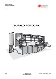
BUFALO RONDOFIX<br />
� 1 <strong>Operating</strong>s <strong>Instructions</strong> Edition 22. November 2007<br />
Bufalo Rondofix V3.0
<strong>Operating</strong> <strong>Instructions</strong><br />
BUFALO Rondofix V3.0<br />
Index<br />
1. Preface.................................................................................................................................................... 6<br />
1.1. Safety precautions .............................................................................................................................. 7<br />
2. Description of equipment ........................................................................................................................ 8<br />
2.1. Pupose ................................................................................................................................................ 8<br />
2.1.1. General view ................................................................................................................................ 8<br />
2.1.2. Intended purpose ......................................................................................................................... 9<br />
2.1.3. Responsabilities........................................................................................................................... 9<br />
2.2. Technical data................................................................................................................................... 10<br />
2.2.1. Dimensions ................................................................................................................................10<br />
2.2.2. Weight........................................................................................................................................ 11<br />
2.2.3. Electrical data ............................................................................................................................ 11<br />
2.2.4. Oils, lubricants ........................................................................................................................... 11<br />
2.2.5. Noise emission........................................................................................................................... 11<br />
2.2.6. Ambient conditions..................................................................................................................... 11<br />
2.3. Accessories....................................................................................................................................... 12<br />
3. Security ................................................................................................................................................. 13<br />
3.1. Mandatory reading ............................................................................................................................ 13<br />
3.1.1. Responsibilities .......................................................................................................................... 13<br />
3.1.2. Safety references....................................................................................................................... 13<br />
3.1.3.......................................................................................................................................................... 13<br />
3.1.4. References................................................................................................................................. 14<br />
3.1.5. Meaning of the symbols ............................................................................................................. 14<br />
3.2. Personal classification....................................................................................................................... 15<br />
3.2.1. <strong>Operating</strong> personnel (instructed in control)................................................................................ 15<br />
3.2.2. <strong>Operating</strong> personnel (not instructed in control).......................................................................... 15<br />
3.2.3. Maintenance personnel.............................................................................................................. 15<br />
3.2.4. Service personnel ...................................................................................................................... 15<br />
3.3. Danger zones.................................................................................................................................... 16<br />
3.3.1. Danger zone 1: Delivery station................................................................................................. 16<br />
3.3.2. Danger zone 2: Gluing unit ........................................................................................................ 16<br />
3.3.3. Gefahrenzone 3: Electrics cabinet............................................................................................. 17<br />
3.3.4. Danger zone 4: Cutting station .................................................................................................. 17<br />
3.3.5. Danger zone 5: Paper infeed..................................................................................................... 17<br />
3.4. Positions of the emergency stop switches ........................................................................................ 18<br />
3.5. General safety rules .......................................................................................................................... 19<br />
4. Layout and function .............................................................................................................................. 21<br />
4.1. General layout................................................................................................................................... 21<br />
4.2. Functional principle ........................................................................................................................... 21<br />
4.3. Subassemblies.................................................................................................................................. 22<br />
4.3.1. Infeed station ............................................................................................................................. 22<br />
4.3.2. Cutting station ............................................................................................................................ 23<br />
4.3.3. Fixing station.............................................................................................................................. 24<br />
4.3.4. Gluing station ............................................................................................................................. 25<br />
4.3.5. Pressing station ......................................................................................................................... 26<br />
4.3.6. Conveying system...................................................................................................................... 27<br />
4.3.7. Delivery station .......................................................................................................................... 28<br />
4.3.8. Paper gripper ............................................................................................................................. 29<br />
4.3.9. Dust bag..................................................................................................................................... 30<br />
4.3.10. Controls .................................................................................................................................. 31<br />
4.3.11. Control unit ............................................................................................................................. 32<br />
� 2 <strong>Operating</strong>s <strong>Instructions</strong> Edition 22. November 2007<br />
Bufalo Rondofix V3.0
<strong>Operating</strong> <strong>Instructions</strong><br />
BUFALO Rondofix V3.0<br />
5. Controls and operating modes.............................................................................................................. 33<br />
5.1. Commissioning the control system ................................................................................................... 33<br />
5.1.1. Turning-on the main switch........................................................................................................ 33<br />
5.1.2. Turning-on the main switch ................................................................................................... 34<br />
5.1.3. Switching-on the drives.............................................................................................................. 34<br />
5.2. Control unit........................................................................................................................................ 35<br />
5.3. <strong>Operating</strong> modes............................................................................................................................... 36<br />
5.3.1. Manual operation ....................................................................................................................... 36<br />
5.3.2. Semiautomatic operation ........................................................................................................... 36<br />
5.3.3. Automatic operation................................................................................................................... 36<br />
5.4. Emergency stopping ......................................................................................................................... 37<br />
5.4.1. Linking other equipment............................................................................................................. 37<br />
6. Commissioning ..................................................................................................................................... 38<br />
6.1. Introduction........................................................................................................................................ 38<br />
6.1.1. Personnel, qualification.............................................................................................................. 38<br />
6.1.2. Technical documentation........................................................................................................... 38<br />
6.1.3. Technical documentation........................................................................................................... 38<br />
6.2. Erecting and testing the machine...................................................................................................... 39<br />
6.2.1. Putting the machine into operation ............................................................................................ 39<br />
6.2.2. Testing the function.................................................................................................................... 39<br />
6.2.3. Acceptance certificate................................................................................................................ 39<br />
7. Operation .............................................................................................................................................. 40<br />
7.1. Control Panel Description ................................................................................................................. 40<br />
7.1.1. „Advance Reverse“ button ......................................................................................................... 40<br />
7.1.2. „Advance Forward“ button ......................................................................................................... 40<br />
7.1.3. „Fixer Forward“ button“ .............................................................................................................. 40<br />
7.1.4. „Fixer Reverse“ button ............................................................................................................... 41<br />
7.1.5. „Raise Press“ Button.................................................................................................................. 41<br />
7.1.6. „Lower Press“ Button ................................................................................................................. 41<br />
7.1.7. „Insert Lining or Cover“ Button................................................................................................... 41<br />
7.1.8. „No Lining or Cover“ Button ....................................................................................................... 41<br />
7.1.9. „Pusher“ Button.......................................................................................................................... 41<br />
7.1.10. „Programme Input“ Button...................................................................................................... 41<br />
7.1.11. „Mode Type Select“ Button .................................................................................................... 41<br />
7.1.12. „Start“ Button .......................................................................................................................... 42<br />
7.2. Switching On the Control System ..................................................................................................... 42<br />
7.3. Operational Mode Selection.............................................................................................................. 43<br />
7.3.1. Manual Operation ...................................................................................................................... 43<br />
7.3.2. Semi or Full Automatic Operation.............................................................................................. 44<br />
7.4. Programme Input .............................................................................................................................. 46<br />
7.4.1. System Settings ......................................................................................................................... 46<br />
7.4.2. Operational Parameters for Prod............................................................................................... 48<br />
7.5. Mechanical adjustments.................................................................................................................... 50<br />
7.5.1. Adjusting the book and glue thickness of the side gluing rollers ............................................... 50<br />
7.5.2. Adjusting the press stroke.......................................................................................................... 52<br />
7.5.3. Paper gripper ............................................................................................................................. 53<br />
7.5.4. Magnetic pusher ........................................................................................................................ 53<br />
7.5.5. Fitting the gauzing station.......................................................................................................... 54<br />
7.5.6. Feed adjustment for gauze or folding station............................................................................. 55<br />
7.5.7. Changing plates for cold and hot glue ....................................................................................... 56<br />
7.6. Error Messages and their Correction ................................................................................................ 57<br />
7.6.1. Control Voltage miss.................................................................................................................. 57<br />
7.6.2. Set V-min ................................................................................................................................... 57<br />
7.6.3. Programme Number .................................................................................................................. 58<br />
7.6.4. Hydraulics and Motors ............................................................................................................... 58<br />
� 3 <strong>Operating</strong>s <strong>Instructions</strong><br />
Bufalo Rondofix V3.0<br />
Edition 22. November 2007
<strong>Operating</strong> <strong>Instructions</strong><br />
BUFALO Rondofix V3.0<br />
7.6.5. Advance Front............................................................................................................................ 58<br />
7.6.6. Advance Rear ............................................................................................................................ 59<br />
7.6.7. Fixer Front.................................................................................................................................. 59<br />
7.6.8. Fixer Rear .................................................................................................................................. 59<br />
7.6.9. Press Down................................................................................................................................60<br />
7.6.10. Safety Shear Cutter................................................................................................................ 60<br />
7.6.11. Safety Glue Unit & Press........................................................................................................ 60<br />
7.6.12. Safety Delivery Station ........................................................................................................... 61<br />
7.6.13. Cover Control ......................................................................................................................... 61<br />
7.6.14. Cover Missing......................................................................................................................... 61<br />
7.6.15. Ejection................................................................................................................................... 62<br />
7.6.16. Delivery Station ...................................................................................................................... 62<br />
7.6.17. Light curtain............................................................................................................................ 63<br />
7.6.18. Safety ejection........................................................................................................................ 63<br />
8. Maintenance ......................................................................................................................................... 65<br />
8.1. Introduction........................................................................................................................................ 65<br />
8.2. Oils, lubricants................................................................................................................................... 65<br />
8.2.1. Oils, lubricants ........................................................................................................................... 65<br />
8.3. Maintenance schedule ...................................................................................................................... 66<br />
8.3.1. Cleaning shafts for gluing rollers ............................................................................................... 66<br />
8.3.2. Lubricating the Cardan shaft...................................................................................................... 67<br />
9. Servicing ............................................................................................................................................... 68<br />
9.1. Adjusting cutter clearance................................................................................................................. 68<br />
9.1.1. Clearance from plate.................................................................................................................. 68<br />
9.1.2. Clearance from back rest........................................................................................................... 69<br />
9.2. Cleaning the cooler ........................................................................................................................... 70<br />
9.3. Adjusting limit switches ..................................................................................................................... 71<br />
9.3.1. Right-hand limit switch ............................................................................................................... 71<br />
9.3.2. Left-hand limit switch ................................................................................................................. 72<br />
9.4. Adjusting the chain tensioner............................................................................................................ 73<br />
9.5. Limiting the press plate opening ....................................................................................................... 74<br />
9.6. Plate adjustment ............................................................................................................................... 75<br />
9.7. Adjusting the feed piston................................................................................................................... 76<br />
9.8. Ejector speed .................................................................................................................................... 77<br />
9.9. Brake adjustment .............................................................................................................................. 78<br />
9.10. Height adjustment of the gluing unit.................................................................................................. 79<br />
9.11. Interlocking........................................................................................................................................ 80<br />
10. Decommissioning, storage ................................................................................................................... 81<br />
10.1. Introduction........................................................................................................................................ 81<br />
10.1.1. Personnel, qualification .......................................................................................................... 81<br />
10.1.2. Storage conditions.................................................................................................................. 81<br />
10.2. Storage lasting more than six months............................................................................................... 81<br />
10.2.1. Preparations ........................................................................................................................... 81<br />
10.2.2. Maintenance during storage................................................................................................... 81<br />
11. Packing and transport........................................................................................................................... 82<br />
11.1. Preparations...................................................................................................................................... 82<br />
11.2. Packing.............................................................................................................................................. 82<br />
11.3. Transport........................................................................................................................................... 83<br />
11.3.1. Data for transportation............................................................................................................ 83<br />
11.3.2. Fixing points ........................................................................................................................... 83<br />
11.3.3. Transport by fork-lift ............................................................................................................... 84<br />
� 4 <strong>Operating</strong>s <strong>Instructions</strong> Edition 22. November 2007<br />
Bufalo Rondofix V3.0
<strong>Operating</strong> <strong>Instructions</strong><br />
BUFALO Rondofix V3.0<br />
12. Disposal ................................................................................................................................................ 85<br />
12.1. Introduction........................................................................................................................................ 85<br />
12.1.1. Personnel, qualification .......................................................................................................... 85<br />
12.2. Preparations for disposal .................................................................................................................. 86<br />
� 5 <strong>Operating</strong>s <strong>Instructions</strong> Edition 22. November 2007<br />
Bufalo Rondofix V3.0
<strong>Operating</strong> <strong>Instructions</strong><br />
BUFALO Rondofix V3.0<br />
1. Preface<br />
These operating instructions were issued in September 1998<br />
Updating status<br />
Section Title Date<br />
1 Preface 1 st edition 9/1998<br />
2 Description of equipment 1 st edition 9/1998<br />
3 Security 1 st edition 9/1998<br />
4 Layout and function 1 st edition 9/1998<br />
5 Controls and operating modes 2 st edition 3/2001<br />
6 Installation and commissioning 2 st edition 3/2001<br />
7 Operation 2 st edition 3/2001<br />
8 Maintenance 1 st edition 9/1998<br />
9 Servicing 1 st edition 9/1998<br />
10 Storage 1 st edition 9/1998<br />
11 Transport and packing 1 st edition 9/1998<br />
12 Disposal 1 st edition 9/1998<br />
Copyright © W. <strong>Gantenbein</strong> Maschinenbau <strong>GmbH</strong><br />
Subject to technical alterations without notification.<br />
No part of this documentation may be stored electronically, transferred or duplicated in any way<br />
without the prior approval in writing of W. <strong>Gantenbein</strong> Maschinenbau <strong>GmbH</strong>. This applies also to<br />
photocopying, photographing, and recording on magnetic or other data carriers, though it is not<br />
restricted to the aforenamed reproduction methods. Non-compliance will entail liability for damages.<br />
� 6 <strong>Operating</strong>s <strong>Instructions</strong> Edition 22. November 2007<br />
Bufalo Rondofix V3.0
<strong>Operating</strong> <strong>Instructions</strong><br />
BUFALO Rondofix V3.0<br />
1.1. Safety precautions<br />
The BUFALO RONDOFIX may be operated, maintained and serviced only by instructed<br />
personnel possessing the necessary technical qualifications.<br />
The operator is responsible for all persons involved being appropriately trained.. Further<br />
details is situated in the chapters 2.<br />
The firm of W. <strong>Gantenbein</strong> Maschinenbau <strong>GmbH</strong> declines all liability for any damage resulting<br />
from failure to fulfill these conditions.<br />
Before commissioning the BUFALO-RONDOFIX, Section 3 and the security instructions<br />
contained in it must have been read and understood.<br />
� 7 <strong>Operating</strong>s <strong>Instructions</strong> Edition 22. November 2007<br />
Bufalo Rondofix V3.0
<strong>Operating</strong> <strong>Instructions</strong><br />
BUFALO Rondofix V3.0<br />
2. Description of equipment<br />
2.1. Pupose<br />
Brief description: This section defines the intended purpose of the equipment and<br />
provides an overview of the performance scope, technical data and accessories of the<br />
BUFALO RONDOFIX.<br />
2.1.1. General view<br />
9<br />
8<br />
Fig. 1 General view<br />
1<br />
2<br />
1. Infeed station<br />
2. Cutting station<br />
3. Fixing station<br />
4. Control unit<br />
5. Gluing station<br />
6. Pressing station (optionally with folding station/gauzing station/cover station)<br />
7. Delivery station<br />
8. Circulating containers<br />
9. Dust bag<br />
� 8 <strong>Operating</strong>s <strong>Instructions</strong> Edition 22. November 2007<br />
Bufalo Rondofix V3.0<br />
3<br />
4<br />
5<br />
6<br />
7
<strong>Operating</strong> <strong>Instructions</strong><br />
BUFALO Rondofix V3.0<br />
2.1.2. Intended purpose<br />
The BUFALO RONDOFIX is intended for casing-in, i.e. folding or gauzing books<br />
brochures, blocks and other pressed, stacked or bound materials.<br />
Indication<br />
If the machine is used for any other than the purpose defined here without the<br />
written approval of the maker, or if it is operated outside its technical limits (see<br />
Technical Data), the maker will accept no liability for any damage or injury resulting<br />
therefrom.<br />
2.1.3. Responsabilities<br />
• Personnel<br />
It is the operator's responsibility that everyone charged with the operation,<br />
maintenance or servicing of the BUFALO RONDOFIX has read and understood<br />
the relevant parts of these operating instructions.<br />
• Instruction and training<br />
The BUFALO RONDOFIX may be operated, maintained and serviced only by<br />
instructed personnel having the necessary technical qualifications. The operator is<br />
responsible for organizing and holding the necessary instruction courses.<br />
• Security<br />
The BUFALO RONDOFIX is equipped with the necessary interlocks and safety<br />
devices in accordance with international regulations. Nevertheless the machine<br />
may present dangers if the safety precautions set out in Section 3 are not followed.<br />
These precautions and the safety-relevant instructions in the individual sections<br />
must be observed meticulously by the operator and the users. In particular the<br />
machine operator is responsible for the protection of persons and the prevention of<br />
material damage.<br />
� 9 <strong>Operating</strong>s <strong>Instructions</strong> Edition 22. November 2007<br />
Bufalo Rondofix V3.0
<strong>Operating</strong> <strong>Instructions</strong><br />
BUFALO Rondofix V3.0<br />
2.2. Technical data<br />
2.2.1. Dimensions<br />
2020<br />
730<br />
� 10 <strong>Operating</strong>s <strong>Instructions</strong> Edition 22. November 2007<br />
Bufalo Rondofix V3.0<br />
5110<br />
3410<br />
Fig.2 Dimensions of the BUFALO RONDOFIX<br />
650<br />
3000<br />
Fig. 3 Dimensions of the dust bag<br />
770
<strong>Operating</strong> <strong>Instructions</strong><br />
BUFALO Rondofix V3.0<br />
2.2.2. Weight<br />
Machine ca. 2100 kg<br />
Dust bag ca. 25 kg (empty)<br />
2.2.3. Electrical data<br />
Power supply Total 17 KW, 40 A<br />
Voltage 3 x 400 V<br />
Connecting leads L1, L2, L3, N, PE<br />
Frequency 50 Hz<br />
Current (fused by customer) 40 A<br />
Power max. 20 KW<br />
2.2.4. Oils, lubricants<br />
Oil BP Bartran SHF-S 46 / Blaser HVLP 46<br />
2.2.5. Noise emission<br />
The noise level ranges up to 75 dBA<br />
2.2.6. Ambient conditions<br />
Ambient temperature 10 - 40°C<br />
Air humidity 0 - 90 %<br />
� 11 <strong>Operating</strong>s <strong>Instructions</strong> Edition 22. November 2007<br />
Bufalo Rondofix V3.0
<strong>Operating</strong> <strong>Instructions</strong><br />
BUFALO Rondofix V3.0<br />
2.3. Accessories<br />
>25 kg<br />
Gauzing or folding station<br />
Suction feeder<br />
Accessory parts weighing more than 25 kg or of bulky shape must be fitted<br />
by two persons.<br />
The gauzing and folding station accessories and the suction feeder each<br />
weigh more than 25 kg.<br />
� 12 <strong>Operating</strong>s <strong>Instructions</strong> Edition 22. November 2007<br />
Bufalo Rondofix V3.0
<strong>Operating</strong> <strong>Instructions</strong><br />
BUFALO Rondofix V3.0<br />
3. Security<br />
Brief description: This section explains the safety concept of the BUFALO<br />
RONDOFIX. It defines the responsibilities of the operator and the security<br />
directives stated in these instructions.<br />
3.1. Mandatory reading<br />
Section 3 must be read by all persons involved in the installation, operation, maintenance and<br />
servicing of thr BUFALO RONDOFIX.<br />
3.1.1. Responsibilities<br />
The operator is responsible that all persons charged with the operation, maintenance<br />
or servicing of the BUFALO RONDOFIX have read and understood the relevant parts<br />
of these operating instructions<br />
The BUFALO RONDOFIX may be operated, maintained and serviced only by<br />
instructed personnel having the necessary technical qualifications. The operator is<br />
responsible for organizing and holding the necessary instruction courses.<br />
The operator is in addition responsible for:<br />
• keeping unauthorized persons away from the BUFALO RONDOFIX;<br />
• instructing the personnel about the potential risks and dangers when installing,<br />
operating, maintaining or servicing the BUFALO RONDOFIX as described in these<br />
instructions;<br />
• the strict observance of the technical specifications and safety instructions set out<br />
in Section 2.2 (Technical Data).<br />
3.1.2. Safety references<br />
3.1.3.<br />
The safety references that follow draw attention to the various danger levels and<br />
important technical requirements in the individual sections.<br />
Dangers possibly causing serious injuries or death.<br />
Dangers likely to cause light to medium injuries, substantial material<br />
damage or environmental offence.<br />
� 13 <strong>Operating</strong>s <strong>Instructions</strong> Edition 22. November 2007<br />
Bufalo Rondofix V3.0
<strong>Operating</strong> <strong>Instructions</strong><br />
BUFALO Rondofix V3.0<br />
3.1.4. References<br />
References in the form shown below draw attention to technical requirements and tips<br />
in the individual sections.<br />
3.1.5. Meaning of the symbols<br />
Indication<br />
<strong>Instructions</strong> on handling or use. Failure to follow them may lead to<br />
troubles or minor material damage.<br />
The following symbols are used in the operating instructions and on the machine.<br />
They mean:<br />
Warning: dangerous voltage<br />
Warning: hot surface<br />
Warning: injury to hands<br />
Warning: strong noise emission<br />
� 14 <strong>Operating</strong>s <strong>Instructions</strong> Edition 22. November 2007<br />
Bufalo Rondofix V3.0
<strong>Operating</strong> <strong>Instructions</strong><br />
BUFALO Rondofix V3.0<br />
3.2. Personal classification<br />
Depending on its training and authorization the personnel is classified as operational,<br />
maintenance and servicing. The operating personnel is subdivided into two categories:<br />
3.2.1. <strong>Operating</strong> personnel (instructed in control)<br />
The operating personnel may operate the BUFALO RONDOFIX in the automatic<br />
mode, which involves the following activities:<br />
• feeding the machine with unbound materials and removing the bound materials;<br />
• setting stops;<br />
• using the control system in the operating mode (switching-on, starting, program<br />
selection etc.);<br />
• cleaning<br />
3.2.2. <strong>Operating</strong> personnel (not instructed in control)<br />
The operating personnel may operate the BUFALO RONDOFIX in the automatic<br />
mode, involving the following activities:<br />
• feeding the machine with unbound materials and removing the bound materials;<br />
• cleaning.<br />
3.2.3. Maintenance personnel<br />
The maintenance personnel may operate the BUFALO RONDOFIX in the normal<br />
mode and in addition perform maintenance tasks necessary to ensure trouble-free<br />
operation. Maintenance includes the following tasks among others:<br />
• lubricating chains and Cardan shaft<br />
• checking the oil level.<br />
• all tasks described in the section on maintenance.<br />
To be able to maintain the BUFALO RONDOFIX the maintenance personnel must<br />
have been instructed by a co-worker or an experienced and responsible employee of<br />
the plant operator.<br />
3.2.4. Service personnel<br />
The service personnel may operate the BUFALO RONDOFIX in the normal mode and<br />
perform maintenance and servicing work.<br />
• All activities described in the section on servicing.<br />
The BUFALO RONDOFIX may be serviced only by trained employees of W. <strong>Gantenbein</strong><br />
Maschinenbau <strong>GmbH</strong>, a representative of this firm or trained employees of the<br />
plant operator with equivalent proficiency.<br />
For working on electrical components a training as master electrician or equivalent is<br />
necessary.<br />
� 15 <strong>Operating</strong>s <strong>Instructions</strong> Edition 22. November 2007<br />
Bufalo Rondofix V3.0
<strong>Operating</strong> <strong>Instructions</strong><br />
BUFALO Rondofix V3.0<br />
3.3. Danger zones<br />
The critical danger zones are shown in the illustration below.<br />
Fig. 4 Danger zones<br />
3.3.1. Danger zone 1: Delivery station<br />
• Danger from moving mechanical parts.<br />
3.3.2. Danger zone 2: Gluing unit<br />
5<br />
� 16 <strong>Operating</strong>s <strong>Instructions</strong> Edition 22. November 2007<br />
Bufalo Rondofix V3.0<br />
4<br />
Danger from moving mechanical parts.<br />
Do not reach under the protective hood.<br />
Danger from glue temperature up to 200°C.<br />
Do not reach into the gluing unit during operation.<br />
3<br />
2<br />
1
<strong>Operating</strong> <strong>Instructions</strong><br />
BUFALO Rondofix V3.0<br />
Danger from possible vapours.<br />
3.3.3. Gefahrenzone 3: Electrics cabinet<br />
Read and note the safety instructions of the glue supplier.<br />
Suctioning or other precautions may be necessary to avoid possible<br />
danger to health.<br />
Warning: Voltage<br />
3.3.4. Danger zone 4: Cutting station<br />
3.3.5. Danger zone 5: Paper infeed<br />
Turn off the main switch before working on the electrical installation.<br />
Considerable noise is set up when cutting and roughening the book<br />
spines.<br />
Always wear hearing protection while working.<br />
Warning: Paper gripper moves down.<br />
Do not reach into the path of the downcoming gripper.<br />
� 17 <strong>Operating</strong>s <strong>Instructions</strong> Edition 22. November 2007<br />
Bufalo Rondofix V3.0
<strong>Operating</strong> <strong>Instructions</strong><br />
BUFALO Rondofix V3.0<br />
3.4. Positions of the emergency stop switches<br />
The positions of the emergency stop switches are shown in the illustration below.<br />
Fig. 5 Emergency stop switches<br />
1. Emergency stop switch at infeed station<br />
2. Emergency stop switch on control unit<br />
2<br />
� 18 <strong>Operating</strong>s <strong>Instructions</strong> Edition 22. November 2007<br />
Bufalo Rondofix V3.0<br />
1
<strong>Operating</strong> <strong>Instructions</strong><br />
BUFALO Rondofix V3.0<br />
3.5. General safety rules<br />
The following rules must be strictly observed.<br />
• Use as intended<br />
See subsection 2.1.2<br />
• Maker's specifications<br />
The application specifications include also the observance of the regulations for<br />
commissioning, maintaining and servicing the BUFALO RONDOFIX.<br />
• Personnel training<br />
The BUFALO RONDOFIX may be installed, operated (commissioned), maintained and<br />
serviced only by trained personnel. These people must have been instructed about the<br />
dangers associated with the machine.<br />
• Delimitation of responsibility<br />
The responsibilities and competences must be established clearly prior to installation,<br />
operation, maintenance or servicing work, and they must be adhered to under all<br />
Circumstances.<br />
• Misuse<br />
It is absolutely wrong to operate the BUFALO RONDOFIX in such a way that injury to<br />
persons or material damage may ensue.<br />
• Inaccessibility for unauthorized or untrained persons<br />
It is the operator's responsibility that the BUFALO RONDOFIX can be used only by trained<br />
persons.<br />
• Impermissible modifications<br />
Modifications or design alterations detrimental to the security or reliability of the BUFALO<br />
RONDOFIX are not allowed. W. <strong>Gantenbein</strong> Maschinenbau <strong>GmbH</strong> must be contacted<br />
before attempting any modifications.<br />
• Registration of modifications<br />
The operator is under obligation to notify W. <strong>Gantenbein</strong> Maschinenbau <strong>GmbH</strong> at once of<br />
modifications to the BUFALO RONDOFIX, especially if the security or reliability of the<br />
machine might be affected.<br />
• Maintenance obligation<br />
The operator must ensure that the BUFALO RONDOFIX is operated only under admissible<br />
conditions and in perfect state.<br />
• Working area<br />
The operator must ensure that the BUFALO RONDOFIX is freely accessible on all sides for<br />
all necessary work.<br />
� 19 <strong>Operating</strong>s <strong>Instructions</strong> Edition 22. November 2007<br />
Bufalo Rondofix V3.0
<strong>Operating</strong> <strong>Instructions</strong><br />
BUFALO Rondofix V3.0<br />
• Transport and installation<br />
The BUFALO RONDOFIX may be transported only in its original packing and lifted only by<br />
the points provided. Installation must be performed exclusively by technically qualified<br />
personnel. The relevant installation instructions must be followed strictly.<br />
• Switching-off<br />
The BUFALO RONDOFIX must be switched off <strong>complete</strong>ly for all maintenance and<br />
servicing work, to ensure that all parts of it are dead whilst working.<br />
• Removing safety devices<br />
Safety devices may be removed only when the machine is switched off and its power<br />
supply cut off. The safety devices must be properly fitted again before restoring the power<br />
supply.<br />
• Checks after maintenance or servicing<br />
After any installation, maintenance or servicing work all safety circuits (e.g. interlocks) must<br />
be checked to ensure that they function properly. Above all, after electrical installation or<br />
servicing the safety provisions must be tested (e.g. earthing, insulation resistance etc.). The<br />
BUFALO RONDOFIX may be put back into operation only after successful checking.<br />
• Connections to the BUFALO RONDOFIX<br />
Electrical connecting leads must be protected against all kinds of mechanical damage. The<br />
leads must affect neither the security nor the reliability of the machine, nor working on it.<br />
• Organizational measures<br />
These operating instructions must be kept accessible at all times at a place near to the<br />
BUFALO RONDOFIX.<br />
• Specific safety regulations<br />
Local regulations and specific safety regulations applying to industrial equipment must<br />
likewise be observed when operating the BUFALO RONDOFIX.<br />
� 20 <strong>Operating</strong>s <strong>Instructions</strong> Edition 22. November 2007<br />
Bufalo Rondofix V3.0
<strong>Operating</strong> <strong>Instructions</strong><br />
BUFALO Rondofix V3.0<br />
4. Layout and function<br />
4.1. General layout<br />
Brief description: This section explains the safety concept of the BUFALO<br />
RONDOFIX. It defines the responsibilities of the operator and the security<br />
directives stated in these instructions.<br />
The BUFALO RONDOFIX consists essentially of two associated subsystems:<br />
• Production machine<br />
• Dust bag<br />
9<br />
8<br />
1<br />
2<br />
Fig. 6 Overall view<br />
1. Infeed station<br />
2. Cutting station<br />
3. Fixing station<br />
4. Control unit<br />
5. Gluing station<br />
6. Pressing station (optionally with folding station/gauzing station/cover station)<br />
7. Delivery station<br />
8. Circulating container<br />
9. Dust bag<br />
4.2. Functional principle<br />
The unbound book block or unbound brochure is led to the gripping jaws, thereby actuating a<br />
contact that triggers in the correct sequence all motions needed for the working operation.<br />
After inserting the first brochure the start key must then be pressed, likewise after the<br />
economy circuit responds.<br />
� 21 <strong>Operating</strong>s <strong>Instructions</strong> Edition 22. November 2007<br />
Bufalo Rondofix V3.0<br />
3<br />
4<br />
5<br />
6<br />
7
<strong>Operating</strong> <strong>Instructions</strong><br />
BUFALO Rondofix V3.0<br />
6<br />
4.3. Subassemblies<br />
4.3.1. Infeed station<br />
At this station the paper to be bound is placed in the paper gripper.<br />
59 57 55 53 51 49 47 45 43 41 39 37 35 33 31 29 27 25 23 21 19 17 15 13 9 7<br />
5<br />
4<br />
Fig. 7 Infeed station<br />
� 22 <strong>Operating</strong>s <strong>Instructions</strong> Edition 22. November 2007<br />
Bufalo Rondofix V3.0<br />
3<br />
1. Start trigger 4. Inclination adjustment<br />
2. Emergency stop switch 5. Cutting depth adjustment<br />
3. Infeed table 6. Fixing lever<br />
6<br />
5<br />
4<br />
Abbildung 8 Cutting depth adjustment<br />
1<br />
Infeed table with sensor-controlled start triggering. At this station the cutting depth is<br />
adjusted from 0 mm to 5.6 mm for stitched book blocks, and the inclination is adjusted<br />
too.<br />
2
<strong>Operating</strong> <strong>Instructions</strong><br />
BUFALO Rondofix V3.0<br />
4.3.2. Cutting station<br />
At this station the book or brochure spines are routed off to the preadjusted height.<br />
4<br />
Fig. 9 Cutting station<br />
1. Adjusting screw<br />
2. Cover plate<br />
3. Grinding wheel<br />
4. Cutter<br />
5. Cutter cover<br />
3<br />
The spine cutter consists of a hard metal cutter blade with overarm. The fold is cut<br />
away and then roughened by the grinding wheel and the fibres felted.<br />
� 23 <strong>Operating</strong>s <strong>Instructions</strong> Edition 22. November 2007<br />
Bufalo Rondofix V3.0<br />
2<br />
5<br />
1
<strong>Operating</strong> <strong>Instructions</strong><br />
BUFALO Rondofix V3.0<br />
4.3.3. Fixing station<br />
The spine and end piece of the book or brochure to be bound are provided with<br />
regular, crosswise dovetail cuts in the fixing unit.<br />
59 57 55 53 51 49 47 45 43 41 39 37 35 33 31 29 27 25 23 21 19 17 15 13 9<br />
Fig 10 Fixing station<br />
1. Cutter<br />
2. Height adjustment<br />
3. Cover plate<br />
3<br />
2<br />
� 24 <strong>Operating</strong>s <strong>Instructions</strong> Edition 22. November 2007<br />
Bufalo Rondofix V3.0<br />
1<br />
The fixing unit cuts crosswise grooves .8 mm wide into the spine, adjustable in depth<br />
up to 1 mm, into which the glue penetrates like a thread. This gives a strengthened<br />
binding.<br />
7
<strong>Operating</strong> <strong>Instructions</strong><br />
BUFALO Rondofix V3.0<br />
4.3.4. Gluing station<br />
The gluing station serves to apply glue onto the spine of the book or brochure.<br />
12<br />
11<br />
1 2 3 4 5 6 7<br />
Fig. 11 Gluing station<br />
1. Glue thickness adjustment for gluing roller 1<br />
2. Gluing roller 1<br />
3. Glue thickness adjustment for gluing roller 2<br />
4. Gluing roller 2<br />
5. Glue wiper adjustment<br />
6. Height adjustment for gluing unit<br />
7. Height adjustment for side gluing<br />
8. Side gluing roller<br />
9. Gluing wheel<br />
10. Heating for hot glue (optional)<br />
11. Lifting device for glue pot<br />
12. Thermostat for glue pot (for hot glue heating)<br />
• Cold gluing<br />
The glue is applied by two rollers for the spine and two side gluing rollers.<br />
• Hot gluing<br />
There is a choice between a one-piece and a two-piece glue pot. With two-piece<br />
glue pots it is possible to use different glues simultaneously for the spine and<br />
sides. The glue is kept at the right temperature by thermostats.<br />
� 25 <strong>Operating</strong>s <strong>Instructions</strong> Edition 22. November 2007<br />
Bufalo Rondofix V3.0<br />
8<br />
9<br />
10
<strong>Operating</strong> <strong>Instructions</strong><br />
BUFALO Rondofix V3.0<br />
4.3.5. Pressing station<br />
The pressing station serves to press the books or brochures being produced<br />
(pressing-on the covers).<br />
3<br />
2<br />
59 57 55 53 51 49 47 45 43 41 39 37 35 33 31 29 27 25 23 21 19 17 15 13 9<br />
Fig. 12 Pressing station<br />
1. Front pressing plate<br />
2. Rear pressing plate<br />
3. Pressing table<br />
1<br />
7<br />
On the standard BUFALO RONDOFIX the covers are fed in manually and pressed on<br />
from below and the side by a hydraulic press. Pressing time may be varied between<br />
0.5 and 5 seconds by the control system. Thanks to the high pressing force of 100 kg,<br />
covers weighing up to 300 g can be handled without scoring.<br />
To press on a cover, first the lower pressing plate moves up and presses the cover<br />
against the spine. Then the front and rear pressing plates move together, pressing the<br />
cover against the side glue.<br />
� 26 <strong>Operating</strong>s <strong>Instructions</strong> Edition 22. November 2007<br />
Bufalo Rondofix V3.0
<strong>Operating</strong> <strong>Instructions</strong><br />
BUFALO Rondofix V3.0<br />
4.3.6. Conveying system<br />
The conveying system takes the finished books and brochures to the delivery station.<br />
3<br />
Fig. 13 Conveying system<br />
1. Hand wheel<br />
2. Conveying system<br />
3. Conveyor belt<br />
2<br />
59 57 55 53 51 49 47 45 43 41 39 37 35 33 31 29 27 25 23 21 19 17 15 13 9 7<br />
With the hand wheel the spacing of the conveying system is matched to the book<br />
width.<br />
The station has an ejection sensor that stops the machine if there is still a book in the<br />
paper gripper after passing the ejection.<br />
� 27 <strong>Operating</strong>s <strong>Instructions</strong> Edition 22. November 2007<br />
Bufalo Rondofix V3.0<br />
1
<strong>Operating</strong> <strong>Instructions</strong><br />
BUFALO Rondofix V3.0<br />
4.3.7. Delivery station<br />
The delivery station serves to dry the books or brochures.<br />
59 57 55 53 51 49 47 45 43 41 39 37 35 33 31 29 27 25 23 21 19 17 15 13 9 7<br />
4 3<br />
Fig. 14 Delivery station<br />
1. Heatable delivery (for cold glue only)<br />
2. Ejector<br />
3. Valve for heated delivery<br />
4. Counter (optical sensor))<br />
5. Safety hood<br />
On their way to the heated delivery the books are counted eelctronically. They are<br />
then positioned for drying standing on their spines.<br />
Fig. 15 Delivery station<br />
� 28 <strong>Operating</strong>s <strong>Instructions</strong> Edition 22. November 2007<br />
Bufalo Rondofix V3.0<br />
2<br />
1<br />
5<br />
In Fig. 10 the valve [3] is shown in the<br />
heating position for cold glue.
<strong>Operating</strong> <strong>Instructions</strong><br />
BUFALO Rondofix V3.0<br />
4.3.8. Paper gripper<br />
The circulating paper grippers take up the paper to bring it to the working stations.<br />
59 57 55 53 51 49 47 45 43 41 39 37 35 33 31 29 27 25 23 21 19 17 15 13 9<br />
1<br />
4<br />
Fig. 16 Paper gripper<br />
1. Gripper spacing adjustment<br />
2. Support<br />
3. Scale<br />
4. Spine length stop<br />
3<br />
7<br />
2<br />
� 29 <strong>Operating</strong>s <strong>Instructions</strong> Edition 22. November 2007<br />
Bufalo Rondofix V3.0<br />
1
<strong>Operating</strong> <strong>Instructions</strong><br />
BUFALO Rondofix V3.0<br />
4.3.9. Dust bag<br />
The dust bag takes up the suctioned paper wastes (shavings, dust etc.)<br />
3<br />
2<br />
1<br />
Abbildung 17 Suction hose<br />
1. Stand<br />
2. Waste bag<br />
3. Filter bag<br />
4. Suction hose<br />
� 30 <strong>Operating</strong>s <strong>Instructions</strong> Edition 22. November 2007<br />
Bufalo Rondofix V3.0<br />
4
<strong>Operating</strong> <strong>Instructions</strong><br />
BUFALO Rondofix V3.0<br />
4.3.10. Controls<br />
The controls shown below control and regulate all functions of the machine.<br />
1 2 3 4 5 6 7<br />
7 8 9<br />
ALARM<br />
SYST<br />
4 5 6<br />
SYST<br />
1 2 3<br />
Start<br />
ALARM<br />
+/– 0 .<br />
� 31 <strong>Operating</strong>s <strong>Instructions</strong> Edition 22. November 2007<br />
Bufalo Rondofix V3.0<br />
DEL<br />
ESC +1 MENU<br />
MOD<br />
SHIFT -1 ENTER<br />
Fig. 18 Controls<br />
1. Advance speed<br />
2. Main switch<br />
3. Control voltage switch-on/off<br />
4. Control unit<br />
5. Counter<br />
6. Emergency stop switch<br />
7. Thermostat control for hot gluing (optional)<br />
MAGELiS<br />
Stop
<strong>Operating</strong> <strong>Instructions</strong><br />
BUFALO Rondofix V3.0<br />
4.3.11. Control unit<br />
The control unit accommodates the display, operating and controls for the BUFALO<br />
RNDOFIX.<br />
ALARM<br />
ESC<br />
SHIFT<br />
+1<br />
SYST<br />
MOD<br />
-1<br />
� 32 <strong>Operating</strong>s <strong>Instructions</strong> Edition 22. November 2007<br />
Bufalo Rondofix V3.0<br />
MENU<br />
ALARM<br />
ENTER<br />
DEL<br />
7<br />
8 9<br />
4 5 6<br />
1 2 3<br />
+/– 0 .<br />
5 4<br />
3<br />
Fig. 19 Control unit<br />
1. Display<br />
2. Control key<br />
3. Numeric keypad<br />
4. Function keys<br />
5. Manual operation keys<br />
SYST<br />
1<br />
Start<br />
MAGELiS<br />
2<br />
Stop
<strong>Operating</strong> <strong>Instructions</strong><br />
BUFALO Rondofix V3.0<br />
5. Controls and operating modes<br />
Brief description: This section explains the safety concept of the BUFALO<br />
RONDOFIX. It defines the responsibilities of the operator and the security<br />
directives stated in these instructions.<br />
5.1. Commissioning the control system<br />
1 2 3 4 5<br />
DEL<br />
ESC +1 MENU<br />
MOD<br />
SHIFT -1 ENTER<br />
ALARM<br />
SYST<br />
SYST<br />
ALARM<br />
MAGELiS<br />
7 8 9<br />
4 5 6<br />
1 2 3<br />
Start<br />
+/– 0 .<br />
Fig. 20 Control console<br />
1. Main switch<br />
2. Control voltage switch-on/off<br />
3. Control unit<br />
4. Counter<br />
5. Emergency stop switch<br />
The machine has a lockable main switch.<br />
Stop<br />
The main switch can be secured in the OFF position for servicing purposes, using up<br />
to 3 padlocks.<br />
5.1.1. Turning-on the main switch<br />
To put the machine into operation the main switch must be turned on. If it is secured<br />
with more than one padlock, these must be removed by the people who attached<br />
them.<br />
The main switch is turned on by turning it clockwise.<br />
� 33 <strong>Operating</strong>s <strong>Instructions</strong> Edition 22. November 2007<br />
Bufalo Rondofix V3.0
<strong>Operating</strong> <strong>Instructions</strong><br />
BUFALO Rondofix V3.0<br />
5.1.2. Turning-on the main switch<br />
After turning on the main switch the control voltage can be switched on by pressing<br />
the green button [2], though this is possible only if no emergency stop switch has been<br />
operated and the covering over the cutter is closed. Emergency stop switches once<br />
pressed are released by turning them.<br />
The green button [2] lights when the control voltage is switched on.<br />
5.1.3. Switching-on the drives<br />
Upon switching-on the control voltage the motors driving the various subunits are put<br />
into operation automatically.<br />
These drives are switched off automatically after running more than 5 minutes without<br />
load.<br />
The drives are switched on again automatically by operating a button or switch for<br />
manual or automatic operation on the control unit [3].<br />
� 34 <strong>Operating</strong>s <strong>Instructions</strong> Edition 22. November 2007<br />
Bufalo Rondofix V3.0
<strong>Operating</strong> <strong>Instructions</strong><br />
BUFALO Rondofix V3.0<br />
5.2. Control unit<br />
ALARM<br />
ESC<br />
SHIFT<br />
+1<br />
SYST<br />
MOD<br />
-1<br />
MENU<br />
ALARM<br />
ENTER<br />
� 35 <strong>Operating</strong>s <strong>Instructions</strong> Edition 22. November 2007<br />
Bufalo Rondofix V3.0<br />
DEL<br />
7<br />
8 9<br />
4 5 6<br />
1 2 3<br />
+/– 0 .<br />
5 4<br />
3<br />
SYST<br />
Fig. 21 Control unit<br />
1. Display<br />
2. Control keys<br />
3. Numeric keys<br />
4. Function keys<br />
5. Manual operation keys<br />
1<br />
Start<br />
MAGELiS<br />
For a full description of the functions see subsection 7.1: Control Unit.<br />
2<br />
Stop
<strong>Operating</strong> <strong>Instructions</strong><br />
BUFALO Rondofix V3.0<br />
5.3. <strong>Operating</strong> modes<br />
5.3.1. Manual operation<br />
In manual operation all subassemblies of the BUFALO RONDOFIX can be operated<br />
singly with the function keys [4] and manual operation keys[5] (for full details see<br />
Section 7).<br />
5.3.2. Semiautomatic operation<br />
In semiautomatic operation each movement of the machine must be triggered by<br />
pressing the starting key. In this way the machine cycle can be run through stepwise<br />
(for more details see Section 7).<br />
5.3.3. Automatic operation<br />
In automatic operation only the first cycle must be started by pressing the starting key<br />
after inserting the book. The next cycle is started automatically by inserting the second<br />
book. Readiness is signalled by the diode lighting in the starting key (for fully<br />
description see Section 7).<br />
� 36 <strong>Operating</strong>s <strong>Instructions</strong> Edition 22. November 2007<br />
Bufalo Rondofix V3.0
<strong>Operating</strong> <strong>Instructions</strong><br />
BUFALO Rondofix V3.0<br />
5.4. Emergency stopping<br />
Indication<br />
The emergency stop switch is effective in every operating mode. It serves to<br />
shut down the machine in dangerous situations. Every an emergency stop all<br />
subunits are without power.<br />
<strong>Operating</strong> the emergency stop switch cuts out the control voltage. This must be<br />
restored again after releasing the emergency stop switch by pressing the ON key.<br />
Opening the safety covers over the fixing station will also trigger an emergency stop.<br />
After closing the covers the control voltage must be switched on again.<br />
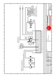
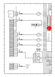
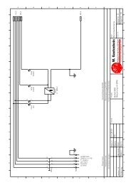
5.4.1. Linking other equipment<br />
If the EMERGENCY STOP circuit of other equipment is to be linked with the safety<br />
circuit of the BUFALO RONDOFIX, terminals have been provided for this. The<br />
connections are shown in the electrical diagram.<br />
The control system of the BUFALO RONDOFIX gives a pulse signal to other<br />
equipment.<br />
� 37 <strong>Operating</strong>s <strong>Instructions</strong> Edition 22. November 2007<br />
Bufalo Rondofix V3.0
<strong>Operating</strong> <strong>Instructions</strong><br />
BUFALO Rondofix V3.0<br />
6. Commissioning<br />
6.1. Introduction<br />
Brief description: This section provides information for successfully installing and<br />
commissioning. It deals with the erection, assembly and the first commissioning of the<br />
BUFALO RONDOFIX.<br />
It is the operator's responsibility that everyone involved in the installation of the BUFALO<br />
RONDOFIX has read and understood these operating instructions.<br />
The following personnel and technical qualifications are required for erecting, assembling and<br />
commissioning the machine.<br />
6.1.1. Personnel, qualification<br />
The work described in this section may be carried out only by authorized skilled<br />
personnel who have had appropriate technical training and can draw upon the<br />
necessary experience, or who have been suitably instructed by the operator.<br />
6.1.2. Technical documentation<br />
This equipment may pose dangers if the safety rules are not<br />
followed. See Section 3: Security.<br />
The following technical documentation is needed for erecting, assembling and<br />
commissioning the machine:<br />
• electrical diagram<br />
This may be found in your technical documentation.<br />
6.1.3. Technical documentation<br />
The following technical documentation is needed for erecting, assembling and<br />
commissioning the machine:<br />
• electrical diagram<br />
This may be found in your technical documentation.<br />
� 38 <strong>Operating</strong>s <strong>Instructions</strong> Edition 22. November 2007<br />
Bufalo Rondofix V3.0
<strong>Operating</strong> <strong>Instructions</strong><br />
BUFALO Rondofix V3.0<br />
6.2. Erecting and testing the machine<br />
Check the following points before commissioning:<br />
• Is the power cable intact and properly connected?<br />
Indication<br />
Check the rotation of the motors. The gluing rollers may be used for this. If<br />
they will not turn, the motor rotation needs reversing.<br />
• Has the power cable been laid covered and secured?<br />
• Are there no foreign materials on or at the machine'?<br />
• Check whether the paper grippers run properly and unobstructed.<br />
• Check whether the infeed station functions faultlessly and unobstructed.<br />
• Check whether the cutting station functions faultlessly and unobstructed.<br />
• Check whether the fixing station functions faultlessly and unobstructed.<br />
• Check whether the gluing station and gluing rollers function faultlessly and unobstructed.<br />
• Check whether the pressing station functions faultlessly and unobstructed.<br />
• Check whether the delivery station functions faultlessly and unobstructed.<br />
• If one of the stations malfunctions, see Section 7.6 Trouble Shooting and rectify the fault as<br />
instructed therein.<br />
6.2.1. Putting the machine into operation<br />
To commission the machine proceed as follows:<br />
• Schalten Sie den Hauptschalter ein.<br />
• Check the emergency stop switches and release them if necessary (see<br />
subsection 3.4).<br />
• Switch the machine on (see Section 5).<br />
• Switch the machine over to manual operation (see Section 7).<br />
• Test the door interlock circuit of the cutter/fixer and gluing station/press by opening<br />
the doors singly and closing them again. When any of these doors is opened the<br />
control must cut out and a fault must be signalled.<br />
6.2.2. Testing the function<br />
Check all functions according to Section 5 before considering the commissioning<br />
<strong>complete</strong>d and handing the machine over for normal operation.<br />
6.2.3. Acceptance certificate<br />
The acceptance certificate must be copied. Do not write on the original. See appendix.<br />
� 39 <strong>Operating</strong>s <strong>Instructions</strong> Edition 22. November 2007<br />
Bufalo Rondofix V3.0
<strong>Operating</strong> <strong>Instructions</strong><br />
BUFALO Rondofix V3.0<br />
7. Operation<br />
Brief description: This section shows by means of example how the BUFALO<br />
RONDOFIX is operated. All routine steps for production are described in detail..<br />
7.1. Control Panel Description<br />
Fig. 22 Control Panel<br />
ALARM<br />
ESC<br />
SHIFT<br />
+1<br />
SYST<br />
MOD<br />
7.1.1. „Advance Reverse“ button<br />
Button for manual operation.<br />
-1<br />
� 40 <strong>Operating</strong>s <strong>Instructions</strong> Edition 22. November 2007<br />
Bufalo Rondofix V3.0<br />
SYST<br />
MENU<br />
ALARM<br />
ENTER<br />
DEL<br />
7<br />
8 9<br />
4 5 6<br />
1 2 3<br />
+/– 0 .<br />
Start<br />
MAGELiS<br />
Pressing this key makes the press stroke up as long as the key is pressed. If the cover<br />
is open it will function only if the dual-palm buttons on the press are pressed<br />
simultaneously.<br />
7.1.2. „Advance Forward“ button<br />
Button for manual operation.<br />
Press this button and keep it depressed to run the advance forwards. The<br />
speed selector must be set to minimum, otherwise an error message will<br />
appear.<br />
7.1.3. „Fixer Forward“ button“<br />
Button for manual operation.<br />
Press this button and keep it depressed to run the fixer forwards.<br />
Stop
<strong>Operating</strong> <strong>Instructions</strong><br />
BUFALO Rondofix V3.0<br />
7.1.4. „Fixer Reverse“ button<br />
Button for manual operation<br />
Button for manual operation.<br />
Press this button and keep it depressed to run the fixer in reverse.<br />
7.1.5. „Raise Press“ Button<br />
Button for manual operation.<br />
Press this button and keep it depressed to raise the press. If the glue unit safety cover<br />
is open, this button only functions if the "two-hand button" under this safety cover is<br />
pressed simultaneously.<br />
7.1.6. „Lower Press“ Button<br />
Button for manual operation.<br />
Press this button and keep it depressed to lower the press.<br />
7.1.7. „Insert Lining or Cover“ Button<br />
Button for all operational modes.<br />
Press this button to start the lining advance, or to insert a cover.<br />
7.1.8. „No Lining or Cover“ Button<br />
Button for semi and fully automatic operational modes.<br />
Press this button to stop the next lining advance, or to stop the insert of another cover.<br />
This function is automatically reset.<br />
When the function is active, the built-in diode in the button lights<br />
7.1.9. „Pusher“ Button<br />
Button for all operational modes.<br />
Press this button to actuate the pusher for a cycle. In semi and fully automatic<br />
operational modes, this button only functions when the machine is not operating.<br />
7.1.10. „Programme Input“ Button<br />
Press this button to enter programme input mode. This command is only<br />
accepted while the machine is not in operation. During programming the machine<br />
cannot be operated, neither in manual nor in an automatic mode.<br />
7.1.11. „Mode Type Select“ Button<br />
Press this button to select the operational mode type, between manual,<br />
semi and fully automatic operational modes.<br />
In manual operation mode, the milling cutter, fixer and glue unit can be switched on<br />
and off.<br />
In semi and fully automatic operational modes, only the desired programme number<br />
can be entered.<br />
� 41 <strong>Operating</strong>s <strong>Instructions</strong> Edition 22. November 2007<br />
Bufalo Rondofix V3.0
<strong>Operating</strong> <strong>Instructions</strong><br />
BUFALO Rondofix V3.0<br />
7.1.12. „Start“ Button<br />
Button for all operational modes<br />
In semi and fully automatic operational modes, pressing this button starts the<br />
automatic cycle, or the semi-automatic cycle will be advanced one step.<br />
7.2. Switching On the Control System<br />
To put the machine into operation, first switch on the main switch on the control panel.<br />
Then actuate the control system by pressing the green luminous button. The control system is<br />
only active provided no emergency cut-off button has been pressed, and the milling cutter<br />
safety cover is closed. The emergency cut-off button can be disengaged by rotating it.<br />
The green luminous button lights when the control system is active.<br />
In cases of danger one of the emergency cut-off buttons must be pressed. After the<br />
malfunction has been eliminated, the pressed emergency cut-off button must be disengaged,<br />
and the open milling cutter cover closed, to allow the control system to be reactivated by<br />
pressing the green luminous button.<br />
When the main switch is engaged and the control system is not actuated, the blinking error<br />
message "No control voltage" appears on the control panel. This error message does not<br />
require any action at this point: it disappears automatically when the control system is<br />
actuated.<br />
Indication<br />
The first machine cycle must be made at minimum speed for operational<br />
reasons. Therefore, set the speed selector to minimum until the machine has<br />
<strong>complete</strong>d its first cycle. If this is forgotten, the machine will not carry out any<br />
forward advance, but instead the message "Set V-min" will be displayed. This<br />
error message does not require any action at this point: it disappears<br />
automatically when the start button, or the button which releases the forward<br />
advance, is released.<br />
If a forward advance is not <strong>complete</strong>d while in manual operation, the speed<br />
selector must be reset to minimum again.<br />
Indication<br />
After switching-on the control voltage the motors driving the various units are<br />
automatically started in staggered sequence.<br />
These drives are switched off automatically after running without load more<br />
than 5 minutes.<br />
The drives are switched on again automatically by operating a key or switch<br />
for manual or automatic operation.<br />
� 42 <strong>Operating</strong>s <strong>Instructions</strong> Edition 22. November 2007<br />
Bufalo Rondofix V3.0
<strong>Operating</strong> <strong>Instructions</strong><br />
BUFALO Rondofix V3.0<br />
7.3. Operational Mode Selection<br />
After the main switch is engaged, the control system returns to the same operational mode in<br />
which it was before it was switched off.<br />
To change the operational mode, press the "Operational Mode Select" button. The<br />
following is displayed:<br />
Manual Semi Auto<br />
← ↓ →<br />
Select the desired operational mode by pressing the corresponding arrow key.<br />
7.3.1. Manual Operation<br />
After manual operational mode is selected (see above), the following is displayed:<br />
Milling Cutter ON 0<br />
The cutter can now be actuated by pressing the "MOD" button and then inputting 0 or<br />
1 (on or off). The input must be concluded by pressing "Enter", to advance the<br />
programme and the following is displayed:<br />
Fixer ON 0<br />
The fixer can now be switched on or off like the milling cutter.<br />
The display then displays the following:<br />
Glue heater<br />
Off ← On ↓ Auto →<br />
The glue heater can now be switched off in manual operational mode (cold gluing) or<br />
left on continuously, or switched on and off according to the timer programme.<br />
At the same time, the programme advances and displays:<br />
Tip Glue Unit<br />
The glue unit can be held in the desired position by pressing the manual button. If the<br />
manual button is held for more than 1 sec, the glue unit remains in position after the<br />
manual button is released. Pressing the manual button again restarts the glue unit<br />
Indication<br />
To stop the glue unit <strong>complete</strong>ly, use an emergency cut-off button.<br />
To exit this mode, press the "Enter" button. The following is now displayed:<br />
� 43 <strong>Operating</strong>s <strong>Instructions</strong> Edition 22. November 2007<br />
Bufalo Rondofix V3.0
<strong>Operating</strong> <strong>Instructions</strong><br />
BUFALO Rondofix V3.0<br />
Manual Operation<br />
In manual operation, all machine movements can be carried out individually and<br />
independently by pressing the corresponding buttons on the terminal.<br />
I no action is made for 5 minutes, the motors switch off automatically, and the machine<br />
goes into "Sleep mode". The following is displayed:<br />
Date XXXX<br />
Time XX.XX<br />
Before an action can be started, one of the function buttons must be pressed. This<br />
ends the "Sleep mode", and the motors restart automatically.<br />
7.3.2. Semi or Full Automatic Operation<br />
After selection of Semi of Full Automatic Operation (see above), the following is<br />
displayed:<br />
Progr. Number XXXX<br />
To enter the desired programme number, press the "MOD" button, type in the desired<br />
programme number, and confirm with "Enter". This loads the relative programme from<br />
the memory into the work register. Programme numbers must be numbers between 1<br />
and 20. An input of a programme outside this range will result in an error message,<br />
which must be exited by pressing "Enter", and the procedure repeated.<br />
The final step is to exit the "Select Operational Mode" function.<br />
In semi or full automatic operational mode, the glue heating unit will be switched on<br />
and off automatically in accordance with the "Glue: hot/cold" programme. If hot glue<br />
has been programmed, the heating turns on automatically. In this case, the glue heatup<br />
time must be waited before the machine is ready for operation. The following is<br />
displayed:<br />
Heat-Up XXXX<br />
The figure displayed refers to the remaining time left till the start of the glue unit.<br />
The heat-up time can be stopped immediately by pressing the "Enter" button within 10<br />
seconds.<br />
The display then shows the following:<br />
or<br />
Semi-Auto<br />
Automatik<br />
In semi automatic operational mode, every action of the machine must be released by<br />
pressing the start button. In this way, the machine cycle can be run through step by<br />
step.<br />
In automatic operational mode, only the first cycle needs to be started by pressing the<br />
start button after inserting a book. The next cycle will start automatically when the next<br />
book is in position. The readiness of the book is signalled by the diode integrated in<br />
the start button lighting up.<br />
� 44 <strong>Operating</strong>s <strong>Instructions</strong> Edition 22. November 2007<br />
Bufalo Rondofix V3.0
<strong>Operating</strong> <strong>Instructions</strong><br />
BUFALO Rondofix V3.0<br />
If no second book is put in the ready position for more than 5 minutes, the diode goes<br />
out, the motors switch off automatically, and the machine goes into "Sleep mode". The<br />
following is displayed:<br />
Date XX.XX<br />
Time XX.XX<br />
The next start must be released by pressing the start button twice, to switch off the<br />
"Sleep mode". After the first press, the motors start automatically, and after the<br />
second the motors are brought up to working speed, and the cycle starts.<br />
Extension of heating time: The heating system, controlled by the clock, operate only<br />
in the semi- or automatic function.<br />
The heating time ends in semi- or automatic function at<br />
expiration of the programmed heating time and expiration<br />
of the follow up timer. The follow up timer is set for 30<br />
minutes.<br />
As long as one works on the machine, the follow up timer<br />
is always put back. The heater with as switched off after<br />
the programmed end of the heating time only 30 minutes<br />
after the last manipulation of the machine.<br />
� 45 <strong>Operating</strong>s <strong>Instructions</strong> Edition 22. November 2007<br />
Bufalo Rondofix V3.0
<strong>Operating</strong> <strong>Instructions</strong><br />
BUFALO Rondofix V3.0<br />
7.4. Programme Input<br />
Programme input mode is entered by pressing the "Programme Input" button. In this<br />
mode, system configurations such as day of the week, time, start and stop times for<br />
glue unit heating, etc., as well as operational parameters for each product, can be<br />
entered.<br />
Programme input follows the following sequence:<br />
Program Number: Inp. Range 0 - 20<br />
Year: Inp. Range 1900 - 2099<br />
Month: Inp. Range 1 - 12<br />
Time: Inp. Range 00.00 - 23.59<br />
h<br />
Day of the Week: Inp. Range 1 - 7 (Mon =1)<br />
Glue Heat. ON: Inp. Range 00.00 -<br />
23.59 h<br />
Glue Heat. OFF: Inp. Range 00.00 - 23.59<br />
h<br />
Saturday: Inp. Range 0 or 1<br />
Sunday: Inp. Range 0 or 1<br />
Glue Cold/Hot: Inp. Range 0 or 1<br />
Milling Cut. ON/OFF: Inp. Range 0 or 1<br />
Fixer ON/Off: Inp. Range 0 or 1<br />
Without/Lining/<br />
Cover: Inp. Range 0 - 2<br />
Start Delay: Inp. Range 0.0 - 999.9 s<br />
Press Delay: Inp. Range 0.0 - 999.9 s<br />
Press Duration: Inp. Range 0.0 - 999.9 s<br />
Pusher Delay: Inp. Range 0.0 - 999.9 s<br />
Pusher Duration: Inp. Range 0.0 - 999.9 s<br />
To change the displayed value press the "MOD"<br />
button. Then enter the new value with the<br />
numerical keyboard, and confirm with the "Enter"<br />
key.<br />
If the displayed value does not need to be<br />
changed, press the "Enter" key only.<br />
If the above input range limits are not maintained, in particular for data and time inputs,<br />
incorrect values can be stored. If you are unsure whether the input values are correct, repeat<br />
the input procedure.<br />
If a programme number outside the given range is entered, an error message will be given.<br />
This can be exited by pressing "Enter", and then the programme input can be restarted.<br />
7.4.1. System Settings<br />
When the following display appears, enter 0 (zero):<br />
Progr.Number X<br />
Press first the "MOD" key, Then enter 0 (zero). Confirm by pressing "Enter".<br />
� 46 <strong>Operating</strong>s <strong>Instructions</strong> Edition 22. November 2007<br />
Bufalo Rondofix V3.0
<strong>Operating</strong> <strong>Instructions</strong><br />
BUFALO Rondofix V3.0<br />
The display now changes to the following:<br />
Set Date<br />
Year XXXX<br />
Press the "MOD" key, then enter the current year. Confirm the input by pressing<br />
"Enter". The display now changes to the following:<br />
Set Date<br />
Day/Month XX.XX<br />
Enter the current date in the same way. Attention! Separate the day and month with a<br />
point (.).The display now changes to the following:<br />
Set Time<br />
Hour/Minute XX.XX<br />
Enter the current time in the same way. Attention! Separate the hour and minutes with<br />
a point (.). The display now changes to the following:<br />
Week Day X<br />
1=Monday, 7=Sunday<br />
Enter the numeral which corresponds to the current day of the week. The control<br />
system is now able to interpret the following inputs for Saturday and Sunday correctly.<br />
After confirming the input, the display now changes to the following:<br />
Glue Heather ON<br />
Stunde/Minute XX.XX<br />
Geben Sie nun, wie oben beschrieben, die gewünschte Startzeit für die Leimheizung<br />
ein. Achtung! Die Stunde und die Minute sind durch einen (.) Punkt zu trennen. Das<br />
Display wechselt nun zu folgender Anzeige:<br />
Glue Heather OFF<br />
Hour/Minute XX.XX<br />
Enter the desired stop time for glue heating in the same way. Attention! Separate the<br />
hour and minutes with a point (.). The display now changes to the following:<br />
Saturday X<br />
Is Saturday a workday? If yes, then enter 1 (one) here, otherwise enter 0 (zero) and<br />
confirm with "Enter". This allows you to control whether the glue heating should<br />
automatically start on Saturday or not. The display now changes to the following:<br />
Sunday X<br />
Is Sunday a workday? If yes, then enter 1 (one) here, otherwise enter 0 (zero) and<br />
confirm with "Enter". This allows you to control whether the glue heating should<br />
automatically start on Sunday or not. The system set up is now <strong>complete</strong>, and the<br />
display shows the current operational mode.<br />
� 47 <strong>Operating</strong>s <strong>Instructions</strong> Edition 22. November 2007<br />
Bufalo Rondofix V3.0
<strong>Operating</strong> <strong>Instructions</strong><br />
BUFALO Rondofix V3.0<br />
7.4.2. Operational Parameters for Prod.<br />
Enter a number from 1 to 20 in the following display field. This allows frequently used<br />
operational parameter sets for specific products to be stored for repeated application.<br />
Progr. Number X<br />
First press the "MOD" key. The desired figure can now be entered. Confirm with<br />
"Enter". The display changes to the following:<br />
Glue: Cold/Hot X<br />
Following the procedure as described above, enter 0 (zero) for cold glue or 1 (one) for<br />
hot glue, and confirm the input with "Enter". The display changes to the following:<br />
Milling Cutter ON X<br />
If you wish to work on the product with the milling cutter, enter a 1 here, otherwise<br />
enter a 0. The display changes to the following:<br />
Fixer ON X<br />
If you wish to work on the product with the fixer, enter a 1 here, otherwise enter a 0.<br />
The display changes to the following:<br />
0=without, 1=Cover<br />
2=Lining X<br />
If you wish to work on the product without lining or cover, enter a 0, for cover a 1, and<br />
for lining (gauze) a 2. This command instructs the lining advancer, the cover unit and<br />
press correspondingly, and actuates or switches off the cover monitor as required.<br />
The display changes to the following:<br />
Start Retardation<br />
sec XXXX<br />
Here you can stipulate how long the machine should wait, after the book is positioned<br />
at the infeed, till the start. The input can be in steps of tenths of a second. To do this,<br />
type in a decimal point. Example: an input of 15.3 corresponds to 15.3 sec delay<br />
before start. The display changes to the following:<br />
Press Raise Retardation<br />
sec XXXX<br />
Here you can stipulate how long the press is delayed till the start. For a large cover or<br />
lining, a relatively long delay time must be entered. The input can be in steps of tenths<br />
of a second. To do this, type in a decimal point. Example: an input of 15.3<br />
corresponds to 15.3 sec delay before start. The display changes to the following:<br />
Press Duration<br />
sec XXXX<br />
Here, the minimum necessary press time for the product needs to be programmed.<br />
The input can be in steps of tenths of a second. To do this, type in a decimal point.<br />
Example: an input of 15.3 corresponds to 15.3 sec delay before start. The display<br />
changes to the following:<br />
� 48 <strong>Operating</strong>s <strong>Instructions</strong> Edition 22. November 2007<br />
Bufalo Rondofix V3.0
<strong>Operating</strong> <strong>Instructions</strong><br />
BUFALO Rondofix V3.0<br />
Pusher Retardation<br />
sec XXXX<br />
The pusher must be actuated earlier or later to match the advance speed. The entered<br />
time must be long enough so that the book is entirely under the book delivery station<br />
before the pusher engages. The input can be in steps of tenths of a second. To do<br />
this, type in a decimal point. Example: an input of 15.3 corresponds to 15.3 sec delay<br />
before start. The display changes to the following:<br />
Pusher Duration<br />
sec XXXX<br />
In this case the time that needs to be entered depends on the width of the back of the<br />
book and set speed of the pusher. The pusher path length should be a little longer<br />
than the width of the back of the book.<br />
The parameter input is now <strong>complete</strong>, and the current operational mode is displayed.<br />
We recommend to make a note of all the settings and the corresponding programme<br />
numbers that you have allocated for each product. This allows you to change the<br />
machine settings rapidly for a new product.<br />
To check the settings, the whole procedure can be repeated, and changes made or<br />
the present values confirmed by pressing "Enter".<br />
Indication<br />
The work register is automatically updated if the same programme is<br />
used as that which is already loaded into the work register by selecting<br />
the operational mode.<br />
� 49 <strong>Operating</strong>s <strong>Instructions</strong> Edition 22. November 2007<br />
Bufalo Rondofix V3.0
<strong>Operating</strong> <strong>Instructions</strong><br />
BUFALO Rondofix V3.0<br />
7.5. Mechanical adjustments<br />
For producing different product formats there are mechanical adjustments to be made in<br />
addition to the parameter entry.<br />
7.5.1. Adjusting the book and glue thickness of the side gluing rollers<br />
4<br />
Fig. 23 Adjusting the book thickness<br />
1. Allen screw<br />
2. Setting ring for side gluing flow control<br />
3. Glue wiper<br />
4. Allen screw<br />
Adjusting the book thickness:<br />
1. Remove the protection covering the shaft, on which the setting ring [2] rests.<br />
2. The adjustment is performed in manual operation.<br />
3. Turn the gluing disk into a position that allows the Allen screw to be unfastened.<br />
Tilt the gluing unit<br />
By pressing the manual key the gluing unit can stopped in the desired position. If the<br />
key is pressed longer than 1 second, the gluing unit remains stationary even after<br />
releasing the start key. The gluing unit is started again by pressing the start key once<br />
more.<br />
4. Unfasten the Allen screws [1] and [4] and push the gluing disk into the desired<br />
position with the wiper<br />
� 50 <strong>Operating</strong>s <strong>Instructions</strong> Edition 22. November 2007<br />
Bufalo Rondofix V3.0<br />
1<br />
2<br />
3
<strong>Operating</strong> <strong>Instructions</strong><br />
BUFALO Rondofix V3.0<br />
5. Tighten the Allen screws again.<br />
Indication<br />
To stop the gluing unit for sure an emergency stop switch must be<br />
operated finally.<br />
Adjusting the glue thickness<br />
1. Turning the setting ring [2] clockwise increases the gap between the gluing wheel<br />
and the wiper. More glue is applied.<br />
2. Turning the setting ring [2] counterclockwise narrows the gap between gluing<br />
wheel and wiper. Less glue is applied.<br />
� 51 <strong>Operating</strong>s <strong>Instructions</strong> Edition 22. November 2007<br />
Bufalo Rondofix V3.0
<strong>Operating</strong> <strong>Instructions</strong><br />
BUFALO Rondofix V3.0<br />
7.5.2. Adjusting the press stroke<br />
Fig. 24 Adjusting the stroke<br />
If the press action is too strong or insufficient, it is possible to alter the stroke. This<br />
may be necessary to accommodate widely differing cover thicknesses for example.<br />
Adjusting the press stroke is done in the following steps:<br />
1. Open the door below the pressing station.<br />
2. Unfasten the knurled nut [3].<br />
3. Turn the screw [2] clockwise to shorten the stroke (weaker pressing) or<br />
counterclockwise to lengthen the stroke (stronger pressing).<br />
Indication<br />
Do not turn the screw in or out more than 1/8th of a turn when adjusting.<br />
� 52 <strong>Operating</strong>s <strong>Instructions</strong> Edition 22. November 2007<br />
Bufalo Rondofix V3.0
<strong>Operating</strong> <strong>Instructions</strong><br />
BUFALO Rondofix V3.0<br />
7.5.3. Paper gripper<br />
The circulating paper grippers serve to take up the paper and bring it to the working<br />
stations.<br />
59 57 55 53 51 49 47 45 43 41 39 37 35 33 31 29 27 25 23 21 19 17 15 13 9<br />
1<br />
Fig. 25 Paper gripper<br />
1. Gripper spacing adjustment<br />
2. Support<br />
3. Scale<br />
4. Spine length stop<br />
7.5.4. Magnetic pusher<br />
4<br />
3<br />
� 53 <strong>Operating</strong>s <strong>Instructions</strong> Edition 22. November 2007<br />
Bufalo Rondofix V3.0<br />
7<br />
2<br />
The stop and the glue wiper switch must be set to the spine length of the infed paper<br />
(the adjustments must be the same.<br />
Fig. 26 Magnetic pusher<br />
Magnetic pusher<br />
1
<strong>Operating</strong> <strong>Instructions</strong><br />
BUFALO Rondofix V3.0<br />
7.5.5. Fitting the gauzing station<br />
1. Withdraw supporting rods [1]<br />
2. Fit shears<br />
3. Push in supporting rods [1]<br />
4. Attach unrolling device<br />
5. Connect control cable<br />
2<br />
3<br />
1<br />
Fig. 27 Right-hand supporting rod<br />
1<br />
Fig. 28 Left-hand supporting rod<br />
Indication<br />
Make sure that the supporting rods are withdrawn when fitting the gauzing<br />
station.<br />
� 54 <strong>Operating</strong>s <strong>Instructions</strong> Edition 22. November 2007<br />
Bufalo Rondofix V3.0
<strong>Operating</strong> <strong>Instructions</strong><br />
BUFALO Rondofix V3.0<br />
7.5.6. Feed adjustment for gauze or folding station<br />
(Only if this optional equipment is provided)<br />
1. Unfasten the fixing screw with the Allen wrench included in the tool set provided<br />
(see picture of fixing screw.<br />
Fig. 29 Fixing screw<br />
2. Insert the Allen wrench through the slot in the casing into the adjusting screw.<br />
Adjust the feed to the desired amount.<br />
3. Tighten the adjusting screw.<br />
Fig. 30 Adjusting screw<br />
� 55 <strong>Operating</strong>s <strong>Instructions</strong> Edition 22. November 2007<br />
Bufalo Rondofix V3.0
<strong>Operating</strong> <strong>Instructions</strong><br />
BUFALO Rondofix V3.0<br />
7.5.7. Changing plates for cold and hot glue<br />
1 2 3 4<br />
Fig. 31 Plate changing<br />
1. The rear plate has phases for hot glue [1] and cold glue [2]. It is screwed and<br />
pinned and must be unscrewed and turned when changing glues.<br />
2. The front plate [4] has a ledge [3] which must be changed also when changing<br />
glue.<br />
� 56 <strong>Operating</strong>s <strong>Instructions</strong> Edition 22. November 2007<br />
Bufalo Rondofix V3.0
<strong>Operating</strong> <strong>Instructions</strong><br />
BUFALO Rondofix V3.0<br />
7.6. Error Messages and their Correction<br />
Error messages are displayed with blinking text. The standard procedure is first to correct<br />
errors, then reset by pressing "Enter". Exceptions to this rule are described in detail in the<br />
following.<br />
7.6.1. Control Voltage miss<br />
The following is displayed:<br />
Control Voltage miss<br />
Possible causes:<br />
• The control system was actuated by switching on the main switch.<br />
• An emergency cut-off button has been pushed.<br />
• The milling cutter cover is open.<br />
Correction:<br />
• Connect the control system power by pressing the green luminous button. Before<br />
doing this, make sure that any emergency buttons which were pressed are<br />
unlocked, and that the cover is closed.<br />
Exit:<br />
• No exit required.<br />
7.6.2. Set V-min<br />
The following is displayed:<br />
Causes:<br />
Set V-min<br />
• The control system has not been initialised yet, and the control valve for advance<br />
speed is not at minimum.<br />
• An emergency cut-off has been pressed.<br />
• The advance feed in manual operation only operates when the control valve for<br />
advance speed is at minimum.<br />
Correction:<br />
• Turn the control valve to the advance speed required. Turn the control valve to the<br />
advance speed required.<br />
Exit:<br />
• No exit required.<br />
� 57 <strong>Operating</strong>s <strong>Instructions</strong> Edition 22. November 2007<br />
Bufalo Rondofix V3.0
<strong>Operating</strong> <strong>Instructions</strong><br />
BUFALO Rondofix V3.0<br />
7.6.3. Programme Number<br />
The following is displayed:<br />
Causes:<br />
Program/-Number<br />
• A programme number outside the limits has been entered. The highest programme<br />
number is 20. Refer to Programme Input.<br />
Correction:<br />
• This error message must first be exited by pressing the "Enter" key on the terminal,<br />
and the correct programme number entered.<br />
7.6.4. Hydraulics and Motors<br />
The following is displayed:<br />
Causes:<br />
Hydraulic & Motors<br />
• The hydraulic oil is too hot, or the drive motor for the hydraulic pump is overloaded.<br />
• A motor or overload protection of the other drives or glue heater has switched off.<br />
Correction:<br />
• Switch on the non-active monitoring or drive component.<br />
Exit:<br />
• Press the "Enter" key on the terminal.<br />
7.6.5. Advance Front<br />
The following is displayed:<br />
Causes:<br />
Advance Front<br />
• The feed advance cylinder has not reached the front limit switch (right) in<br />
automatic mode. The timeout has expired. Possibly the end limit switch is set<br />
incorrectly or is defect.<br />
Correction:<br />
• This error message must first be exited by pressing the "Enter" key on the terminal.<br />
Then switch the machine to manual operational mode. Advance the cylinder<br />
forwards. Correct or exchange end limit switch.<br />
� 58 <strong>Operating</strong>s <strong>Instructions</strong> Edition 22. November 2007<br />
Bufalo Rondofix V3.0
<strong>Operating</strong> <strong>Instructions</strong><br />
BUFALO Rondofix V3.0<br />
7.6.6. Advance Rear<br />
The following is displayed:<br />
Causes:<br />
Advance Rear<br />
• The feed advance cylinder has not reached the rear limit switch (left) in automatic<br />
mode. The timeout has expired. Possibly the end limit switch is set incorrectly or is<br />
defect.<br />
Correction:<br />
• This error message must first be exited by pressing the "Enter" key on the terminal.<br />
Then switch the machine to manual operational mode. Move the cylinder back.<br />
Correct or exchange end limit switch.<br />
7.6.7. Fixer Front<br />
The following is displayed:<br />
Causes:<br />
Fixer Front<br />
• The drive cylinder has not reached the front limit switch (operator side) in<br />
automatic mode. The timeout has expired. Possibly the end limit switch is set<br />
incorrectly or is defect.<br />
Correction:<br />
• This error message must first be exited by pressing the "Enter" key on the terminal.<br />
Then switch the machine to manual operational mode. Advance the cylinder<br />
forwards. Correct or exchange end limit switch.<br />
7.6.8. Fixer Rear<br />
The following is displayed:<br />
Causes:<br />
Fixer Rear<br />
• The drive cylinder has not reached the rear limit switch (rear side) in automatic<br />
mode. The timeout has expired. Possibly the end limit switch is set incorrectly or is<br />
defect.<br />
Correction:<br />
• This error message must first be exited by pressing the "Enter" key on the terminal.<br />
Then switch the machine to manual operational mode. Move the cylinder to the<br />
rear. Correct or exchange end limit switch.<br />
Exit:<br />
• Press the "Enter" key on the terminal.<br />
� 59 <strong>Operating</strong>s <strong>Instructions</strong> Edition 22. November 2007<br />
Bufalo Rondofix V3.0
<strong>Operating</strong> <strong>Instructions</strong><br />
BUFALO Rondofix V3.0<br />
7.6.9. Press Down<br />
The following is displayed:<br />
Causes:<br />
Press Down<br />
• The press has not reached the lower limit switch or has not left the lower limit<br />
switch in automatic mode. The timeout has expired. Possibly the end limit switch is<br />
set incorrectly or is defect.<br />
Correction:<br />
• This error message must first be exited by pressing the "Enter" key on the terminal.<br />
Then switch the machine to manual operational mode. Drive the press down.<br />
Correct or exchange end limit switch.<br />
7.6.10. Safety Shear Cutter<br />
The following is displayed:<br />
Causes:<br />
Safety Shear Cutter<br />
• An attempt was made to raise the press when the forward advance had not been<br />
<strong>complete</strong>d. Alternatively, the end limit switch S100.42 is possibly defect.<br />
Correction:<br />
• This error message must first be exited by pressing the "Enter" key on the terminal.<br />
Then advance the forward feed to the end. The press can now be raised.<br />
7.6.11. Safety Glue Unit & Press<br />
The following is displayed:<br />
Causes:<br />
Safety Glue Unit & Press<br />
• The cover over the glue unit and the press was opened while in automatic<br />
operational mode.<br />
Correction:<br />
• This error message must first be exited by pressing the "Enter" key on the terminal.<br />
Then the resetting or cleaning work can be carried out on the glue unit or press.<br />
� 60 <strong>Operating</strong>s <strong>Instructions</strong> Edition 22. November 2007<br />
Bufalo Rondofix V3.0
<strong>Operating</strong> <strong>Instructions</strong><br />
BUFALO Rondofix V3.0<br />
Indication<br />
»When the covering is opened the press can be raised only in the<br />
manual mode, by simultaneously pressing the button on the terminal and<br />
the one under the covering (dual-palm control).<br />
• The covering must be closed again after completing the work.<br />
7.6.12. Safety Delivery Station<br />
The following is displayed:<br />
Causes:<br />
Safety Delivery Station<br />
• The cover over the delivery station was opened.<br />
Correction:<br />
• Close cover.<br />
Exit:<br />
• Press the "Enter" key on the terminal.<br />
7.6.13. Cover Control<br />
The following is displayed:<br />
Causes:<br />
Cover Control<br />
• A lining or cover was detected in the machine before the start of a new cycle while<br />
in automatic mode.<br />
Correction:<br />
• Remove lining or cover. While there is no lining or cover in machine, clean the<br />
optics of the lining and cover control. Readjust the switching unit as required.<br />
Exit:<br />
• Press the "Enter" key on the terminal.<br />
7.6.14. Cover Missing<br />
The following is displayed:<br />
Causes:<br />
Cover Missing<br />
• The machine in automatic mode is waiting for a lining or cover.<br />
Correction:<br />
• Check cover infeed or lining unit, and switch on cover infeed or lining unit.<br />
� 61 <strong>Operating</strong>s <strong>Instructions</strong> Edition 22. November 2007<br />
Bufalo Rondofix V3.0
<strong>Operating</strong> <strong>Instructions</strong><br />
BUFALO Rondofix V3.0<br />
Exit:<br />
• Press the "Enter" key on the terminal.<br />
7.6.15. Ejection<br />
The following is displayed:<br />
Causes:<br />
Ejection<br />
• A book in the delivery station has not been ejected, or the optics of the ejector<br />
control unit are not set correctly.<br />
Correction:<br />
• Remove book or readjust optics.<br />
Exit:<br />
• Press the "Enter" key on the terminal.<br />
7.6.16. Delivery Station<br />
The following is displayed:<br />
Causes:<br />
Delivery Station<br />
• The last ejected book did not pass the control and counter sensor between the<br />
book ejector and delivery station.<br />
• The counter sensor is defect.<br />
Correction:<br />
• The book that was perhaps removed by hand should be replaced on the conveyor<br />
before the counter sensor.<br />
• Readjust the counter sensor or exchange.<br />
Exit:<br />
• Press the "Enter" key on the terminal.<br />
Indication<br />
If troubles occur frequently there may a serious defect. In such cases our<br />
service representative should be informed.<br />
� 62 <strong>Operating</strong>s <strong>Instructions</strong> Edition 22. November 2007<br />
Bufalo Rondofix V3.0
<strong>Operating</strong> <strong>Instructions</strong><br />
BUFALO Rondofix V3.0<br />
7.6.17. Light curtain<br />
The display shows:<br />
• Cause:<br />
Light grating<br />
• The light grating has been interrupted during the feed advance, stopping the feed<br />
at once and causing the above fault message.<br />
Remedy:<br />
Indication<br />
Place material in the book inset only if the green lamp above the book<br />
inset is lit. In manual operation do not reach into the book inset zone<br />
during the feed movement. Do not place material in this zone.<br />
• Take hands or material out of the light grating range.<br />
• Acknowledgement:<br />
• Press «Enter»-key on terminal, then throttle feed speed to the minimum and start<br />
procedure anew.<br />
7.6.18. Safety ejection<br />
The display shows:<br />
Cause:<br />
Safety ejection<br />
• The cover over the ejection has been opened.<br />
Remedy:<br />
• Close the cover again.<br />
Indication<br />
No acknowledgement is necessary, but in manual operation the feed<br />
speed must be throttled down to minimum before ending the feed<br />
movement, otherwise the fault "Adjust minimum feed" will be displayed<br />
and the feed will not function.<br />
� 63 <strong>Operating</strong>s <strong>Instructions</strong> Edition 22. November 2007<br />
Bufalo Rondofix V3.0
<strong>Operating</strong> <strong>Instructions</strong><br />
BUFALO Rondofix V3.0<br />
Frequently occurring errors could indicate a serious fault. In this case, please contact<br />
the servicing department of the company.<br />
W. <strong>Gantenbein</strong> Maschinenbau <strong>GmbH</strong><br />
Im Riet 7<br />
CH-8308 Illnau<br />
Tel. +41 52-343 21 21<br />
Fax +41 52-343 21 24<br />
Mail info@bufalo.ch<br />
� 64 <strong>Operating</strong>s <strong>Instructions</strong> Edition 22. November 2007<br />
Bufalo Rondofix V3.0
<strong>Operating</strong> <strong>Instructions</strong><br />
BUFALO Rondofix V3.0<br />
8. Maintenance<br />
Brief description: this section gives a maintenance schedule describing the<br />
maintenance tasks to be performed on the BUFALO RONDOFIX..<br />
8.1. Introduction<br />
• The maintenance tasks should be performed only by qualified personnel in accordance<br />
with the maintenance schedule. This schedule distinguishes between work to be carried<br />
out by a machine operator (B), by a service mechanic (S) or by a technician from W.<br />
<strong>Gantenbein</strong> Maschinenbau <strong>GmbH</strong> (T).<br />
• Safety instructions in Section 3 are to be strictly observed. Additional safety directives are<br />
in Section 8 before the individual working steps, and these too must be followed without<br />
fail.<br />
• All maintenance tasks must be carried out as they fall due according to the maintenance<br />
schedule and in the sequence prescribed, observing the safety instructions. <strong>Operating</strong><br />
troubles must be expected if this neglected.<br />
8.2. Oils, lubricants<br />
8.2.1. Oils, lubricants<br />
The following oils and lubricants are needed for giving maintenance:<br />
• Oil for the hydraulics is supplied in the tank.<br />
Oil grade: BP Bartran SHF-S 46 or Blaser HVLP 46<br />
• Axle grease for the gluing rollers: Blasolube 304 high-temperature grease.<br />
� 65 <strong>Operating</strong>s <strong>Instructions</strong> Edition 22. November 2007<br />
Bufalo Rondofix V3.0
<strong>Operating</strong> <strong>Instructions</strong><br />
BUFALO Rondofix V3.0<br />
8.3. Maintenance schedule<br />
N<br />
o.<br />
B = operator d = daily<br />
S = service mechanic m = monthly<br />
T = technician<br />
W. <strong>Gantenbein</strong><br />
h = half-yearly<br />
y = yearly<br />
c = customerspecific<br />
Task to be performed d m h y c Remarks<br />
1 Plate adjustment B/S See Section 9<br />
2 Brake check B/S See Section 9<br />
3 Cardan shaft lubrication B/S<br />
4 Lubricate chains B/S<br />
5 Clean away glue and paper B<br />
6 Check dust bag B<br />
7 Tension the gluing station chain S<br />
8 Check hydraulic oil B/S<br />
9 Check vacuum pump S See separate instructions<br />
10 Replace PLC buffer battery S See separate instructions<br />
11 Check functions of safety devices S<br />
8.3.1. Cleaning shafts for gluing rollers<br />
WARNUNG WARNUNG WARNUNG<br />
Depending on the hot glue used the temperature will range up to<br />
200°C. Contact with the glue may cause burns.<br />
Wear gloves or leave the equipment long enough to cool down.<br />
Every time the rollers are changed or the gluing station is cleaned, make sure that the<br />
gluing roller support is greased with Blasolube 304 high-temperature grease after<br />
cleaning.<br />
� 66 <strong>Operating</strong>s <strong>Instructions</strong> Edition 22. November 2007<br />
Bufalo Rondofix V3.0
<strong>Operating</strong> <strong>Instructions</strong><br />
BUFALO Rondofix V3.0<br />
8.3.2. Lubricating the Cardan shaft<br />
The Cardan shaft is mounted underneath the casing of the pressing station. Its joints<br />
should be lubricated monthly at least.<br />
� 67 <strong>Operating</strong>s <strong>Instructions</strong> Edition 22. November 2007<br />
Bufalo Rondofix V3.0
<strong>Operating</strong> <strong>Instructions</strong><br />
BUFALO Rondofix V3.0<br />
9. Servicing<br />
Brief description: this section describes the necessary procedure for servicing the<br />
BUFALO RONDOFIX.<br />
9.1. Adjusting cutter clearance<br />
9.1.1. Clearance from plate<br />
Fig. 32 Clearance from plate<br />
The plate clearance is adjusted in the following steps:<br />
1. Dismantle grinding wheel<br />
2. Remove Seeger circlip<br />
3. Remove bottom washer<br />
4. Correct the position of the cutter with the three Allen screws now accessible.<br />
Clearance from the plate should be 0.2 mm. The gap should be checked with a<br />
feeler gauge or paper 0.2 mm thick.<br />
� 68 <strong>Operating</strong>s <strong>Instructions</strong> Edition 22. November 2007<br />
Bufalo Rondofix V3.0
<strong>Operating</strong> <strong>Instructions</strong><br />
BUFALO Rondofix V3.0<br />
9.1.2. Clearance from back rest<br />
Fig. 33 Clearance from back rest<br />
The clearance from the back rest is adjusted in the following steps:<br />
1. Unscrew the cover<br />
2. Slacken the screws of the back rest a little<br />
3. Put on the cover.<br />
4. Adjust clearance with 0.2 mm feeler gauge or equivalent piece of paper<br />
5. Remove cover and screw back rest secure<br />
6. Put on cover and screw secure<br />
� 69 <strong>Operating</strong>s <strong>Instructions</strong> Edition 22. November 2007<br />
Bufalo Rondofix V3.0
<strong>Operating</strong> <strong>Instructions</strong><br />
BUFALO Rondofix V3.0<br />
9.2. Cleaning the cooler<br />
Fig. 34 Cooler<br />
The cooler should be cleaned periodically with compressed air, or with a brush if this is not<br />
available.<br />
� 70 <strong>Operating</strong>s <strong>Instructions</strong> Edition 22. November 2007<br />
Bufalo Rondofix V3.0
<strong>Operating</strong> <strong>Instructions</strong><br />
BUFALO Rondofix V3.0<br />
9.3. Adjusting limit switches<br />
9.3.1. Right-hand limit switch<br />
Fig. 35 Right limit switch (rear)<br />
If the stop at the end position of the sensor is not detected (LED does not light), the<br />
sensor position must be corrected.<br />
1. Unfasten the sensor a little and shift it 1 to 2 mm towards the middle of the<br />
machine till the LED lights.<br />
2. Tighten the sensor secure.<br />
3. The distance from sensor [1] to counterpiece [2] should be 1-2 mm, maximum 2.5<br />
mm.<br />
� 71 <strong>Operating</strong>s <strong>Instructions</strong> Edition 22. November 2007<br />
Bufalo Rondofix V3.0<br />
1<br />
2
<strong>Operating</strong> <strong>Instructions</strong><br />
BUFALO Rondofix V3.0<br />
9.3.2. Left-hand limit switch<br />
1<br />
Fig. 36 Left limit switch (front)<br />
If the stop at the end position of the sensor is not detected (LED does not light), the<br />
sensor position must be detected.<br />
1. Unfasten the sensor a little and shift it 1 to 2 mm towards the middle of the middle<br />
till the LED lights.<br />
2. Tighten the sensor secure.<br />
� 72 <strong>Operating</strong>s <strong>Instructions</strong> Edition 22. November 2007<br />
Bufalo Rondofix V3.0
<strong>Operating</strong> <strong>Instructions</strong><br />
BUFALO Rondofix V3.0<br />
9.4. Adjusting the chain tensioner<br />
Fig. 37 Chain tensioner<br />
To retention the chain proceed as follows:<br />
1. Unfasten lock nut [2].<br />
2. Turn screw [1] clockwise to increase tension.<br />
3. Tighten lock nut [2].<br />
Indication<br />
Caution: do not tension the chain excessively.<br />
� 73 <strong>Operating</strong>s <strong>Instructions</strong> Edition 22. November 2007<br />
Bufalo Rondofix V3.0
<strong>Operating</strong> <strong>Instructions</strong><br />
BUFALO Rondofix V3.0<br />
9.5. Limiting the press plate opening<br />
Fig. 38 Limiting the opening of the press plate<br />
Adjusting the opening travel<br />
1. Unfasten lock nut [3].<br />
Indication<br />
The limiter may be fitted only in the folding mode.<br />
� 74 <strong>Operating</strong>s <strong>Instructions</strong> Edition 22. November 2007<br />
Bufalo Rondofix V3.0<br />
5<br />
2. Adjust desired travel between stop [1] and screw head [2]. (More travel gives wider slipfold<br />
at front)<br />
3. Tighten lock nut [3].<br />
Dismantling the limiter<br />
1. Unfasten screw [5] and pull limiter from pin [4].<br />
4<br />
1<br />
2<br />
3
<strong>Operating</strong> <strong>Instructions</strong><br />
BUFALO Rondofix V3.0<br />
9.6. Plate adjustment<br />
Fig. 39 Plate adjustment<br />
Fig. 40 Adjusting screw<br />
0.5<br />
� 75 <strong>Operating</strong>s <strong>Instructions</strong> Edition 22. November 2007<br />
Bufalo Rondofix V3.0<br />
1<br />
With the adjusting screw [1] the plate should be adjusted so that the rear plate projects 0.5<br />
mm beyond the inner edge of the paper gripper.
<strong>Operating</strong> <strong>Instructions</strong><br />
BUFALO Rondofix V3.0<br />
9.7. Adjusting the feed piston<br />
1 2 3<br />
Fig.41 Cylinder adjustment<br />
1. Switch the control over to manual operation and press the "Feed advance" key till the<br />
cylinder is stroked out to the full.<br />
2. Press the "Feed back" till the cylinder is stroked in fully. When the lock engages, the paper<br />
gripper should still tend to advance. If it travels more than 1/2 mm the clearance must be<br />
adjusted. To do this, unfasten the lock nut [1] and turn the screw out a little (not more than<br />
1/8th of a turn) till the paper gripper no longer moves forward. Tighten the lock nut again. If<br />
the paper gripper moves backward, unfasten the lock nut and turn the screw in a little (not<br />
more than 1/8th of a turn) till the paper gripper no longer moves back. Tighten the lock nut<br />
again.<br />
� 76 <strong>Operating</strong>s <strong>Instructions</strong> Edition 22. November 2007<br />
Bufalo Rondofix V3.0
<strong>Operating</strong> <strong>Instructions</strong><br />
BUFALO Rondofix V3.0<br />
9.8. Ejector speed<br />
Fig. 42 Adjusting the ejector speed<br />
To alter the ejector speed, turn the slotted screw 1.<br />
1. Faster: turn the screw clockwise<br />
2. Slower: turn the screw counterclockwise<br />
� 77 <strong>Operating</strong>s <strong>Instructions</strong> Edition 22. November 2007<br />
Bufalo Rondofix V3.0
<strong>Operating</strong> <strong>Instructions</strong><br />
BUFALO Rondofix V3.0<br />
9.9. Brake adjustment<br />
Fig. 43 Adjusting the brake<br />
The brake should be adjusted so that no impact noises are heard. The brake is adjusted by<br />
tightening the screw [1].<br />
Indication<br />
Be careful not to tighten the brake excessively, otherwise the paper grippers will<br />
not reach their end positions.<br />
� 78 <strong>Operating</strong>s <strong>Instructions</strong> Edition 22. November 2007<br />
Bufalo Rondofix V3.0
<strong>Operating</strong> <strong>Instructions</strong><br />
BUFALO Rondofix V3.0<br />
9.10. Height adjustment of the gluing unit<br />
1<br />
Fig. 44 Height adjustment right Fig.45 Height adjustment left<br />
The height adjustment of the gluing unit can be altered by means of two screws.<br />
1. The screw beside the arrow [1] in Fig. 44 adjusts the height of the right-hand side.<br />
2. The screw beside the arrow in Fig. 45 adjusts the height of the left side. To get at the lefthand<br />
height adjustment the casing on the back of the gluing unit must be removed.<br />
� 79 <strong>Operating</strong>s <strong>Instructions</strong> Edition 22. November 2007<br />
Bufalo Rondofix V3.0
<strong>Operating</strong> <strong>Instructions</strong><br />
BUFALO Rondofix V3.0<br />
9.11. Interlocking<br />
2<br />
Fig. 46 Changing the catch<br />
1<br />
When changing the catch [2] or replacing a broken spring [1], make sure that the hose is<br />
pushed over the screw again.<br />
� 80 <strong>Operating</strong>s <strong>Instructions</strong> Edition 22. November 2007<br />
Bufalo Rondofix V3.0
<strong>Operating</strong> <strong>Instructions</strong><br />
BUFALO Rondofix V3.0<br />
10. Decommissioning, storage<br />
10.1. Introduction<br />
Brief description: this section describes the measures required when taking the<br />
BUFALO RONDOFIX out of production or putting it into storage.<br />
The term "storage" as used in this section means shutting down the BUFALO RONDOFIX<br />
<strong>complete</strong>ly for more than 6 months. Regular interruptions of production and idleness lasting<br />
less than 6 months do not call for any storage measures.<br />
10.1.1. Personnel, qualification<br />
The BUFALO RONDOFIX may be put into storage only by authorized and instructed<br />
personnel.<br />
10.1.2. Storage conditions<br />
This equipment may be dangerous if the safety instructions are not<br />
followed. See Section 3: Security.<br />
The BUFALO RONDOFIX and its subassemblies must be stored in a dry room.<br />
Ambient conditions<br />
• Minimum storage temperature:10°C<br />
• Maximum storage temperature:70°C<br />
• Minimum air humidity: 0%<br />
• Maximum air humidity: 60%<br />
10.2. Storage lasting more than six months<br />
10.2.1. Preparations<br />
The following preparatory work is necessary:<br />
• Close all covers.<br />
• Remove the connecting cable.<br />
10.2.2. Maintenance during storage<br />
No maintenance is necessary during storage.<br />
� 81 <strong>Operating</strong>s <strong>Instructions</strong> Edition 22. November 2007<br />
Bufalo Rondofix V3.0
<strong>Operating</strong> <strong>Instructions</strong><br />
BUFALO Rondofix V3.0<br />
11. Packing and transport<br />
11.1. Preparations<br />
Brief description: this section gives information on preparations and packing.<br />
All the preparations set out in Section 10 (Storage) must have been <strong>complete</strong>d.<br />
11.2. Packing<br />
Indication<br />
The BUFALO RONDOFIX may be packed and transported only in its original<br />
packing.<br />
The BUFALO RONDOFIX is supplied as one packing unit.<br />
• For air transport the machine is fixed on a pallet.<br />
• For sea transport it is packed in a closed case.<br />
� 82 <strong>Operating</strong>s <strong>Instructions</strong> Edition 22. November 2007<br />
Bufalo Rondofix V3.0
<strong>Operating</strong> <strong>Instructions</strong><br />
BUFALO Rondofix V3.0<br />
11.3. Transport<br />
11.3.1. Data for transportation<br />
Outside dimensions Gross weight Nett weight<br />
Machine 2940 kp<br />
Dust bag Incl. machine<br />
11.3.2. Fixing points<br />
When the machine is lifted and moved with a crane there is a danger of<br />
it swinging to and fro.<br />
Do not stand immediately beside it or underneath it.<br />
There is a considerable risk of injury.<br />
2 3<br />
Fig. 47 Fixing points<br />
1. Front fixing point<br />
2. Rear left fixing point<br />
3. Rear right fixing point<br />
� 83 <strong>Operating</strong>s <strong>Instructions</strong> Edition 22. November 2007<br />
Bufalo Rondofix V3.0<br />
1<br />
The front fixing point is welded on underneath the cover plate before the fixing station<br />
on the machine frame. The two rear fixing points are screwed onto the machine frame<br />
and should be unscrewed after transportation.
<strong>Operating</strong> <strong>Instructions</strong><br />
BUFALO Rondofix V3.0<br />
11.3.3. Transport by fork-lift<br />
High inertia forces are set up when the machine is moved.<br />
Drive slowly and do not go down ramps.<br />
The machine could slip off, attended by considerably risk of injury.<br />
Indication<br />
Run under the middle of the machine if possible, taking care not to<br />
damage its feet.<br />
� 84 <strong>Operating</strong>s <strong>Instructions</strong> Edition 22. November 2007<br />
Bufalo Rondofix V3.0
<strong>Operating</strong> <strong>Instructions</strong><br />
BUFALO Rondofix V3.0<br />
12. Disposal<br />
12.1. Introduction<br />
Brief description: this section deals with the special tasks and the disposal and<br />
environment protection rules pertaining to the particular industry and location when<br />
disposing of the machine.<br />
The operator is responsible for the proper disposal of the BUFALO RONDOFIX as well as all<br />
oils, lubricants, cleansing agents etc.<br />
The disposal and environment protection rules applicable in the particular industry and<br />
location must be complied with when disposing of the various materials.<br />
12.1.1. Personnel, qualification<br />
The work described in this section may be performed only by persons who have<br />
received suitable technical instruction and have gathered the necessary experience,<br />
or who have been trained appropriately by the operator.<br />
Dismantling and disposal of the BUFALO RONDOFIX may be entrusted only to<br />
authorized and instructed personnel. Training and instruction may be given on a<br />
contract basis or as needed. Mechanical disassembly should be performed by a<br />
mechanic, disassembly of the electrical equipment by an electrician.<br />
This machine may pose dangers if the safety instructions are not<br />
followed. See Section 3: Security.<br />
� 85 <strong>Operating</strong>s <strong>Instructions</strong> Edition 22. November 2007<br />
Bufalo Rondofix V3.0
<strong>Operating</strong> <strong>Instructions</strong><br />
BUFALO Rondofix V3.0<br />
12.2. Preparations for disposal<br />
• Turn off the main switch and disconnect the power supply.<br />
Danger from electric current.<br />
Make sure that all electrical connections are interrupted and have been<br />
removed before starting to dismantle the machine.<br />
• Drain off and dispose of all oils and lubricants etc. from their tanks.<br />
• Dispose suitably of all mechanical and electrical components such as valves, sensors,<br />
drives etc. after disassembling them.<br />
• Disassemble electrical components from the electrics cubicle and dispose of them suitably.<br />
• Remove the lithium battery from the PLC power pack and dispose of it suitably: see<br />
separate operating instructions.<br />
Indication<br />
If you need more information about disposal or if special problems arise,<br />
you should request the necessary information or support from your local<br />
representative or from W. <strong>Gantenbein</strong> Maschinenbau <strong>GmbH</strong> direct.<br />
� 86 <strong>Operating</strong>s <strong>Instructions</strong> Edition 22. November 2007<br />
Bufalo Rondofix V3.0
<strong>Operating</strong> <strong>Instructions</strong><br />
BUFALO Rondofix V3.0<br />
� 87 <strong>Operating</strong>s <strong>Instructions</strong> Edition 22. November 2007<br />
Bufalo Rondofix V3.0