Nabertherm Controller Manual - Warm-Glass.com
Nabertherm Controller Manual - Warm-Glass.com
Nabertherm Controller Manual - Warm-Glass.com

You also want an ePaper? Increase the reach of your titles
YUMPU automatically turns print PDFs into web optimized ePapers that Google loves.
Pos: 132 /TD/Betrieb_Bedienung/<strong>Controller</strong>/B150/B130/B170/C280/C290/C295/P320/Hinweis - Taste P ca. 4 sek gedrückt halten bis der Hinweis „key„ im Display ... @ 11\mod_1266326637040_51.doc @ 72374 @ @ 1<br />
Pos: 133 /TD/Betrieb_Bedienung/<strong>Controller</strong>/B150/B130/B170/C280/C290/C295/P320/Taste Heizkreise nur P 310 @ 7\mod_1234171486911_51.doc @ 49901 @ 2 @ 1<br />
36<br />
Segment skip in the holding time<br />
If the "Segment skip" key is pressed during a holding time (e.g. "time 2" or "time 4"), then<br />
the holding time is ended immediately and the controller jumps directly into the next<br />
segment.<br />
Caution<br />
7.16 Heating Circuits Key (P 310 only)<br />
Hold key depressed for approx. 4 seconds until "key" disappears from the display. The<br />
keyboard lock is released. In input mode, if no entry or change is made within approx. 30<br />
seconds, the mode is exited automatically. "Key" appears in the display and the keyboard<br />
lock is reactivated.<br />
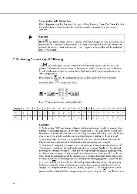
The key can be used to adapt the power of two heating circuits individually to the<br />
process. The controller has two heater outputs whose ratio to one another can be adjusted<br />
by selectively reducing the two output lines. At delivery, both heating outputs are set to<br />
100% output power.<br />
By pressing the key, the configured ratio in the table is initially shown. Use the<br />
numerical block to change this ratio.<br />
Fig. 27: Setting the heating circuit relationship<br />
Display 0 10 20 30 40 50 60 70 80 90 100 110 120 130 140 150 160 170 180 190 200<br />
A1<br />
0<br />
%<br />
10<br />
%<br />
20<br />
%<br />
30<br />
%<br />
40<br />
%<br />
A2 100 100 100 100 100 100 100 100 100 100 100 90<br />
%<br />
50<br />
%<br />
60<br />
%<br />
70<br />
%<br />
80<br />
%<br />
90<br />
%<br />
100 100 100 100 100 100 100 100 100 100 100<br />
Examples:<br />
1) At the setting "200", the furnace is heated only through output 1 (A1), for instance for a<br />
furnace for fusing applications, if only the ceiling heater is to be used and the side or floor<br />
heater is to be turned off. Note that when operating with reduced heating power, the furnace<br />
may no longer be able to reach the maximum temperature specified on the type plate!<br />
2) At setting "100", the furnace is operated with both heat outputs without reduction, for<br />
instance for an even temperature distribution when baking clay and ceramics.<br />
3) At setting "0", output 1, for instance, the ceiling heater in fusing furnaces, is turned off.<br />
The furnace is heated only through the heater attached to output 2 (A2), e.g. the side and<br />
floor (see the furnace description). Note that when operating with reduced heating power,<br />
the furnace may no longer be able to reach the maximum temperature specified on the type<br />
plate! Since the configuration of the output power is process-dependent, these settings can<br />
be saved directly in the heating program. First enter the heating program as described, and<br />
then press the key to specify the relationship between heating outputs. By saving the<br />
heating program, the entire programming including the configured output power can be<br />
assigned to a program memory (see also "Saving Programs"). The settings for the output<br />
power can also be controlled or changed at any time by pressing the key. If there is no<br />
80<br />
%<br />
70<br />
%<br />
60<br />
%<br />
50<br />
%<br />
40<br />
%<br />
30<br />
%<br />
20<br />
%<br />
10<br />
%<br />
0<br />
%