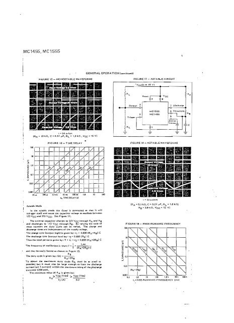
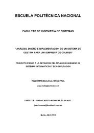
MC1455,MC1555 FIGURE 15 - MQNOSTA8LE WAVEFORMS IRA - 10 vn. c - 0.01 »F. RL - 1,0 f<strong>en</strong> ,vcc- is V] GENERAL OPERATION (continued) 1 1 OutDUt I I 1 Trloo«r FIGURE 17 - ASTABLE CIRCUIT *Vcc(5 to 15 V) 2 MC1555 MC1*55 6 Threino u¿ -f> 1 1 *~1 1- 1 T T 4=" 4=* •=• FIGURE 1G-TIMEDELAY FIGURÉIS- ASTABLE WAVEFORMS \/ 1/1 i/ izu x 1/1 i 1/1 i i 1/1 u i/rDnxf Trixí u M n 100MI 1.0 mi 10 rm IDO CID U) 10 100 Id.TIMEDEUYitl ln tfic asistí e nvxl* th.e tinw ii connected «o trut It will tcrrigow itíelf »nd caute the capacitor voltage lo oicil<strong>la</strong>te beuve<strong>en</strong> 1/3 VCC ind 3/3 Vcc. Seu F'^ure 17. The e.xternal capacitor chaf oca to 2/3 VQQ through RA and Rg •nd diichargei to 1/3 VQQ through Rg. 8y varying the ntka of tr^ev: feíinori ir>e duty cy<strong>de</strong> cwi be varied. The crwrge «nd rficwge lifyiM «re in<strong>de</strong>p<strong>en</strong><strong>de</strong>nt oí the lUppfy voltaoe. The ct»fgí tirrw (outpot highl ii giv<strong>en</strong> by: t] - O.B95(RA-Ra) C The diwíhargc time (output lowl by: 12 - 0.695 [Hgl C Thuithe total peíiod n giv-n by: T - IT i- t2 " Q.69S (RA+2RBÍ C 1 1-14 Tbe frequ<strong>en</strong>cy of oicil<strong>la</strong>tion ii tbcn: f - ~ - T lRA+2Rg! C •od frví^ be eawly found « ihown in Figure 19. TNr Outy cy<strong>de</strong> ii givvi by: DC To otxnn the rn»xinxim OUIY cy<strong>de</strong> RA nxJtt be u tn»ll 11 ponib*e; bol ¡i nxj« «lio be Iwge er>ough lo limit the i curroit (p-n 7 curr<strong>en</strong>t) withín ih* ir«xinxjm r«1ng of 1 tr.ni¡UíX (200 rnA). I7 (A) RB (RA -s.i kn.c- o.oi >JF. RL- 1.0 vn; RB-33kíl.Vcc- 15 V] FIGURE 19- FREE-HUNNING FREQU^NCY 0.1 1.D ID 100 1JJV ID I 1001 t. FREE-RUNNING FREQUENCY (Hr)
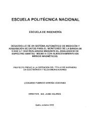
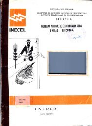
AWG ; N? . 0000 000 00 : o 1 ! 2 : s 1 4 í 5 6 7 89 10 11 12 13 14 : 15 16 17 18 19 20 21 22 23 24 25 26 27 23 29 30 31 32 1 33 34 35 36 37 38 39 40 ALAMBRES, CABLES Y AISLACIONES * TABLA 4 a. ALAMBRES DE COBRE (AMERICAN WIRE GAUGE} Diam. mm 11,7 10,4 9,28 8.P.5 7,35 6,53 5,81 5,18 4,63 4,12 3,66 3,25 2,90 2,59 2,30 2,05 1,83. 1,63 1,45 1,29 1,15 1,02 0,912 0,813 0',724 0,645 0,574 0,510 0,455 0,404 0,361 0,391 0,287 0,254 0,226 0,203 0,180 0,160 0,142 0,127 0,114 0,102 0,089 0,079 Seccíón"mm 107 85,1 67,6 53,4 42,4 33,4 26,6 21,0 16,8 13,3 10,5 8,30 6,62 5,34 4,16 3,30 2,64 2,09 1,65 1,31 1,04 0,816 0,6.65 0,504 0,412 0,326 0,254 0,204 0,163 0,128 0,102 0,080 0,0647 0,0506 0,0402 0,0324 0,0254 0,0201 0,0160 0,0126 0,0102 0,0081 0,0062 0,0049 Ohm por km a 20° C 0,16 0,203 0,255 0,322 0,406 0,513 0,646 0,817 1,03 1,30 1,63 2,06 2,60 3,27 4,14 5,20 6,56 8,29 10,4 13,2 16,6 20,9 26,4 33,0 42,8 52,4 66,0 83,4 105 132 167 211 265 334 421 532 671 846 1.065 1.345 1.696 2.140 2,700 3.400 i , , I metros kg por km , ^ por kg. 956 757 600 476 378 298 238 188 149 118 • 94,0 . 74,5 . 59,1 47,2 37,1 29,5 23,4 18,5 14,7 11,6 9,23 7,32 5,81 4,59 3,69 2,90 o 99 i|ao 1,43 1,14 0,91 0,72 0,57 0,45 0,36 0,286 0,227 0,177 0,142 0,113 0,091 0,072 0,054 0,045 1,05 1,32 1,67 2,10 2,64 3,46 - 4,20 5,32 6,71 ' 8,46 10,6 13,4 16,9 21,2 27,0 33,9 42,8 54,1 68,1 86,3 108 137 172 218 271 ' 345 436 556 700 877 1.100 1.390 1.750 2.220 2.780 3.500 4.400 5.650 7.050 8.840 11.000 13.900 18.500 22.200 41
- Page 1 and 2:
SISTEMA DIGITAL DE IIAMAM PARA ENFE
- Page 3 and 4:
CERTIFICACIÓN Certifico que el pre
- Page 5 and 6:
2.3.7. Diseño del Sistema de Trans
- Page 7 and 8:
P R C) L () G O La preservación de
- Page 9 and 10:
£A FATULO. I EL SISTEMA DE IL&3ADA
- Page 11 and 12:
- 3 - tes mecánicos que no present
- Page 13 and 14:
- 5 - manera podrian ser incompatib
- Page 15 and 16:
se Indica la llamada mediante un zu
- Page 17 and 18:
- 9 - ños debido a fallas -mecáni
- Page 19 and 20:
-li- ción central se realiza'por m
- Page 21 and 22:
- 13 - ción denominado "Control de
- Page 23 and 24:
- 15 - PISO 1 Figura 1.1. ESTACIÓN
- Page 25 and 26:
- 17 Ya que el sistema propuesto te
- Page 27 and 28:
SISTEMA DE PULSANTES TOMA DE l ' ;
- Page 29 and 30:
- 21 - una señal que posteriorment
- Page 31 and 32:
poníbles: - 23 - Por el teorema de
- Page 33 and 34:
- 25 - Vcc - V_ - Vp §1 E- (2.4) 4
- Page 35 and 36:
en su entrada un CEPO. - 27 - ,La p
- Page 37 and 38:
- 29 - c) Sus salidas deben retorna
- Page 39 and 40:
- 31 Para obtener la tabla de verda
- Page 41 and 42:
ed RC. En la figura 2.7 se. maestra
- Page 43 and 44:
- 35 - taje sobre el capacitor C2 .
- Page 45 and 46:
twout C3 . Leí 12 - 37 - Ra = 1639
- Page 47 and 48:
- 39 - fuente de corriente constant
- Page 49 and 50:
- 41 - LLOH, siendo ésta última l
- Page 51 and 52:
- 43 - la señal de aviso, pero no
- Page 53 and 54:
- - 45 - teriores mayores a 1000 PF
- Page 55 and 56:
- 47 - señal de control del genera
- Page 57 and 58:
fo1 ~ 1.44 • 2.56 1
- Page 59 and 60:
- 200 yA - 51 De acuerdo a las cara
- Page 61 and 62:
- 53 - El sistema de emergencia deb
- Page 63 and 64:
- 55 - ma para la señal de llamada
- Page 65 and 66:
- 57 - 10 mA VF = 1.2 V (ver caract
- Page 67 and 68:
'- 59 Para el cálculo de la resist
- Page 69 and 70:
61 - El encendido de estas- lámpar
- Page 71 and 72:
- 63 - como se dijo anteriormente l
- Page 73 and 74:
- 65 - 2.5. DISECO DE LA ESTACIÓN
- Page 75 and 76:
67 - En el diagrama de la figura 2.
- Page 77 and 78:
- 69 - Tomando en cuenta que la ent
- Page 79 and 80:
71 - condiciones señaladas por un
- Page 81 and 82:
- 73 - información en BCD a los
- Page 83 and 84:
- 75 • . tanto B1/R30 = CERO y LT
- Page 85 and 86:
00 01 11 10 T 77 - Figura 2.24. KE/
- Page 87 and 88:
- 79 X (No importa) con lo cual se
- Page 89 and 90:
- 81 - del decodificador es capaz d
- Page 91 and 92:
- 83 - CD = BI/RBO . SE + SE . FCP
- Page 93 and 94:
SECO - 85 - Figura 2.31. oCP del ci
- Page 95 and 96:
- 87 - Estando el control de lámpa
- Page 97 and 98:
- 89 -" Asumiendo que VOI ha conmut
- Page 99 and 100:
. Con la salida en bajo, "el voltaj
- Page 101 and 102:
Tdl = R7 6 In VH1 VL1 - 93 - (2.78)
- Page 103 and 104:
- 95 - (VOL, = 11.2 V ver caracter
- Page 105 and 106:
- 97 - que la del primero y además
- Page 107 and 108:
tra en los siguientes rangos: f, I2
- Page 109 and 110:
ecuación (2.62) V VEE R,84 - 101 -
- Page 111 and 112:
- 103 - do el potenciómetro está
- Page 113 and 114:
- 105 - te por debajo de 16 mA y co
- Page 115 and 116:
Rfl 7 ~~ Vcc '5 V 10 m¿ R87. R88 C
- Page 117 and 118:
- 109 - ó RQ(2) a CERO manteniendo
- Page 119 and 120:
- 111 - xado de retransmisión de l
- Page 121 and 122:
1.2 V - 113 La corriente de colecto
- Page 123 and 124:
- 115 - cribe madiante la ecuación
- Page 125 and 126:
LL-,0 7430 - 117 Figura 2.47. -^SIS
- Page 127 and 128:
. - 119 - 2.6. DISEflO DE 1A ESTACI
- Page 129 and 130:
- 121 - la compuerta está saturado
- Page 131 and 132:
- 123 La función CGE corresponde a
- Page 133 and 134:
De acuerdo con el sistema diseñado
- Page 135 and 136:
- 127 - Fuente de 12 V (V-r^O consu
- Page 137 and 138:
- 129 - Para la determinación dé
- Page 139 and 140:
c = P- se escoge Q 5 = 21000 p F/35
- Page 141 and 142:
- 133 - A continuación se diseñar
- Page 143 and 144:
j = 9.5 A •s - 135 - Se iniciará
- Page 145 and 146:
VCE4(máx) VCE4(máx) " 35 V - 137
- Page 147 and 148:
139 - = 4.5 A B, . = 20 por consigu
- Page 149 and 150:
D = 2.93 W Rscí = 0.140, - 141 Se
- Page 151 and 152: Consumo total: Vcc = 5 V ; Vcc « 4
- Page 153 and 154: 12 V - 1.2 V 15 - 145 - Se esc°Se
- Page 155 and 156: CAPITULO I. I. I CONSTRUCCIÓN EXPE
- Page 157 and 158: - 149 - filtro y mantener de este m
- Page 159 and 160: - 151 - 3.2.1. COMPROBACIÓN EXPERI
- Page 161 and 162: - 153 - la corriente AC que circula
- Page 163 and 164: - 155 - los optoacopladores, adicio
- Page 165 and 166: •N I fr A] VQ(74I6) [V] • - 157
- Page 167 and 168: ver en la foto de la figura 3.9. ES
- Page 169 and 170: nidos. - 161 - En el cuadro de la f
- Page 171 and 172: 3 circuitos integrados 7410 5 " - "
- Page 173 and 174: - 165 - 6 Conmutadores de. 2 polos
- Page 175 and 176: - 167 - Para obtener Tina nBJor dis
- Page 177 and 178: - 169 - CANTIDAD PRECIO UNIT. PRECI
- Page 179 and 180: - 171 - 4.1.4. COSTO DE 'lÁ ESTACI
- Page 181 and 182: - 173 MATERIAL . CANTIDAD PRECIO UN
- Page 183 and 184: - 175 - MATERIAL " " CANTIDAD PRECI
- Page 185 and 186: .- 177 - MATERIAL ' ' CANTIDAD PREC
- Page 187 and 188: 179 - para el hospital. Considerand
- Page 189 and 190: - 181 - . La Toma de Perilla que co
- Page 191 and 192: - 183 - res cuantos circuitos "Seri
- Page 193 and 194: - 185 - . te irá montada en un cir
- Page 195 and 196: SERIES 54/74 !-BUFFER AND INTERFACE
- Page 197 and 198: TYPES SN54122, SN74122. SN54123, SN
- Page 199 and 200: TYPES TIP120. TIP1Z1. TIP122 N-P-N
- Page 201: TYPE 2N3055 N-P-N SINGLE-DIFFUSED M
- Page 205 and 206: Serle* 1 (cont.) TRIAC OUTPUT, PANE
- Page 207 and 208: • LM2900/LM3900 Absoluta Máximum
- Page 209 and 210: 50 PKV Voln 50 IDO . . IDO 200 " 20
- Page 211 and 212: Atísolute Máximum Ratings InputVo
- Page 213 and 214: í_ Fflll i >li -f"^ < LLOH 5 BH U
- Page 215 and 216: ESCUELA PLANO DE MONTAJE D DEPERFLL
- Page 217 and 218: Lampara Incandescente Prof: Escala:
- Page 219 and 220: ! I ?. íil O GRAFÍA ' ' TEXAS INS