Descargar Tutorial de AutoCAD 2005 para 3D - Mundo Manuales
Descargar Tutorial de AutoCAD 2005 para 3D - Mundo Manuales
Descargar Tutorial de AutoCAD 2005 para 3D - Mundo Manuales

Create successful ePaper yourself
Turn your PDF publications into a flip-book with our unique Google optimized e-Paper software.
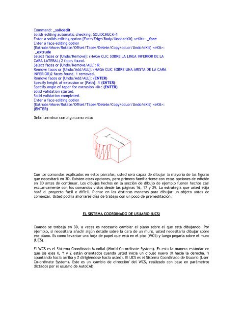
Command: _soli<strong>de</strong>ditSolids editing automatic checking: SOLIDCHECK=1Enter a solids editing option [Face/Edge/Body/Undo/eXit] : _faceEnter a face editing option[Extru<strong>de</strong>/Move/Rotate/Offset/Taper/Delete/Copy/coLor/Undo/eXit] :_extru<strong>de</strong>Select faces or [Undo/Remove]: (HAGA CLIC SOBRE LA LINEA INFERIOR DE LACARA LATERAL) 2 faces found.Select faces or [Undo/Remove/ALL]: RRemove faces or [Undo/Add/ALL]: (HAGA CLIC SOBRE UNA ARISTA DE LA CARAINFERIOR)2 faces found, 1 removed.Remove faces or [Undo/Add/ALL]: (ENTER)Specify height of extrusion or [Path]: 1 (ENTER)Specify angle of taper for extrusion : (ENTER)Solid validation started.Solid validation completed.Enter a face editing option[Extru<strong>de</strong>/Move/Rotate/Offset/Taper/Delete/Copy/coLor/Undo/eXit] :(ENTER)Debe terminar con algo como esto:Con los comandos explicados en estos párrafos, usted será capaz <strong>de</strong> dibujar la mayoría <strong>de</strong> las figurasque necesitará en <strong>3D</strong>. Existen otras opciones, pero primero familiarícese con estas opciones <strong>de</strong> ediciónen <strong>3D</strong> antes <strong>de</strong> continuar. Los dibujos hechos en la sección <strong>de</strong> dibujo <strong>de</strong> ejemplo fueron hechos casiexclusivamente con los comandos vistos <strong>de</strong>s<strong>de</strong> las páginas 16, 17 y 29. La estrategia que usted elijahará el proyecto fácil o difícil. Piense en las distintas maneras <strong>para</strong> dibujar un objeto antes <strong>de</strong>comenzar. Usted podría ahorrarse días <strong>de</strong> trabajo con un poco <strong>de</strong> premeditación.EL SISTEMA COORDINADO DE USUARIO (UCS)Cuando se trabaja en <strong>3D</strong>, a veces es necesario cambiar el plano sobre el que está dibujando. Porejemplo, si necesitara añadir algún <strong>de</strong>talle sobre la cara <strong>de</strong> un muro, usted necesitaría dibujar sobreese plano. Es como levantar una hoja <strong>de</strong> papel que está en el piso (WCS) y luego pegarla sobre el muro(UCS).El WCS es el Sistema Coordinado Mundial (World Co-ordinate System). Es esta la manera estándar enque los ejes X, Y y Z están orientados cuando usted inicia un dibujo nuevo (X hacia la <strong>de</strong>recha, Yapuntando hacia arriba y Z dirigiéndose hacia usted). El UCS es el Sistema Coordinado <strong>de</strong> Usuario (UserCo-ordinate System). Este es un 'cambio <strong>de</strong> dirección' <strong>de</strong>l WCS, realizado con base en parámetrosdictados por el usuario <strong>de</strong> <strong>AutoCAD</strong>.