GASPARDO Seminatrici SpA - Opico
GASPARDO Seminatrici SpA - Opico
GASPARDO Seminatrici SpA - Opico

Create successful ePaper yourself
Turn your PDF publications into a flip-book with our unique Google optimized e-Paper software.
48<br />
ENGLISH<br />
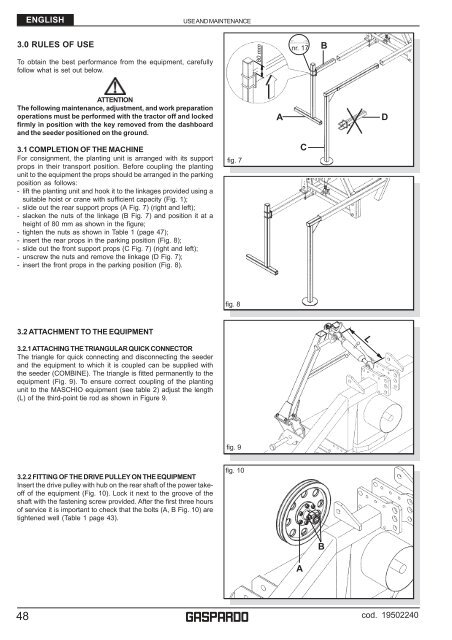
3.0 RULES OF USE<br />
To obtain the best performance from the equipment, carefully<br />
follow what is set out below.<br />
ATTENTION<br />
The following maintenance, adjustment, and work preparation<br />
operations must be performed with the tractor off and locked<br />
firmly in position with the key removed from the dashboard<br />
and the seeder positioned on the ground.<br />
3.1 COMPLETION OF THE MACHINE<br />
For consignment, the planting unit is arranged with its support<br />
props in their transport position. Before coupling the planting<br />
unit to the equipment the props should be arranged in the parking<br />
position as follows:<br />
- lift the planting unit and hook it to the linkages provided using a<br />
suitable hoist or crane with sufficient capacity (Fig. 1);<br />
- slide out the rear support props (A Fig. 7) (right and left);<br />
- slacken the nuts of the linkage (B Fig. 7) and position it at a<br />
height of 80 mm as shown in the figure;<br />
- tighten the nuts as shown in Table 1 (page 47);<br />
- insert the rear props in the parking position (Fig. 8);<br />
- slide out the front support props (C Fig. 7) (right and left);<br />
- unscrew the nuts and remove the linkage (D Fig. 7);<br />
- insert the front props in the parking position (Fig. 8).<br />
3.2 ATTACHMENT TO THE EQUIPMENT<br />
3.2.1 ATTACHING THE TRIANGULAR QUICK CONNECTOR<br />
The triangle for quick connecting and disconnecting the seeder<br />
and the equipment to which it is coupled can be supplied with<br />
the seeder (COMBINE). The triangle is fitted permanently to the<br />
equipment (Fig. 9). To ensure correct coupling of the planting<br />
unit to the MASCHIO equipment (see table 2) adjust the length<br />
(L) of the third-point tie rod as shown in Figure 9.<br />
3.2.2 FITTING OF THE DRIVE PULLEY ON THE EQUIPMENT<br />
Insert the drive pulley with hub on the rear shaft of the power takeoff<br />
of the equipment (Fig. 10). Lock it next to the groove of the<br />
shaft with the fastening screw provided. After the first three hours<br />
of service it is important to check that the bolts (A, B Fig. 10) are<br />
tightened well (Table 1 page 43).<br />
USE AND MAINTENANCE<br />
fig. 7<br />
fig. 8<br />
fig. 9<br />
fig. 10<br />
g<br />
80 mm<br />
A<br />
nr. 17<br />
A<br />
C<br />
B<br />
B<br />
L<br />
D<br />
cod. 19502240