GASPARDO Seminatrici SpA - Opico
GASPARDO Seminatrici SpA - Opico
GASPARDO Seminatrici SpA - Opico

Create successful ePaper yourself
Turn your PDF publications into a flip-book with our unique Google optimized e-Paper software.
56<br />
ENGLISH<br />
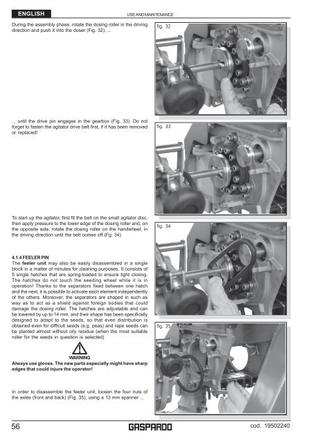
During the assembly phase, rotate the dosing roller in the driving<br />
direction and push it into the doser (Fig. 32), ...<br />
... until the drive pin engages in the gearbox (Fig. 33). Do not<br />
forget to fasten the agitator drive belt first, if it has been removed<br />
or replaced!<br />
To start up the agitator, first fit the belt on the small agitator disc,<br />
then apply pressure to the lower edge of the dosing roller and, on<br />
the opposite side, rotate the dosing roller on the handwheel, in<br />
the driving direction until the belt comes off (Fg. 34).<br />
4.1.4 FEELER PIN<br />
The feeler unit may also be easily disassembled in a single<br />
block in a matter of minutes for cleaning purposes. It consists of<br />
5 single hatches that are spring-loaded to ensure tight closing.<br />
The hatches do not touch the seeding wheel while it is in<br />
operation! Thanks to the separators fixed between one hatch<br />
and the next, it is possible to activate each element independently<br />
of the others. Moreover, the separators are shaped in such as<br />
way as to act as a shield against foreign bodies that could<br />
damage the dosing roller. The hatches are adjustable and can<br />
be lowered by up to 14 mm, and their shape has been specifically<br />
designed to adapt to the seeds, so that even distribution is<br />
obtained even for difficult seeds (e.g. peas) and rape seeds can<br />
be planted almost without oily residue (when the most suitable<br />
roller for the seeds in question is selected)<br />
WARNING<br />
Always use gloves. The new parts especially might have sharp<br />
edges that could injure the operator!<br />
In order to disassemble the feeler unit, loosen the four nuts of<br />
the axles (front and back) (Fig. 35), using a 13 mm spanner ...<br />
USE AND MAINTENANCE<br />
fig. 32<br />
fig. 33<br />
fig. 34<br />
fig. 35<br />
g<br />
cod. 19502240