GASPARDO Seminatrici SpA - Opico
GASPARDO Seminatrici SpA - Opico
GASPARDO Seminatrici SpA - Opico

You also want an ePaper? Increase the reach of your titles
YUMPU automatically turns print PDFs into web optimized ePapers that Google loves.
52<br />
ENGLISH<br />
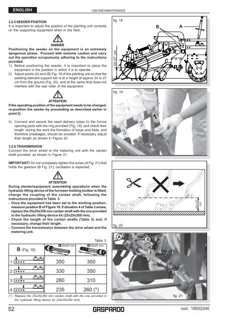
3.2.5 SEEDER POSITION<br />
It is important to adjust the position of the planting unit correctly<br />
on the supporting equipment when in the field.<br />
DANGER<br />
Positioning the seeder on the equipment is an extremely<br />
dangerous phase. Proceed with extreme caution and carry<br />
out the operation scrupulously adhering to the instructions<br />
provided.<br />
1) Before positioning the seeder, it is important to place the<br />
equipment in the position in which it is to operate.<br />
2) Adjust points (A) and (B) Fig. 18 of the planting unit so that the<br />
seeding element support bar is at a height of approx 24 to 27<br />
cm from the ground (Fig. 20), and at the same time does not<br />
interfere with the rear roller of the equipment<br />
ATTENTION<br />
If the operating position of the equipment needs to be changed,<br />
re-position the seeder by proceeding as described earlier in<br />
point 2).<br />
3) Connect and secure the seed delivery tubes to the furrow<br />
opening parts with the ring provided (Fig. 19), and check their<br />
length: during the work the formation of loops and folds, and<br />
therefore breakages, should be avoided. If necessary adjust<br />
their length as shown in Figure 20.<br />
3.2.6 TRANSMISSION<br />
Connect the drive wheel to the metering unit with the cardan<br />
shaft provided, as shown in Figure 21.<br />
IMPORTANT! Do not completely tighten the screw (A Fig. 21) that<br />
holds the gearbox (B Fig. 21); oscillation is expected.<br />
ATTENTION<br />
During planter/equipment assembling operations when the<br />
hydraulic lifting device of the furrower-holding toolbar is fitted,<br />
change the coupling of the cardan shaft, following the<br />
instructions provided in Table 3:<br />
- Once the equipment has been set to the working position,<br />
measure position B of Figure 18. If situation 4 of Table 3 arises,<br />
replace the 25x25x350 mm cardan shaft with the one provided<br />
in the hydraulic lifting device kit (25x25x260 mm).<br />
- Check the length of the cardan shafts (Table 3) and, if<br />
necessary, change their length.<br />
- Connect the transmission between the drive wheel and the<br />
metering unit.<br />
1<br />
2<br />
3<br />
4<br />
B (Fig. 18)<br />
350<br />
330<br />
280<br />
235<br />
Table 3<br />
20x20 mm 25x25 mm<br />
USE AND MAINTENANCE<br />
350<br />
350<br />
310<br />
260 (*)<br />
(*) Replace the 25x25x350 mm cardan shaft with the one provided in<br />
the hydraulic lifting device kit (25x25x260 mm).<br />
fig. 18<br />
24÷27 cm<br />
fig. 19<br />
fig. 20<br />
g<br />
B<br />
12345678901234567890123456789012123456789012345<br />
12345678901234567890123456789012123456789012345<br />
12345678901234567890123456789012123456789012345<br />
A<br />
B<br />
A<br />
fig. 21<br />
24÷27<br />
cm<br />
cod. 19502240