
Create successful ePaper yourself
Turn your PDF publications into a flip-book with our unique Google optimized e-Paper software.
<strong>termosanitaria</strong> <strong>by</strong> <strong>Luxor</strong><br />
Technical data<br />
Max working pressure 10 bar<br />
Max working temperature 120 °C<br />
Technical data with thermostatic heads art.TE<br />
Fluid temperature 0 °C ÷ 100 °C<br />
Cabinet working temperature 0 °C ÷ 60 °C<br />
Maximum relative humidity 80%<br />
Stocking temperature -25 °C ÷ 60 °C<br />
Technical data with flow meters<br />
regulators art. TM 4010<br />
Maximum working pressure 6 bar<br />
Maximum working temperature 80 °C<br />
Construction characteristics<br />
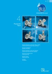
The pre-assembled manifolds are produced with the following side<br />
interaxes:<br />
• 40 mm – G 3/4<br />
• 50 mm – G 1”<br />
• 50 mm – G 1” 1/4<br />
All manifolds are produced with yellow or nickel plated finishing.<br />
The brass bodies of the manifolds are produced in brass<br />
CW 617N UNI-EN 12165-98 in compliance to the recent<br />
regulation defining the limit of lead use.<br />
The threading on the main connections are in compliance to<br />
ISO 228 regulation.<br />
The secondary circuits can be connected through fittings with threading<br />
M24X19 and G 3/4 Eurokonus. All components of the manifold are<br />
assembled and fixed to avoid possible unscrewing in case of<br />
disassembling of parts.<br />
All the fittings and manifolds accessories (drain valves, terminal caps,<br />
etc) are equipped with a soft tightening o-ring and do not require any<br />
type of sealing element (such as hemp, PTFE etc.).<br />
The tightening device on the stem of the manifolds with pre-assembled<br />
valves set for the thermoelectric regulation, can be inspected and<br />
replaced even when the system is operating.<br />
The piston rod is in stainless steel AISI 316 with tightness ensured <strong>by</strong> two<br />
peroxide EPDM o-rings.<br />
The protection cap, whereas the use is required, is necessary first of all<br />
to protect the threading and occasionally to intercept the fluid derivation.<br />
The regulating and balancing manifolds (lockshield type) are equipped<br />
with a double micrometric regulation with memory of position, in case<br />
of temporary shut down, and can be assembled both on the circuit inlet<br />
or outlet.<br />
The regulating and balancing manifolds, with regulators and meter<br />
TM 4010, allow an immediate inspection of the system assessment<br />
<strong>by</strong> reading the flow. The regulation can be stopped through a stop<br />
lid. The cup and the spring can be assembled and cleaned while the<br />
system is operating.<br />
For a correct functioning of the system, we suggest to install between<br />
the inlet and the outlet an overpressure valve.<br />
To avoid excess of noise of the system do not use thermostatic valves<br />
with Δp higher than 0.2-0.25 bar.<br />
Технические данные<br />
Максимальное рабочее давление: 10 бар.<br />
Максимальная рабочая температура: 120°С<br />
CD<br />
5<br />
Условия эксплуатации коллекторов в сборе с<br />
термоэлектрическими головками арт. ТЕ<br />
(см. Технический каталог №2, стр. 55_61)<br />
Рабочая температура: 0 °С ÷ 100 °С<br />
Рабочая температура помещения: 0 °С ÷ 60 °С<br />
Максимальная относительная влажность (без конденсации): 80%<br />
Температура хранения: -25 °С ÷ 60 °С<br />
Условия эксплуатации коллекторов в сборе со<br />
встроенными регуляторами-измерителями<br />
расхода воды арт. ТМ 4010<br />
Максимальное рабочее давление: 6 бар.<br />
Максимальная рабочая температура: 80 °С<br />
Технические характеристики конструкции<br />
Распределительные коллекторы произведены с межцентровыми<br />
расстояниями между выходами от<br />
• 40 мм – G 3/4<br />
• 50 мм - G1”<br />
• 50 мм - G 1”1/4<br />
Все коллекторы произведены с никелевым покрытием или в<br />
«желтом» цвете.<br />
Штампованные корпуса коллекторов изготовлены из латуни<br />
CW 617 UNI–EN 12165-98.<br />
Выходы коллекторов выполнены по нормативам ISO 228<br />
Cоединения с боковыми отводами осуществляется с помощью<br />
фитингов с резьбой М24х19 и G 3/4 Еврокону. Компоненты<br />
коллектора устанавливаются одинаково и фиксируются. Все<br />
фитинги и принадлежности к коллекторам (вентили выпускные<br />
колпачки.и т.д.) снабжены мягкими прокладками o-ring нет<br />
необходимости в дополнительных прокладках типа пакли,и<br />
т.д.Соединение штока. Коллекторов со встроенными вентилями<br />
предполагают электротермическую регулировку.<br />
И могут контролироваться и заменяться также в работающей<br />
системе.<br />
Управляющий маховичок выполнен из нержавеющего металла<br />
AISI 316 c двумя уплотнительными прокладками 0-ring из EPDM<br />
для герметичности соединения.<br />
Защитный колпачок , предусмотрен прежде всего для защиты<br />
резьбы от повреждений.<br />
Коллекторы регулировки (типа лапанов) с регуляторами и<br />
измерениями напора TM 4010 Дают возможность моментальной<br />
проверки напора.Регулировка может быть блокирована путем<br />
использования блокирующего колпачка. Стакан и измерительную<br />
пружину могут быть разобраны и промыты также в работающем<br />
режиме системы.<br />
Для правильного установления рабочего режима системы<br />
рекомендуется всегда установить вентиль между подачей и<br />
обраткой.<br />
Во избежание повышенного шума системы рекомендуется<br />
избегать применения вентилей С характеристиками<br />
превышающими 0,2 – 0,25 бар.<br />
119