
Create successful ePaper yourself
Turn your PDF publications into a flip-book with our unique Google optimized e-Paper software.
BDAL 6906_116306906 05.08.13 17:32 Seite 43<br />
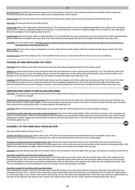
Protective hood: Assemble the individual components of the protective hood first. Then slide the protective hood holder with the guide into<br />
the aluminium profile and tighten the two Allen screws using the Allen wrench (Fig. 6).<br />
Switch clamp: Knot one end of the cord in the hole of the switch clamp and the other end with the protective hood holder (Fig. 7).<br />
Push stick: Put the push stick on the holder (Fig. 8).<br />
Angle guide: Mount the angle guide as illustrated (Fig. 9). The aluminium rail may have to be adjusted depending on the height of the workpiece.<br />
Vertical with a minimum workpiece height of 15 mm (Fig. 9.1), horizontal with a maximum workpiece height of 15 mm (Fig. 9.1). The angle guide<br />
directs the workpiece into the guide groove (Fig. 9.3).<br />
Parallel guide: Mount the guide holder as illustrated (Fig. 10.1). Assemble the two screws and square nuts only loosely (10.2). Slide in the aluminium<br />
guide as illustrated and tighten the screws (Fig. 10.3). Then slide the parallel guide into the slot and tighten the knurled screw (Fig. 10.4).<br />
CAUTION: Lock the machine plate: The Allen wrench is used to lock the machine plate and must be inserted in the table in the "lock" position as<br />
illustrated before starting work (Fig. 11).<br />
Spacer rings: The two spacer rings are designed to increase safety during routing. Always select the smallest possible spacer ring for the cutter<br />
being used (Fig. 12).<br />
Clamping claws: Insert the clamping claws in the predrilled holes and use in conjunction with the vice to secure your workpieces.<br />
t<br />
FOLDING UP AND UNFOLDING THE TABLE<br />
CAUTION: Before folding up the table, always disconnect the mains plug and appliance inlet from the safety switch!<br />
Folding up: Slacken both knurled screws enough to allow the two locking levers to be retracted and turned (Fig. 14.1). Then fold the table in the<br />
direction of the arrow. For your own safety, always rest your foot against one of the cushion feet as illustrated to ensure that the table cannot<br />
slip (Fig. 14.2). The wheels on the cushion feet are used to transport the table more easily (Fig. 14.3).<br />
Unfolding: Hold the table securely with both hands and rest your foot against one of the cushion feet as illustrated (Fig. 15.1). Now tilt the table<br />
in the direction of the arrows in a single movement until it has unfolded completely (Fig. 15.2). Then push the front edge of the table down<br />
with one hand until the top section engages in position. Insert both locking levers into the holes and tighten both knurled screws (Fig. 15.3).<br />
PREPARATIONS PRIOR TO INSTALLING MACHINES<br />
CAUTION: The procedure for opening and closing the machine plate before starting work is described here and must be performed every time<br />
a machine is changed!<br />
Opening the machine plate to install a machine: Remove the Allen wrench from the safety lock. Swivel both plastic levers upwards, hold the two<br />
levers and raise the machine plate slightly. Lift the machine plate in the direction of the arrow until it is vertical and slide forwards up to the guide.<br />
Then lay down the machine plate until it is resting safely on the table (Fig. 16).<br />
CAUTION: When working with the machine plate, do not reach under the machine plate with your fingers (danger of injury).<br />
Closing the machine plate after successful machine installation: Raise the machine plate slightly. Then push all the way back to the rear guide and<br />
raise to a vertical position. Hold the machine plate by the two plastic levers and tilt the machine plate in the direction of the arrow until it reaches<br />
engagement position. Engage the machine plate from above and close both plastic levers. Insert the Allen key back into the safety socket to lock<br />
the machine plate (Fig. 17).<br />
ASSEMBLY OF THE HAND-HELD CIRCULAR SAW<br />
Open the machine plate as shown in Fig. 16.<br />
Suitable hand-held circular saws: Please refer to Fig. 18 for the maximum dimensions permitted dimensions of hand-held circular saws.<br />
Always use circular hand saws with a riving knife, max. 200 mm saw blade diameter and max. 70 mm cutting depth.<br />
Assembly and alignment of the hand-held circular saw: Retract the protective pendulum hood on the hand-held circular saw and position the<br />
machine centrally over the saw gap. Release the cutting depth lock on the circular saw and set the machine to the maximum cutting depth (Fig. 18.2).<br />
Tighten the cutting depth lock again. Align the blade on the circular saw centrally and parallel to the saw gap.<br />
CAUTION: Check the distance between the foremost tooth on the saw blade to the front edge of the saw gap. This distance must be less than 20 mm.<br />
Assembly example for machines with smaller base plates.<br />
After aligning the machine, attach the two side stops so that their surfaces are in full contact with the machine’s base plate. Then attach the two<br />
clamping claws (Fig. 18.3). Secure one side of the base plate. Install the angle bracket with two side stops first. Make sure they are in full contact<br />
with the base plate. In the same way, install an angle bracket with two side stops on the opposite side. Attach the two clamping claws (Fig. 18.4).<br />
The two clamping claws must be installed as close to the longer side of the base plate as possible.<br />
Assembly example for machines with larger base plates.<br />
After aligning the machine, attach the two side stops so that their surfaces are in full contact with the machine’s base plate. Then attach the two<br />
clamping claws (Fig. 18.5 c). Install the two side stops as close to the longer side of the base plate as possible (Fig. 18.5 d). Attach the angle bracket<br />
to a side stop using a screw, washer, lock washer and nut (Fig. 18.5 b). Then attach the clamping claws. In the same way, attach an angle bracket to a<br />
side stop on the opposite side using a screw, washer, lock washer and nut (Fig. 18.5 b). Finally, attach the clamping claws (Fig. 18.5 a).<br />
43