- Page 1 and 2: ANLEITUNG FÜR EINBAU, BEDIENUNG UN
- Page 3: 1. SicherheitshinweiseVerantwortung
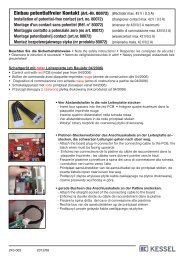
- Page 7 and 8: 3. Montage / Elektroanschluss3.2 Ka
- Page 9 and 10: 3. Montage / Elektroanschluss3.4 An
- Page 11 and 12: 3. Montage / Elektroanschluss3.5 Ex
- Page 13 and 14: 4. Betrieb4.1 InbetriebnahmeDen Bat
- Page 15 and 16: 4. Betrieb4.4.2 Kurzzeitig erhöhte
- Page 17 and 18: 5. FehlererkennungMit dem KESSEL-Sc
- Page 19 and 20: 5. FehlererkennungNetzausfall:Mono
- Page 21 and 22: 7. Technische DatenSchaltgerät KES
- Page 23 and 24: 9. Gewährleistung1. Ist eine Liefe
- Page 25: 11. Übergabeprotokoll für den Bet
- Page 28 and 29: ❑ Rückstauverschlüsse❑ Hebean
- Page 30 and 31: 1. Safety InstructionsThe safety in
- Page 32 and 33: Table of contents1. Safety Instruct
- Page 36 and 37: 3. Installation / Electrical Connec
- Page 38 and 39: 3. Installation / Electrical Connec
- Page 40 and 41: 4. Operationdbaefgihcjk la) Control
- Page 42 and 43: 4. Operation4.3 Displays / Operatin
- Page 44 and 45: 4. Operationwill also turn off. The
- Page 46 and 47: 5. Trouble ShootingMono Duo Cause R
- Page 48 and 49: 6. Additional functions6.1 Automati
- Page 50 and 51: 8. Inspection and Maintenance8.1 In
- Page 52 and 53: 10. Declaration of conformity52
- Page 55 and 56: 12. Handover Certificate for instal
- Page 57 and 58: Directives pour la pose, le service
- Page 59 and 60: 1. Consignes de sécuritéres, il d
- Page 61 and 62: 2. GénéralitésLors de tous les t
- Page 63 and 64: 3.2 Raccord de câble3. Montage / R
- Page 65 and 66: 3.4 Schéma de branchement3. Montag
- Page 67 and 68: 3. Montage / Raccordement électriq
- Page 69 and 70: 4. Exploitation4.1 Mise en serviceI
- Page 71 and 72: 4. Exploitation4.4.2 Augmentation d
- Page 73 and 74: 5. Détection de pannesAvec le boî
- Page 75 and 76: 5. Détection de pannesPanne de ré
- Page 77: 7. Données techniquesBoîtier de c
- Page 80 and 81: 10. Declaration de conformité80
- Page 83: 12. Procès verbal de remise pour l
- Page 86 and 87:
1. Avvertenze sulla sicurezzaLe avv
- Page 88 and 89:
Indice1. Avvertenze sulla sicurezza
- Page 90 and 91:
3. Montaggio / allacciamento elettr
- Page 92 and 93:
3. Montaggio / allacciamento elettr
- Page 94 and 95:
3. Montaggio / allacciamento elettr
- Page 96 and 97:
4. Funzionamentodbaefgihcjk la) Sca
- Page 98 and 99:
4. Funzionamento4.3 Descrizioni deg
- Page 100 and 101:
4. Funzionamento2 secondi viene acc
- Page 102 and 103:
5. Riconoscimento erroriMono Duo Ca
- Page 104 and 105:
6. Funzioni addizionali6.1 Test aut
- Page 106 and 107:
8. Ispezione e manutenzione8.1 Ispe
- Page 108 and 109:
10. Dichiarazione di conformità108
- Page 110 and 111:
110
- Page 112 and 113:
❑ Protezione antiriflusso❑ Staz
- Page 114 and 115:
1. VeiligheidsinstructiesDe in deze
- Page 116 and 117:
Inhoudsopgave1. Veiligheidsinstruct
- Page 118 and 119:
3. Montage / Elektrische aansluitin
- Page 120 and 121:
3.3 Elektrische aansluiting3. Monta
- Page 122 and 123:
3. Montage / Elektrische aansluitin
- Page 124 and 125:
4. Werkingdbaefgihcjk la) Kast scha
- Page 126 and 127:
4. Werking4.3 Beschrijving van indi
- Page 128 and 129:
4. WerkingBeide pompen lopen met el
- Page 130 and 131:
5. FoutherkenningMono Duo Oorzaak U
- Page 132 and 133:
6. Extra functies6.1 Automatische p
- Page 134 and 135:
8. Inspectie en onderhoud8.1 Inspec
- Page 136 and 137:
10. Conformiteitsverklaring136
- Page 138 and 139:
138
- Page 140 and 141:
❑ Terugstroombeveiligingen❑ Opv
- Page 142 and 143:
1. Wskazówki dotyczące bezpiecze
- Page 144 and 145:
Spis treści1. Wskazówki dotycząc
- Page 146 and 147:
3. Montaż/podłączenie do instala
- Page 148 and 149:
3. Montaż/podłączenie do instala
- Page 150 and 151:
3. Montaż/podłączenie do instala
- Page 152 and 153:
4. Eksploatacjadbaefhgicklma) Obudo
- Page 154 and 155:
4. Eksploatacja4.3 opis elementów
- Page 156 and 157:
4. EksploatacjaPo czterech sekundac
- Page 158 and 159:
5. rozpoznawanie błędówMono Duo
- Page 160 and 161:
6. Funkcje dodatkowe6.1 automatyczn
- Page 162 and 163:
8. Inspekcja i konserwacja8.1 Inspe
- Page 164 and 165:
10. Deklaracja zgodności164
- Page 166 and 167:
166
- Page 168:
❑ Zawory zwrotne❑ Przepompownie