Create successful ePaper yourself
Turn your PDF publications into a flip-book with our unique Google optimized e-Paper software.
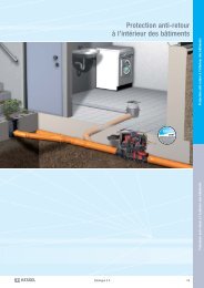
3. Installation / Electrical Connections3.5 Remote alarm signalThe remote alarm signal (Article Number2<strong>01</strong>62) is available as an accessory. Thisalarm is connected to the control unit andthen normally installed in a separate room sothat the alarm signal can be heard more easily.3.6 Potential free contactAlso available as an accessory is a potentialfree contact (Article Number 80072)which can also be installed inside the controlunit. The potential free contact is usedto transfer malfunction or alarm signals toa Building Management System (BMS).3.7 Shortening cablesCautionin the case that any cables are shortenedthe connection jack should look as shownin Illustration 12.3.8 Extending cablesIll.12In the case that more than the supplied 5meters of cable is required, 10 meter extensionsare available. The 10 meter extensionfor the optical sensor is ArticleNumber 80889, for the motor Article Number80890 and for the pump Article Number80891.3.9 Connection of air hose /pressure switchCautionthe air pressure hose should be installedwith a continuous upward slope from thepumping system up to the control unit.The hose should not be looped, coiled orkinked and should have no low spots ordips. Insert the air hose into the controlunit in the proper location and secure thehose with the supplied finger nut. Thehose can be easily shortened by simplycutting it to the desired length. Air pressurehoses over 10 meters in length mustbe accompanied by a small compressorpump to assure that the air pressure remainsadequate. The maximum totallength of the air pressure hose is not to exceed30 meters.Notice:The VDE <strong>01</strong>00, VDE <strong>01</strong>107, the IEC and alllocal and national electrical safety regulationsshould be followed. The control unitis not to be installed in an area at risk ofexplosion. The 230V / 50 Hz power connectionis to be secured with a 16A (‘C’type) fuse with 30 mA FI protective switch.When all the electrical work has beencompleted the control unit cover shouldbe closed and secured with the screws.39