LeStrade luglio 2020
SPECIALE - L’innovazione italiana che spicca nel mondo PONTI - Progetto di ripristino di impalcati in acciaio MATERIALI - Il lavoro di squadra tra emulsioni e bitumi
SPECIALE - L’innovazione italiana che spicca nel mondo
PONTI - Progetto di ripristino di impalcati in acciaio
MATERIALI - Il lavoro di squadra tra emulsioni e bitumi
- No tags were found...

Create successful ePaper yourself
Turn your PDF publications into a flip-book with our unique Google optimized e-Paper software.
52<br />
53<br />
LS<br />
7<br />
8<br />
9<br />
Made in Italy<br />
cando forze esterne a supporto del materiale collassato, di<br />
un importo pari al peso di quest’ultimo. Il carico verticale<br />
esterno, pari a circa 300 ton, è stato applicato mediante<br />
due martinetti posizionati sulla trave a sbalzo dei piloni<br />
a sostegno del tampone , contrastati alla base da un contrappeso<br />
di massa adeguata.<br />
I piloni sono stati precedentemente rinforzati per garantire<br />
maggiore sicurezza a tutta l’operazione.<br />
Una volta completati i test funzionali di sicurezza, sono iniziate<br />
le fasi operative di demolizione. Sul lato Ovest, per<br />
lo smantellamento dei piloni e i relativi tamponi, è stata<br />
progettata una struttura in metallo di travi a sbalzo “Fagioli<br />
cantilever beam”, appoggiato direttamente sui piloni.<br />
Il sistema di sollevamento, posizionato all’estremità della<br />
sezione del ponte a sbalzo, ha sollevato gradualmente<br />
il tampone, per consentire il taglio del supporto su cui il<br />
manto stradale era stato posizionato in fase di costruzione<br />
e l’abbassamento dello stesso a terra. Il posizionamento<br />
dei martinetti in posizione opposta a quelli di sollevamento<br />
ha garantito la stabilità durante l’operazione. Il sistema<br />
di “cantilever beam” è stato progettato in modo tale da distribuire<br />
i carichi sui piloni in modo isostatico e uniforme,<br />
in grado di trasferire perfettamente il carico di 250 ton di<br />
ciascuno dei due martinetti sulle tre sezioni che componevano<br />
i piloni. Il carico trasferito su ciascuna struttura in<br />
cemento armato, è stato applicato "per supporto", cioè<br />
per contatto dal basso, e non "per trazione. Questo tipo di<br />
metodologia ha richiesto di praticare alcuni fori (eseguiti<br />
con carotatrici) sul cemento armato con lo scopo di aumentare<br />
la sicurezza.<br />
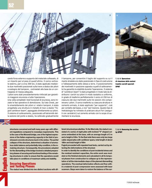
7, 8, 9. Operazione<br />
di rimozione delle sezioni<br />
tramite carrelli speciali<br />
SPMT<br />
Smontaggio piloni<br />
sul lato Ovest<br />
Una volta rimossi i tamponi del lato Ovest, il lavoro è continuato<br />
con lo smontaggio dei piloni. Questa attività è stata<br />
effettuata inizialmente con dei tagli longitudinali nella struttura<br />
in cemento, lunghi circa 36 m e con uno spessore fino<br />
a 3 m. L’intera struttura in cls è stata tagliata in 3 blocchi di<br />
grandi dimensioni con un peso che fosse adatto al sollevamento<br />
e alla rimozione mediante due gru cingolate Fagioli<br />
Demag CC-2800, in configurazione SSL, con braccio 78 m,<br />
Superlift 300 ton a 13m. A causa della forma dei piloni le<br />
gru sono state utilizzate come sostegno delle sezioni, durante<br />
il taglio. I fori ottenuti con il sistema di “carotaggio”,<br />
come già accennato precedentemente, hanno aumentato il<br />
livello di sicurezza e facilitato le operazioni durante le delicate<br />
e chirurgiche azioni di smontaggio. Tutti i blocchi ottenuti<br />
dal sezionamento dei piloni, una volta a livello del suolo,<br />
sono stati rimossi per mezzo dei carrelli Fagioli SPMT.<br />
Rimozione tampone 11<br />
sul lato Est<br />
Per quanto riguarda i due piloni sul lato Est che si sono conservati<br />
al crollo, essi erano molto più alti e più complessi da<br />
gestire rispetto ai piloni del lato Ovest poiché fissati con grandi<br />
travi a sbalzo. Per poter effettuare lo smantellamento del<br />
tampone 11, compreso appunto tra i piloni 10 e 11, Fagioli<br />
ha eretto tre coppie di torri di sollevamento, due per il pilone<br />
10 e una per il pilone 11, ciascuna alta 50 m, posizionate<br />
su fondamenta di cemento appositamente realizzate. Le<br />
torri di sollevamento avevano la funzione di sostenere tem-<br />
English Version<br />
structures conceived and built many years ago with different<br />
regulations compared to nowadays requirements. This<br />
is the case of the Morandi bridge, one of the highest expressions<br />
of the Italian engineering capacity in the field of prestressed<br />
concrete structures back in the sixties. The partial<br />
collapse of the structure, determined a situation of anomalous<br />
static balance and potentially risky condition, in the remaining<br />
structure. Consequently, the procedures adopted<br />
for the dismantling of the bridge involved a detailed preparatory<br />
phases of securing and functional testing of the remaining<br />
structures in order to ensure that the operations would<br />
take place in conditions of maximum safety and stability.<br />
Securing Operations<br />
and Testing Phases<br />
The viaduct was divided into two distinct sections with different<br />
structural peculiarities. To the West side, the viaduct consisted<br />
of a series of eight piles with inclined “V” shaped columns<br />
embedded at the base, with an average length of 3 m<br />
and a height of 45m. To the East side there were only two large<br />
cable-stayed piles with cantilever spans, total length of about<br />
180m and total height of 90m<br />
Fagioli proceeded with repeated load tests, carried out by detecting<br />
the deformations of the structure<br />
In order to identify the conditions of post-incidental stress and<br />
the residual resistant capacities, the entire work was modeled<br />
on the finished elements and calculated in all its temporal<br />
phases from construction to collapse up to the representation<br />
of all the intermediate steps of the planned dismantling<br />
operations. The eventual deformation effects and flow within<br />
a material of post-compression were assessed with laser<br />
scanners. Steps were taken to restore the balance of the sur-<br />
7, 8, 9. Removing the section<br />
by SPMT<br />
viving structures which resulted to have highly asymmetrical<br />
loads due to the lack of the collapsed structural elements.<br />
This is the case of pile 8 which, due to the loss of the Berger<br />
beam on the Eastern side, was in a strong unbalanced condition.<br />
The re-balancing operation was performed by applying<br />
external forces at the support of the collapsed pad, of an<br />
amount equal to the weight of the latter. The external vertical<br />
load, equal to about 300 tons, was applied by means<br />
of two cable recovery jacks positioned onto the cantilever<br />
beam of the pile, contrasted at the base by a counterweight<br />
of adequate mass. The piles were previously reinforced in order<br />
to guarantee more safety. Once the safety and functional<br />
tests were completed, the real demolition phases began. To<br />
the West side, the eight piles and the related Berger beams<br />
were dismantled in pieces. For the dismantling of the Berger<br />
beams, supported by the V shaped piles, a metal structural<br />
work system was designed “Fagioli cantilever beam system”,<br />
resting onto the piles. The lifting system, positioned at<br />
the end of the cantilever bridge section, raised it gradually,<br />
in order to allow the cutting of the support onto which it was<br />
placed and lowering it to the ground. The positioning of strand<br />
jacks opposite to the lifting one, guaranteed stability. The support<br />
system of the “Fagioli cantilever beam system” was designed<br />
to distribute the loads onto the pile in an isostatic and<br />
uniform manner, able to perfectly transfer the 250 ton load of<br />
each of the 2 strand jacks onto the three sections of the pile.<br />
The load transferred to each concrete structure, was applied<br />
“by support”, that is by contact from below, and not “by traction”.<br />
This kind of methodology required to do some holes<br />
(executed with core drilling machines) and avoiding plastering<br />
elements of carpentry onto the reinforced concrete. This<br />
action increased safety on site.<br />
7/<strong>2020</strong> leStrade<br />
7/<strong>2020</strong>