DW701 DW707 - Service - DeWalt
DW701 DW707 - Service - DeWalt
DW701 DW707 - Service - DeWalt

Create successful ePaper yourself
Turn your PDF publications into a flip-book with our unique Google optimized e-Paper software.
Assembly<br />
Prior to assembly always unplug the tool.<br />
The motor and guards are already assembled onto the base.<br />
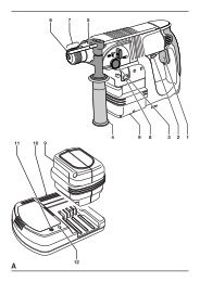
DE7777, option - dust extraction (fig. B)<br />
The nozzle (16) of the upper fixed blade guard is fitted in the factory.<br />
• Insert the middle dust extraction nozzle (34) as shown.<br />
• Secure the lower dust extraction nozzle (35) using the screws (36).<br />
• Fit the hoses (37) to the nozzles; the longer hose to nozzle (16).<br />
• Connect the hoses to the 3-way connector (38).<br />
• Whenever possible, connect a dust extraction device designed in<br />
accordance with the relevant regulations regarding dust emission.<br />
Fitting the fence insert (fig. A2 & C)<br />
Always use the mitre insert for all cuts!<br />
• Push the saw head (24) down to pull out the lock down button (22) and<br />
raise the saw head (fig. A2).<br />
• Insert the screws (40) and washers (41) into the holes (39) as shown to<br />
mount the fence insert (fig. C).<br />
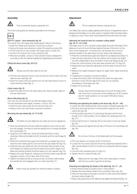
Cable clamp (fig. D)<br />
• Insert the cable (42) into the cable clamp (43). Allow enough cable for<br />
the saw head travel.<br />
Bench Mounting (fig. E)<br />
Your saw can be mounted on any flat and stable surface.<br />
The recommended work height, however, is 700 to 750 mm.<br />
• Insert the two coach bolts (45) into the two holes (21).<br />
• Always mount your saw firmly to prevent movement.<br />
Mounting the saw blade (fig. A1, F1 & F2)<br />
The teeth of a new blade are very sharp and can be dangerous.<br />
• Press the spindle lock (44) and rotate the blade by hand until you feel<br />
the lock engage. Continue to hold the spindle lock in to keep the blade<br />
from turning (fig. F1).<br />
• Using the 6 mm Allen key, loosen the blade bolt (6) by turning<br />
clockwise. Remove the blade bolt (6), its washer and the outer flange (5)<br />
(fig. A1).<br />
• Press the combined lower guard and head lock up release lever (2) to<br />
raise the lower blade guard (7) and remove the saw blade (45) (fig. F2).<br />
• Install the new saw blade (45) onto the shoulder (46) provided on the<br />
inner flange (47) making sure that the teeth at the bottom edge of the<br />
blade are pointing towards the fence (away from the operator) (fig. F2).<br />
• Replace the outer flange (5), making sure that the location lugs (48) are<br />
engaged correctly, one on each side of the motor.<br />
• Tighten the blade bolt (6) by turning counter-clockwise while holding<br />
the spindle lock (44) engaged with your other hand (fig. F1).<br />
Never press the spindle lock while the blade is rotating.<br />
Adjustment<br />
Prior to adjustment always unplug the tool.<br />
ENGLISH<br />
Your Mitre Saw was accurately adjusted at the factory. If readjustment due to<br />
shipping and handling or any other reason is required, follow the steps below<br />
to adjust your saw. Once made, these adjustments should remain accurate.<br />
Adjusting the traverse bars for constant cutting depth<br />
(fig. A2, F1, G1 & G2)<br />
The blade must run at a constant cutting depth along the full length of the<br />
table and must not touch the fixed table at the rear of the slot or at the<br />
front of the rotating arm. To achieve this, the traverse arms must be<br />
perfectly parallel to the table when the saw head is fully depressed.<br />
• Press the combined lower guard and head lock up release lever (2) (fig. F1).<br />
• Press the saw head fully to the rear position and measure the height<br />
from the rotating table (13) to the bottom of the outer flange (5) (fig. G1).<br />
• Press the unlock symbol of the saw head traverse lock (17) (fig. A2).<br />
• Keeping the saw head fully depressed, pull the head to the end of its<br />
travel.<br />
• Measure the height indicated in figure G1 again. Both values should be<br />
identical.<br />
• If adjustment is required, proceed as follows:<br />
• Loosen the locknut (49) in the bracket (50) under the upper dust<br />
extraction nozzle (16) and adjust the screw (51) as required,<br />
proceeding in small steps (fig. G2).<br />
• Tighten the locknut (49).<br />
Always check that the blade does not touch the table at the<br />
rear of the slot or at the front of the rotating arm at 90° vertical<br />
and 45° bevel positions. Do not switch ON before having<br />
checked this!<br />
Checking and adjusting the blade to the fence (fig. A2, H1 - H4)<br />
• Loosen the mitre clamping knob (12) by turning counterclockwise (fig. H1)<br />
• Pull down the head and lock it in this position using the lock down<br />
button (22) (fig. A2).<br />
• Lift the positive stop lever (11) and swing the head until the stop<br />
locates it at 0° mitre position. Do not tighten the clamping knob (12)<br />
(fig. H1).<br />
• Check that the two 0° markings (52) on the scale (14) are just visible<br />
(fig. H2).<br />
• Place a square (53) against the left side of the fence (15) and blade (45)<br />
(fig. H3).<br />
Do not touch the tips of the blade teeth with the square.<br />
• If the saw blade is not exactly at 90° to the fence:<br />
• Loosen the two screws (53) and move the scale/head assembly left or<br />
right until the blade is at 90° to the fence as measured with the square<br />
(fig. H4).<br />
• Lock the mitre clamping knob (12) (fig. H1).<br />
• Tighten the two screws (53) (fig. H4).<br />
Make sure the rear edge of the mitre scale keeps in contact<br />
with the two location lugs (54) at all times.<br />
Checking and adjusting the blade to the table (fig. A2, J1 - J3)<br />
• Ensure that the head is locked in the 0° mitre position.<br />
• Release the bevel clamp handle (19) by pushing it down (fig. A2).<br />
• Press the saw head to the right to ensure it is fully vertical and tighten<br />
the bevel clamp handle (19).<br />
• Place a set square (53) on the table and up against the blade (45) (fig. J1).<br />
19 en - 4