DW701 DW707 - Service - DeWalt
DW701 DW707 - Service - DeWalt
DW701 DW707 - Service - DeWalt

Create successful ePaper yourself
Turn your PDF publications into a flip-book with our unique Google optimized e-Paper software.
ENGLISH<br />
When mitring the end of a piece of wood with a small off-cut,<br />
position the wood to ensure that the off-cut is to the side of<br />
the blade with the greater angle to the fence:<br />
left mitre, off-cut to the right<br />
right mitre, off-cut to the left.<br />
Bevel cross-cut (fig. A2, K1 & O)<br />
Bevel angles can be set from 0° to 48° to the left. Bevels up to 45° can be<br />
cut with the mitre arm set between zero and a maximum of 45° mitre<br />
position right or left.<br />
• Loosen the bevel clamp handle (19) and set the bevel as desired (fig. A2).<br />
• Use the 45°/48° adjustment handle (58) if required (fig. K1).<br />
• Tighten the bevel clamp handle (19) firmly (fig. A2).<br />
• Proceed as for a vertical straight cross-cut.<br />
Compound mitre (fig. P1 & P2)<br />
This cut is a combination of a mitre and a bevel cut. This is the type of cut<br />
used to make frames or boxes with slanting sides like the one shown in<br />
fig. P1.<br />
If the cutting angle varies from cut to cut, check that the bevel<br />
clamp handle and the mitre clamping knob are securely<br />
tightened. These must be tightened after making any changes<br />
in bevel or mitre.<br />
• The chart shown below will assist you in selecting the proper bevel and<br />
mitre settings for common compound mitre cuts. To use the chart,<br />
select the desired angle “A” (fig. P2) of your project and locate that<br />
angle on the appropriate arc in the chart. From that point follow the<br />
chart straight down to find the correct bevel angle and straight across<br />
to find the correct mitre angle.<br />
• Set your saw to the prescribed angles and make a few trial cuts.<br />
• Practice fitting the cut pieces together.<br />
• Example: To make a 4 sided box with 30 exterior angles<br />
(angle “A”, fig. P2), use the upper right arc. Find 30 on the arc scale.<br />
• Follow the horizontal intersecting line to either side to get the mitre<br />
angle setting on the saw (23°).<br />
• Likewise follow the vertical intersecting line to the top or bottom to get<br />
the bevel angle setting on the saw (40°).<br />
• Always try cuts on a few scrap pieces of wood to verify the settings on<br />
the saw.<br />
SET THIS MITER ANGLE ON SAW<br />
0 5 10 15 20 25 30 35 40 45<br />
45<br />
40<br />
35<br />
30<br />
25<br />
20<br />
15<br />
10<br />
5<br />
85<br />
85<br />
85<br />
80<br />
80<br />
75<br />
80<br />
75<br />
70<br />
65<br />
75<br />
70<br />
60<br />
65<br />
55<br />
8 SIDED BOX<br />
70<br />
50<br />
60<br />
45<br />
40<br />
65<br />
55<br />
35<br />
50<br />
30<br />
60<br />
25<br />
45<br />
20<br />
15<br />
10<br />
5<br />
40<br />
55<br />
0 5 10 15 20 25 30 35 40 45<br />
SET THIS BEVEL ANGLE ON SAW<br />
35<br />
30<br />
50<br />
6 SIDED BOX<br />
25<br />
20<br />
Never exceed the compound mitre limits of 45° bevel with 45°<br />
left or right mitre.<br />
15<br />
10<br />
45<br />
5<br />
SQUARE BOX<br />
40<br />
35<br />
30<br />
25<br />
20<br />
15<br />
10<br />
5<br />
40<br />
35<br />
30<br />
25<br />
20<br />
15<br />
10<br />
5<br />
ANGLE OF SIDE OF BOX (ANGLE"A")<br />
Clamping the workpiece (fig. A3)<br />
Always use a material clamp when cutting non-ferrous metals.<br />
• In most cases, the action of the blade is sufficient to hold the material<br />
firmly against the fence.<br />
• If the material has a tendency to lift or come forward from the fence,<br />
preferably use the optional material clamp (28).<br />
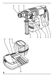
Sawing short workpieces (fig. A4)<br />
It is advisable to use the length stop for short workpieces (32) both for<br />
batch sawing and for short individual workpieces of different lengths.<br />
The length stop can only be used in conjunction with a pair of optional<br />
guide rails (26).<br />
Sawing long workpieces (fig. A3)<br />
Always support long workpieces.<br />
Figure A3 shows the ideal configuration for sawing long workpieces when<br />
the saw is used free-standing (all items available as an option).<br />
These items (except the legstand and the material clamp) are required<br />
both on the infeed and the outfeed side:<br />
- Legstand (31) (supplied with mounting instructions).<br />
- Guide rails (500 or 1,000 mm) (26).<br />
- Stands (30) to support the guide rails. Do not use the stands to<br />
support the machine! The height of the stands is adjustable.<br />
- Material support plates (27).<br />
- Table end plate (25) for supporting the rails (also when working on an<br />
existing bench).<br />
- Material clamp (28).<br />
- Swivelling stop (29).<br />
• Place your saw on the legstand and fit the guide rails.<br />
• Firmly screw the material support plates (27) to the guide rails (26).<br />
The material clamp (28) now functions as a length stop.<br />
• Install the table end plates (25).<br />
• Install the swivelling stop (29) to the rear rail.<br />
• Use the swivelling stop (29) to adjust the length of medium and long<br />
workpieces. It can be adjusted sideways or swung out of the way<br />
when not in use.<br />
Using the roller table (fig. A3 & A5)<br />
The roller table (33) makes the handling of large and long pieces of wood<br />
very easy (fig. A5). It can be connected either to the left or to the right of<br />
the machine. The roller table requires the use of the optional legstand (fig. A3).<br />
Assemble the roller table following the instructions supplied<br />
with the legstand.<br />
• Replace the short support bars provided with the legstand with the<br />
irregular rails from the table on the side the table is to be used.<br />
• Follow all instructions provided with the roller table.<br />
Range of saw blades available (recommended blades)<br />
Tungsten carbide Application Diameter Teeth<br />
tipped (TCT)<br />
Negative tooth For wood, boards 216 24<br />
rake thick-walled plastic profiles<br />
For high-quality panels 216 48<br />
(finer cut), thin-walled<br />
plastic profiles<br />
Negative rake For thin-walled plastic 216 60<br />
flat-topped teeth profiles (e.g. window<br />
blind slats, cable ducts)<br />
21 en - 6