
Create successful ePaper yourself
Turn your PDF publications into a flip-book with our unique Google optimized e-Paper software.
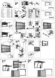
• Lubricate guide pins for tandem drives<br />
(320 or 325).<br />
15<br />
16s<br />
16n<br />
17<br />
NOTE: Make sure that tandem<br />
drives are fitted correctly.<br />
• Push on panel seal (381) from the top<br />
(Euro doors only).<br />
Door vent open / shut<br />
Attach cables<br />
• Loosen one hex-head screw (044) at<br />
each of the two spring tensioning ends<br />
(230).<br />
• Pull the cable ends down (060).<br />
• Raise cable-locking mechanism (359).<br />
• Insert cable eye (061) into cable locking<br />
mechanism (359) and push in pin (358).<br />
• Swing cable-locking mechanism (359)<br />
back as far it will go.<br />
CAUTION! The cable locking<br />
mechanism (359) must be completely<br />
closed. This is the only<br />
way of ensuring that the pin<br />
(358) is locked and the cable<br />
eye (061) secured.<br />
NOTE: The gap between the<br />
door section and the architrave<br />
can be adjusted by moving the<br />
retaining brackets (353/357).<br />
Bolts (358) must be oiled!<br />
Fit low-lintel<br />
cables<br />
• Unroll the low-lintel carrier cable (272)<br />
and thread the end of the cable up<br />
along the door to the low-lintel cable<br />
deflector.<br />
• Raise cable-locking mechanism (359).<br />
• Insert cable eye (061) into cable locking<br />
mechanism (359) and push in pin (358).<br />
• Swing cable-locking mechanism (359)<br />
back as far it will go.<br />
CAUTION! The cable locking<br />
mechanism (359) must be completely<br />
closed. This is the only<br />
way of ensuring that the pin<br />
(358) is locked and the cable<br />
eye (061) secured.<br />
NOTE: The gap between the<br />
door section and the architrave<br />
can be adjusted by moving the<br />
retaining brackets (353/357).<br />
Bolts (358) must be oiled!<br />
Fit door section(s)<br />
• Carefully drive hinge pins (336) into the<br />
tandem holder (330) and inject oil at<br />
lubrication point.<br />
• Mount tandem drives and brackets as<br />
before (Fig. 14.3 /14.4 /14.5).<br />
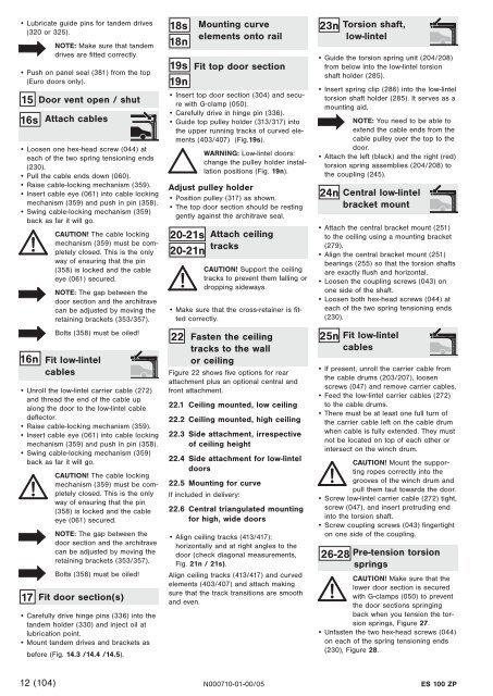
18s<br />
18n<br />
19s<br />
19n<br />
20-21s<br />
20-21n<br />
Mounting curve<br />
elements onto rail<br />
Fit top door section<br />
• Insert top door section (304) and secure<br />
with G-clamp (050).<br />
• Carefully drive in hinge pin (336).<br />
• Guide top pulley holder (313/317) into<br />
the upper running tracks of curved elements<br />
(403/407) (Fig.19s).<br />
WARNING: Low-lintel doors:<br />
change the pulley holder installation<br />
positions (Fig. 19n).<br />
Adjust pulley holder<br />
• Position pulley (317) as shown.<br />
• The top door section should be resting<br />
gently against the architrave seal.<br />
Attach ceiling<br />
tracks<br />
CAUTION! Support the ceiling<br />
tracks to prevent them falling or<br />
dropping sideways.<br />
• Make sure that the cross-retainer is fitted<br />
correctly.<br />
22 Fasten the ceiling<br />
tracks to the wall<br />
or ceiling<br />
Figure 22 shows five options for rear<br />
attachment plus an optional central and<br />
front attachment.<br />
22.1 Ceiling mounted, low ceiling<br />
22.2 Ceiling mounted, high ceiling<br />
22.3 Side attachment, irrespective<br />
of ceiling height<br />
22.4 Side attachment for low-lintel<br />
doors<br />
22.5 Mounting for curve<br />
If included in delivery:<br />
22.6 Central triangulated mounting<br />
for high, wide doors<br />
• Align ceiling tracks (413/417):<br />
horizontally and at right angles to the<br />
door (check diagonal measurements,<br />
Fig. 21n / 21s).<br />
Align ceiling tracks (413/417) and curved<br />
elements (403/407) and attach making<br />
sure that the track transitions are smooth<br />
and even.<br />
26-28<br />
12 (104) N000710-01-00/05 <strong>ES</strong> <strong>100</strong> <strong>ZP</strong><br />
23n<br />
24n<br />
25n<br />
Torsion shaft,<br />
low-lintel<br />
• Guide the torsion spring unit (204/208)<br />
from below into the low-lintel torsion<br />
shaft holder (285).<br />
• Insert spring clip (286) into the low-lintel<br />
torsion shaft holder (285). It serves as a<br />
mounting aid.<br />
NOTE: You need to be able to<br />
extend the cable ends from the<br />
cable pulley over the top to the<br />
door.<br />
• Attach the left (black) and the right (red)<br />
torsion spring assemblies (204/208) to<br />
the coupling (245).<br />
Central low-lintel<br />
bracket mount<br />
• Attach the central bracket mount (251)<br />
to the ceiling using a mounting bracket<br />
(279).<br />
• Align the central bracket mount (251)<br />
bearings (255) so that the torsion shafts<br />
are exactly flush and horizontal.<br />
• Loosen the coupling screws (043) on<br />
one side of the shaft.<br />
• Loosen both hex-head screws (044) at<br />
each of the two spring tensioning ends<br />
(230).<br />
Fit low-lintel<br />
cables<br />
• If present, unroll the carrier cable from<br />
the cable drums (203/207), loosen<br />
screws (047) and remove carrier cables.<br />
• Feed the low-lintel carrier cables (272)<br />
to the cable drums.<br />
• There must be at least one full turn of<br />
the carrier cable left on the cable drum<br />
when cable is fully extended. They must<br />
not be located on top of each other or<br />
intersect on the winch drum.<br />
CAUTION! Mount the supporting<br />
ropes correctly into the<br />
grooves of the winch drum and<br />
pull them taut towards the door.<br />
• Screw low-lintel carrier cable (272) tight,<br />
screw (047), and insert protruding end<br />
into the torsion shaft.<br />
• Screw coupling screws (043) fingertight<br />
on one side of the coupling.<br />
Pre-tension torsion<br />
springs<br />
CAUTION! Make sure that the<br />
lower door section is secured<br />
with G-clamps (050) to prevent<br />
the door sections springing<br />
back when you tension the torsion<br />
springs, Figure 27.<br />
• Unfasten the two hex-head screws (044)<br />
on each of the spring tensioning ends<br />
(230), Figure 28.