MD-500
MD-500
MD-500

Erfolgreiche ePaper selbst erstellen
Machen Sie aus Ihren PDF Publikationen ein blätterbares Flipbook mit unserer einzigartigen Google optimierten e-Paper Software.
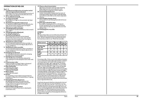
OPERATION OF <strong>MD</strong>-<strong>500</strong><br />
Fig.9 - 12<br />
1 Combined on/of direction of rotation switch<br />
with emergency feature blocked<br />
Switching on the motor and chancing the direction of<br />
stop rotation, the valve kan be blocked with a lock.<br />
2. Drive cupboard closing<br />
For opening and closing of the case<br />
3. Carriage nut handle<br />
By closing the carriage nut, the automatic starting is<br />
switched on.<br />
4. Handwheel longitudinal adjustment<br />
For quickly moving the support to the left and to the<br />
right. On the nonius can be written how big the<br />
adjustment is in steps of 0,04 mm.<br />
5. Clamping handle tool holder<br />
By unloading the handle the bit block can be turned in<br />
steps of 90 °<br />
6. Clamping handle sliding bush<br />
For fixing the sliding bush.<br />
7. Handwheel sliding bush<br />
By turning the piece of work can be clamped<br />
between the chuck and the center; also used for<br />
boring; on the nonius can be written how big the<br />
adjustment is in steps of 0.05 mm.<br />
8. Handwheel crank tool slide<br />
for the longitudinal adjustment of the tool slide; on<br />
the nonius can be written how big the adjustment is<br />
in steps of 0.04 mm.<br />
9. Handwheel crank cross slide<br />
for the longitudinal adjustment of the cross slide; on<br />
the nonius can be written how big the adjustment is<br />
in steps of 0.04 mm.<br />
10 Clamping nut tail stock<br />
for clamping the tail stock to the bed; for clamping<br />
the upper part to the bottomplate.<br />
11 Clamping nuts rotary plate<br />
After the desired corner has been adjusted the<br />
rotary plate parts can be clamped on each other with<br />
this.<br />
12 V-belt tension roller<br />
Makes it possible to change V-belts, to clamp and<br />
shift them without dismantling the pulleys.<br />
13 Main shaft pulley<br />
Adjusting rotary speed.<br />
14 Intermediate pulley<br />
Adjusting rotary speed.<br />
15 Motor pulley<br />
Adjusting rotary speed.<br />
16 Scissor<br />
for assembling an intermediate change wheel and<br />
being able to adjust this in three directions. Coupling<br />
transmission<br />
17 Clamping bolt link adjustment<br />
By adapting the position of the quadrant the<br />
intermediate drive wheel and the transmission<br />
change wheel can be placed. Switching the<br />
transmission on and off.<br />
18 Intermediate change wheel<br />
Direction of rotation transmission; adjusting the<br />
transmission ratio<br />
19 Chance wheel transmission<br />
Adjusting transmission ratio; by means of placing<br />
filling rings the wheel can be adjusted in axial<br />
direction(fig.3) Longitudinal motion support.<br />
20 Transmission/lead screw<br />
Fixation intermediate change wheel; by means of<br />
installing the filling rings he wheel is axial adjustable<br />
and with the lowest shaft nut the wheel is adjustable<br />
sideways<br />
21 Intermediate change wheel<br />
In front of the thread-cutting wheel, behind the starting<br />
wheel<br />
22 Drive gear wheels for start<br />
By using this clamping device for surfacing and<br />
thread-cutting the lock nut can stay open and the<br />
support does not slip away; spindle and nut are less<br />
charged then.<br />
23 Clamping bolt cross slide<br />
CHISELS<br />
Fig.13<br />
During turning a chip is cut out of the piece of work. For<br />
this, chisels have to be sharpened in a special and sharp<br />
form. This form depends on the chisel material and on<br />
the material you want to cut. Watch the next table.<br />
Chisel corners Light cut Normal cut Heavy cut<br />
HSS HM HSS HM HSS HM<br />
Cutting-edge<br />
side rake 1210 10 5 5 0<br />
Clearance<br />
angle 8 6 7 5 6 4<br />
Wedge<br />
angle 70 74 73 80 79 86<br />
Tab.2<br />
On the basis of fig. 13 the corners of this table can be taken<br />
over on a little piece square high-speed steel for making or<br />
re-sharpening your own chisel. In this example we are<br />
talking about a straight, right roughing tool. The dotted<br />
lines indicate the original form of the bar. The sum of the<br />
angles 1,2 and 3 is always 90°. Angle 1 is the cutting-edge<br />
side rake, angle 2 the wedge angle and angle three the<br />
clearance angle. For keeping the friction as low as possible,<br />
two extra clearance angles have been sharpened: angle 4<br />
and angle 6. Besides, a slope angle 5 has been installed. The<br />
arrow indicates the starting direction. The front face is<br />
called the minor cutting face. The main cutting face is the<br />
part on which the arrow has been drawn. In this way all<br />
possible chisels can sharpen themselves, by which you<br />
have to say where the main cutting face has to be and what<br />
the turning material has to be.<br />
A perfectly sharpened chisel has to be placed in the tool<br />
holder in the right way now. Fig.14 indicates a correct<br />
placing of a pointed chisel. Point 1 is the center line. The<br />
tip of the chisel has to stand exactly that high. If not, you<br />
have to use bearing plates(5). The chisel always has to be<br />
placed against the block body(4) and cannot extend<br />
farther than 1 to 1.5 time the tool shank thickness(2).<br />
It goes without saying that all clamping bolts (3) have to<br />
be tightened strongly.<br />
10 Ferm<br />
Ferm 67