MD-500
MD-500
MD-500

Sie wollen auch ein ePaper? Erhöhen Sie die Reichweite Ihrer Titel.
YUMPU macht aus Druck-PDFs automatisch weboptimierte ePaper, die Google liebt.
66 Ferm<br />
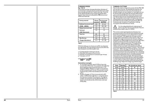
TURNING SPEED<br />
Fig. 15 & 16<br />
If the chisel have been sharpened and put, the piece of<br />
work has been clamped well, the speed of the main shaft<br />
has to be adjusted with the V-belts, watch fig. 15 and 16.<br />
In the subjoined table some machining speeds which<br />
happen many times are indicated for different sorts of<br />
chisels and materials.<br />
Turning material Chissel Turning speed<br />
material REV/MIN<br />
Unalloyed structural steel HSS 40 - 60<br />
(9S20k - 60S20k) P10 140 - 160<br />
Alloyed structural steel HSS 32<br />
Tool steel<br />
(C80= Silversteel)<br />
P10 112<br />
Cast Iron HSS 40<br />
K10 100<br />
Non-Ferrous HSS 45 - 80<br />
(Cupper, Aluminium) K10 140 - 280<br />
Tab.3<br />
With this table you can chose yourself for any diameter<br />
the right speed. The only thing you have to do is fill in the<br />
desired speed in the following formule.<br />
v = Cutting speed in meters per minute<br />
d = Diameter of the piece of work in mm<br />
n = Number of revolutions in revolutions per minute<br />
p = Constant, nl. 3,14<br />
v = x d x n = v x 1000<br />
1000 x d<br />
Calculation example:<br />
1. A round piece of silver steel of 100 mm has to be<br />
turned with a HSS chisel. You can find in the table that<br />
silver steel has to be turned with 32m/min, v=32<br />
Divide 32.000 by 100 gives a number of revolutions<br />
of 320 revolutions per minute. We put belt 2 on the<br />
hindmost discs of the intermediate and main shaft<br />
pulley.<br />
2. A piece of copper of 10 mm is turned with a HMchisel.<br />
v=200 and through that “n” comes far above<br />
the maximum number of revolutions. The highest<br />
number of revolutions can be adjusted. Belt two is<br />
layed on the hindmost disc of the motor and main<br />
shaft pulley.<br />
THREAD-CUTTING<br />
Next to the usual turning work you do with the <strong>MD</strong>-<strong>500</strong><br />
you can also cut screw- thread with this machine. For<br />
this special chisel have to be used. The technique of<br />
thread-cutting is not very simple. For reaching a correct<br />
fit with thread-cutting, both the thread profile and the<br />
minor and outside diameter have to be very accurate.<br />
Therefore many turners use existing machine screw<br />
taps. Screw plates can be used in the same way, however<br />
a fitting holder has to be made yourself. Cutting takes<br />
place with very low numbers of revolutions( often 70<br />
revolutions per minute) or if need be by cranking,<br />
turning the main shaft with your hands.<br />
For the cutting of inchthread, a separate set of<br />
gears is required. This set is not included. This set is<br />
available at your dealer under Nr. 330961.<br />
The continuously repeating distance between two<br />
permanent points of a screw thread is called the thread<br />
haste. If you are going to cut you always have to adjust<br />
this thread haste. This happens by chosing a certain<br />
change wheel com bination on the scissors. In fig.17 on<br />
the left side a single transmission for thread-cutting is<br />
indicated ( a so-called single work) and on the right side a<br />
double transmission for the automatical starting is<br />
indicated( so-called double work). Through this the<br />
support is moved over a certain distance during a<br />
rotation of the main shaft. In the headstock two fixed<br />
transmission have been builded in, namely 1 : 4 for thread<br />
haste and 1 : 40 for starting, which decide the number of<br />
revolutions of the coaxial datum axis. From this datum<br />
the end transmission has to be calculated. For calculating<br />
this some formulas exist, but for the sake of convenience<br />
we already indicated the most current thread haste<br />
dimensions in the subjoined table. All indicated wheels<br />
are delivered automatically with the machine! Installing<br />
or adjusting the change wheels happens by shifting the<br />
scissors and the intermediate wheel axle and by placing<br />
the filling rings. Adjust the change cog-wheels margin.<br />
Pitch Starting Nr. of teeth per wheel<br />
(mm) (mm) AB C<br />
0.4 0.04 49 - 105<br />
0.5 0.05 70 - 84<br />
0.7 0.07 70 98 84<br />
0.8 0.08 105 98 49<br />
1.0 0.1 98 - 42<br />
1.25 0.125 84 105 42<br />
1.5 0.15 105 - 28<br />
1.75 0.175 84 98 28<br />
2.0 0.2 49 98 42<br />
2.5 0.25 63 105 28<br />
3.0 0.3 49 105 30<br />
Tab.4<br />
Ferm 11