MD-500
MD-500
MD-500

Erfolgreiche ePaper selbst erstellen
Machen Sie aus Ihren PDF Publikationen ein blätterbares Flipbook mit unserer einzigartigen Google optimierten e-Paper Software.
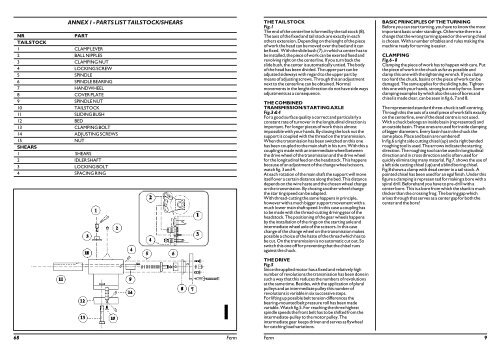
NR PART<br />
TAILSTOCK<br />
1 CLAMP LEVER<br />
2BALL NIPPLES<br />
3 CLAMPING NUT<br />
4 LOCKING SCREW<br />
5 SPINDLE<br />
6 SPINDLE BEARING<br />
7 HANDWHEEL<br />
8 COVER PLATE<br />
9 SPINDLE NUT<br />
10 TAILSTOCK<br />
11 SLIDING BUSH<br />
12BED<br />
13 CLAMPING BOLT<br />
14 ADJUSTING SCREWS<br />
15 NUT<br />
SHEARS<br />
1 SHEARS<br />
2IDLER SHAFT<br />
3 LOCKING BOLT<br />
4 SPACING RING<br />
ANNEX 1 - PARTS LIST TAILSTOCK/SHEARS<br />
1<br />
68 Ferm<br />
THE TAIL STOCK<br />
Fig.1<br />
The end of the centerline is formed by the tail stock (8).<br />
The axis of the fixed and tail stock are exactly in each<br />
others extension. Depending on the lenght of the piece<br />
of work the head can be moved over the bed and it can<br />
be fixed. With the slide bush (7), in which a center has to<br />
be installed, the piece of work can be exerted fixed and<br />
revolving right on the centerline. If you turn back the<br />
slide bush, the center is automatically untied. The body<br />
of the head has been divided. The upper part can be<br />
adjusted sideways with regard to the upper part by<br />
means of adjusting screws. Through this an adjustment<br />
next to the centerline can be obtained. Normal<br />
movements in the lenght direction do not have side ways<br />
adjustments as a consequence.<br />
THE COMBINED<br />
TRANSMISSION/STARTING AXLE<br />
Fig.3 & 4<br />
For a good surface quality a correct and particularly a<br />
constant rate of turnover in the longitudinal direction is<br />
important. For longer pieces of work this is almost<br />
impossible with your hands. By closing the lock nut the<br />
support is coupled with the thread on the transmission.<br />
When the transmission has been switched on this one<br />
has been coupled to the main shaft in his turn. With this a<br />
coupling is made with an intermediate wheel between<br />
the drive wheel of the transmission and the drive wheel<br />
for the longitudinal feed on the headstock. This happens<br />
because of an adjustment of the change wheel scissors,<br />
watch fig. 3 and 4.<br />
At each rotation of the main shaft the support will move<br />
itself over a certain distance along the bed. This distance<br />
depends on the wire haste and the chosen wheel change<br />
on the transmission. By chosing another wheel change<br />
the star ting speed can be adapted.<br />
With thread-cutting the same happens in principle,<br />
however with a much bigger support movement with a<br />
much lower main shaft speed. In this case a coupling has<br />
to be made with the thread-cutting driving gear of the<br />
headstock. The positioning of the gear wheels happens<br />
by the installation of the rings on the starting axle and<br />
intermediate wheel axle of the scissors. In this case<br />
change of the change wheel on the transmission makes<br />
possible a choice of the haste of the thread which has to<br />
be cut. On the transmission is no automatic cut out. So<br />
switch this one off for preventing that the chisel runs<br />
against the chuck.<br />
THE DRIVE<br />
Fig.5<br />
Since the applied motor has a fixed and relatively high<br />
number of revolutions the transmission has been done in<br />
such a way that this reduces the numbers of revolutions<br />
at the same time. Besides, with the application of plural<br />
pulleys and an intermediate pulley this number of<br />
revolutions is variable in six successive steps.<br />
For lifting up possible belt tension differences the<br />
bearing-mounted belt pressure roll has been made<br />
variable. Watch fig.5. For reaching the three highest<br />
spindle speeds the front belt has to be shifted from the<br />
intermediate-pulley to the motor pulley. The<br />
intermediate gear keeps driven and serves as flywheel<br />
for catching load variations.<br />
BASIC PRINCIPLES OF THE TURNING<br />
Before you can start turning, you have to know the most<br />
important basic under standings. Otherwise there is a<br />
change that the wrong turning speed or the wrong chisel<br />
is chosen. With a number of tables and rules making the<br />
machine ready for turning is easier.<br />
CLAMPING<br />
Fig.6 - 8<br />
Clamping the piece of work has to happen with care. Put<br />
the piece of work in the chuck as far as possible and<br />
clamp this one with the tightening wrench. If you clamp<br />
too hard the chuck, basins or the piece of work can be<br />
damaged. The same applies for the sliding tube. Tighten<br />
this one with your hands, strong but not by force. Some<br />
clamping examples by which also the use of bores and<br />
chisel is made clear, can be seen in fig.6, 7 and 8.<br />
The represented standard three-chuck is self-centring.<br />
Through this the axis of a small piece of work falls exactly<br />
on the centerline, even if the dead centre is not used.<br />
With a chuck belongs an inside basin (represented) and<br />
an outside basin. These ones are used for inside clamping<br />
of bigger diameters. Every basin has in the chuck the<br />
same place. Place and basin are numbered!<br />
In fig.6 a right side cutting chisel (up) and a right bended<br />
roughing tool is used. The arrows indicate the starting<br />
direction. The roughing tool can be used in longitudinal<br />
direction and in cross direction and is often used for<br />
quickly elimina ting many material. Fig 7. shows the use of<br />
a left side cutting chisel (up) and a blind boring chisel.<br />
Fig.8 shows a clamp with dead center in a tail stock. A<br />
pointed chisel has been used for an egal finish. Under this<br />
figure a clamping is represen ted for making a bore with a<br />
spiral drill. Beforehand you have to pre-drill with a<br />
center bore. This is a bore from which the shank is much<br />
thicker than the crossing frog. The boring gap which<br />
arises through that serves as a center gap for both the<br />
center and the bore!<br />
Ferm 9