MD-500
MD-500
MD-500

Sie wollen auch ein ePaper? Erhöhen Sie die Reichweite Ihrer Titel.
YUMPU macht aus Druck-PDFs automatisch weboptimierte ePaper, die Google liebt.
When the tail stock (8) is placed next to the centerline<br />
because of cross adjustment, an outward conical plane is<br />
turned. An extra processing possibility over the lenght<br />
axle is cutting a screw-thread. A special chisel cuts a<br />
spiral deepening in the outline of the piece of work. A<br />
part of the outline keeps on standing and this height<br />
difference forms the ultimate screw-thread. Next to<br />
turning over the lenght axle, the ends of a piece of work<br />
can also be processed, for example for making them flat<br />
and straight. Short pieces of work can be fixed at one<br />
side in a fixed turning-point, the three-jaw chuck, and on<br />
the other side be processed at right angles to the<br />
centerline. The basins of the chuck see to maintenance<br />
of an imaginary centerline. By having occurred the chisel<br />
replace ment under an angle by adjustment of the chuck,<br />
inward and outward conical planes can be turned. With<br />
this strain borings can also be made in levelled surfaces.<br />
For that a drill chuck has to be bought separately. This<br />
drill chuck with morse cone peg has to be installed in the<br />
sliding tube (7) of the tail stock. Then the gaps can be<br />
screwn out until the desired depht, diameter and form.<br />
The precision of the pieces of work is first and<br />
particularly depen dant of expertness and<br />
experience. During turning many factors can influence the<br />
end result, like the sort and the condition of the chisels, the<br />
nature of the material you want to process, the turn and<br />
starting speed, the fixation of the piece of work, the drafting<br />
and the condition of the machine. With the <strong>MD</strong>-<strong>500</strong> it is<br />
possible to manufacture prolonged pieces of work with a big<br />
accuracy, if all circumstances are perfect.<br />
FOR THE BEGINNING TURNER<br />
During turning big powers on certain parts can be<br />
developed. If you use the machine incorrect these parts<br />
can be damaged or deformed and wear end tear faster,<br />
even if they have been made and designed very expertly<br />
and carefully. Through this the accuracy of the machine<br />
will decrease strongly, which directly influences the<br />
quality and tahe preciseness of your pieces of work. So it<br />
is important that the apparatus is tended in an expert<br />
way. Recommended is, if you are not a skilled turner, to<br />
start with simple pieces of work and to try the different<br />
possibilities of the lathe with trial pieces of work. It is<br />
instructive to look at skilled turners, because you are not<br />
that fast a perfect turner! For pre venting<br />
disappointments you have to become familiar with the<br />
basic principles of turning. Turning is not for nothing a<br />
profession. You can find referencebooks about metal<br />
working and metal turning in the library or in a bookshop.<br />
Besides model-building magazines write about this<br />
subject regularly. The best is getting into possession of a,<br />
if need be obsolete, technical text-book. In this book is<br />
told about the general principles of turning and many<br />
things worth knowing and handy summaries of problems<br />
with possible causes and solutions.<br />
FUNCTION OF THE MACHINE<br />
Fig.1<br />
For a good understanding of the working of the machine<br />
this one can for conve nience sake be divided in a number<br />
of main groups and components, all with a special<br />
function. Watch fig.1.<br />
THE MACHINE BED<br />
Fig.2<br />
The machine bed connects all these parts and has next to<br />
it also other important functions. The bed (3) has been<br />
manufactured of highgrade grey cast iron and it is<br />
provided with several filled cross ties. Because of the<br />
design and the applied sorts of material tremblings are<br />
better absorbed and deforming because of charge is<br />
minimum. The bed is provided with two sliding surfaces<br />
sharpened very precisely, for the conducting of support<br />
and tail stock. These conduc tings, one prismatic and one<br />
flat, see to maintenance of the centerline(4).watch fig.2.<br />
THE MOTOR<br />
The attached alternating current motor is a carbon<br />
brushless 1-phase squirrel- cage motor with starting<br />
condenser. The motor is maintenancefree and does not<br />
need a special treatment. By means of V-belts and plural<br />
belt discs, the pulleys, the movement of the motor is<br />
transmitted to the mains axis.<br />
THE HEADSTOCK<br />
Fig.A<br />
The poured headstock(1) has been fixed on the bed with<br />
a prism conducting and two face plates. On the back side<br />
is an oil draining nut. The cover is remo vable for<br />
inspection and for putting oil. At the bottom of the head<br />
you can find a system of turning axis and toothed wheels.<br />
Because of these toothed wheels the speed of the main<br />
shaft is retarded and transmitted to a double, coaxial<br />
output axis. On this axis you can find the driving gear for<br />
the start and the driving gear for the thread-cutting,<br />
watch fig.B. In the head you can find the most important<br />
part of the machine, the main shaft(2).<br />
This one has been fixed revolving with two conical roller<br />
bearings in an O- drafting. All turning parts in the head<br />
are lubricated by means of an oil bath. The level of this is<br />
readable in the window on the front side. The main shaft<br />
has been provided with a going on boring with on the<br />
right side a fixing flange and a morse cone, for<br />
respectively the chucks and the center.<br />
THE SUPPORT<br />
Fig.1<br />
On the sliding surfaces on the bed the support(5) has been<br />
fixed which sees that conducting tools along the piece of<br />
work is checked. First the support consists of a bed slide<br />
with lock case. This slide lies on the bed and serves as<br />
movement in the lenght direction. This movement can<br />
occur with the hands or automatically by the<br />
transmission/feeding axis(6). In the last case the coach bolt<br />
has to be closed in the lock case. On the bed slide a second<br />
slide has been installed which takes care of the chisel<br />
movement in cross direction. By means of a spindle with<br />
follow nut this slide can be moved or adjusted. On the<br />
cross slide a chuck has been installed. With this the upper<br />
slide or tool slide can be adjusted under an angle. The third<br />
and upper slide, tool slide, can be replaced in any desired<br />
direction over a distance of 70 mm and it follows every<br />
movement of all underlying slides also the chuck. On top of the tool<br />
slide a tool holder has been installed. In this tool can be exerted to a<br />
point height of maximum 15 mm, the vertical distance to the<br />
centerline. The tool holder has a fourfold absorption and has an<br />
indexing pin with four click points. Through this can be changed of<br />
chisel very fast without having to adjust again.<br />
8 Ferm<br />
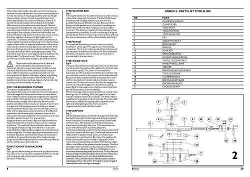
ANNEX 2 - PARTS LIST TOOLSLIDE<br />
NR PART<br />
1 CLAMPING SCREWS<br />
2CLAMP LEVER<br />
3 TOOL POST<br />
4 TOOL POST PIN<br />
5 TOOL SLIDE TOP<br />
6 KEY<br />
7 ADJUSTING BOLT<br />
8 SPINDLE NUT<br />
9 SPINDLE<br />
10 SUNK KEY<br />
11 SPINDLE BEARING<br />
12SOCKET HEAD SCREWS<br />
13 CASTLE LOCKING NUT<br />
14 HANDWHEEL LEVER<br />
15 VERNIER<br />
16 DRIVING PLATE LOCK NUT<br />
17 TOOL SLIDE BASE<br />
18 CLAMPING BOLT<br />
19 DRIVING PLATE BASE<br />
20 PIN DRIVING PLATE<br />
21 CROSS SLIDE KEY<br />
2<br />
Ferm 69