90-269-01 MicroStop dt.qxd - KLS Martin
90-269-01 MicroStop dt.qxd - KLS Martin
90-269-01 MicroStop dt.qxd - KLS Martin

Sie wollen auch ein ePaper? Erhöhen Sie die Reichweite Ihrer Titel.
YUMPU macht aus Druck-PDFs automatisch weboptimierte ePaper, die Google liebt.
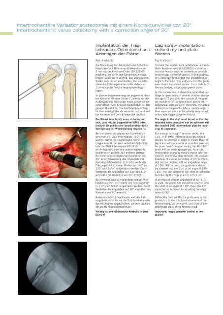
Intertrochantäre Varisationsosteotomie mit einem Korrekturwinkel von 20°<br />
Intertrochanteric varus osteotomy with a correction angle of 20°<br />
145° - 130°<br />
Implantation der Tragschraube,<br />
Osteotomie und<br />
Anbringen der Platte<br />
Abb. 6 a/b/c/d:<br />
Zur Markierung der Antetorsion des Schenkelhalses<br />
wird mit Hilfe eines Bildwandlers ein<br />
2 mm starker Kirschner-Draht (25-228-00)<br />
möglichst zentral in den Schenkelhals eingebracht.<br />
Dabei ist es wichtig, den vorgeplanten<br />
Winkel zum Schaft einzuhalten. Die Eintrittsstelle<br />
des Führungsdrahtes sollte dabei ca.<br />
1 cm distal der Trochanterapophysenfuge<br />
liegen.<br />
In diesem Zusammenhang sei angemerkt, dass<br />
bei kleineren Kindern (unter 7 Jahren) auf der<br />
Außenseite des Trochanter major schon vor der<br />
eigentlichen Fuge Knorpel nachweisbar ist. Der<br />
genaue Abstand zur Trochanterapophysenfuge<br />
ist also meist größer als vermutet und wird erst<br />
bei Kontrolle mit dem Bildwandler deutlich.<br />
Der Winkel zum Schaft muss so bemessen<br />
sein, dass mit der ausgewählten DMS Intermediate<br />
die gewünschte Varuskorrektur durch<br />
Verringerung der Winkelstellung möglich ist.<br />
Bei normalem bis valgischem Schenkelhals<br />
wird man die DMS Intermediate 110°–145°<br />
wählen, damit die Tragschraube mittig zum<br />
Liegen kommt, bei eher varischem Schenkelhals<br />
die DMS Intermediate 80°–110°.<br />
Im Prinzip wird also eine anatomiegerechte<br />
Implantation geplant. Mit anderen Worten:<br />
Bei einer beabsichtigten Varuskorrektur von<br />
20° unter Verwendung des Implantats mit<br />
dem Angulationssektor 110–145° sollte der<br />
Führungsdraht in einem Winkel von 145° bis<br />
130° zum Schaft eingebracht werden. Durch<br />
Verstellen der Angulation auf 125° bis 110°<br />
wird dann die Korrektur von 20° erreicht.<br />
Bei Verwendung des Implantates mit der Winkelstellung<br />
80°–110° sollte der Führungsdraht<br />
in 110° zum Schaft eingebracht werden. Durch<br />
Verstellen der Angulation auf <strong>90</strong>° wird dann die<br />
Korrektur von 20° erreicht.<br />
Anders als beim Erwachsenen wird der Führungsdraht<br />
nicht bis vor die Subchondrallamelle<br />
des Hüftkopfes vorgeschoben, sondern bis kurz<br />
vor die Hüftkopfepiphysenfuge.<br />
Wichtig ist eine Bildwandler-Kontrolle in zwei<br />
Ebenen!<br />
Lag screw implantation,<br />
osteotomy and plate<br />
fixation<br />
Fig. 6 a/b/c/d:<br />
To mark the femoral neck antetorsion, a 2-mmthick<br />
Kirschner wire (25-228-00) is inserted<br />
into the femoral neck as centrally as possible<br />
under image converter control. In this process,<br />
it is important to maintain the predetermined<br />
angle to the shaft. The entry point of the guide<br />
wire should be located approx. 1 cm distally of<br />
the trochanteric apophyseal growth plate.<br />
In this connection, it should be noted that cartilage<br />
is identifiable in smaller children (below<br />
the age of 7 years) on the outside of the greater<br />
trochanter of the femur even before the<br />
apophyseal plate as such. Therefore, the actual<br />
distance to the growth plate is usually larger<br />
than expected and can be reliably determined<br />
only under image converter control.<br />
The angle to the shaft must be set so that the<br />
intended varus correction can be achieved with<br />
the selected DMS Intermediate plate by reducing<br />
its angulation.<br />
For normal to “valgic” femoral necks, the<br />
110–145° DMS Intermediate plate should<br />
usually be selected in order to ensure that the<br />
lag screw will come to lie in a central position;<br />
for more “varic” femoral necks, the 80–110°<br />
plate will be more appropriate. As a rule,<br />
implantation planning should always take the<br />
specific anatomical requirements into account.<br />
Example: if a varus correction of 20° is intended<br />
and an implant with an angulation range<br />
of 110–145° is used, the guide wire should<br />
be inserted into the shaft at an angle of 145–<br />
130°. The 20° correction will then be achieved<br />
by reducing the angulation to 125–110°.<br />
If an implant with an angulation of 80–110°<br />
is used, the guide wire should be inserted into<br />
the shaft at an angle of 110°. Here, the 20°<br />
correction is achieved by adjusting the angulation<br />
to <strong>90</strong>°.<br />
Differently from adults, the guide wire is not<br />
pushed up to the subchondral lamella of the<br />
femoral head, but to a point just short of the<br />
epiphyseal plate of the femoral head.<br />
Important: image converter control in two<br />
planes!