90-269-01 MicroStop dt.qxd - KLS Martin
90-269-01 MicroStop dt.qxd - KLS Martin
90-269-01 MicroStop dt.qxd - KLS Martin

Sie wollen auch ein ePaper? Erhöhen Sie die Reichweite Ihrer Titel.
YUMPU macht aus Druck-PDFs automatisch weboptimierte ePaper, die Google liebt.
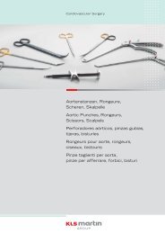
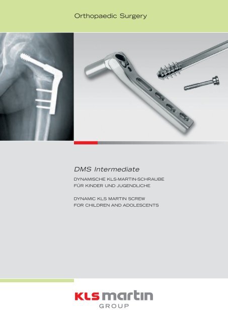
Orthopaedic Surgery<br />
DMS Intermediate<br />
DYNAMISCHE <strong>KLS</strong>-MARTIN-SCHRAUBE<br />
FÜR KINDER UND JUGENDLICHE<br />
DYNAMIC <strong>KLS</strong> MARTIN SCREW<br />
FOR CHILDREN AND ADOLESCENTS
DMS Intermediate<br />
Dynamische <strong>KLS</strong>-<strong>Martin</strong>-Schraube<br />
für Kinder und Jugendliche<br />
110°<br />
Dynamic <strong>KLS</strong> <strong>Martin</strong> Screw<br />
80°<br />
for children and adolescents<br />
Einleitung<br />
Die DMS Intermediate ist 1/3 kleiner als die DMS-<br />
Standard-Platte und somit an die Verhältnisse des<br />
kindlichen Femurknochens angepasst. Gleichzeitig<br />
werden dabei die Vorteile der intraoperativen Winkeleinstellung<br />
des Implantates bewahrt.<br />
Vorteile<br />
• Ideale Schaftkongruenz<br />
• Vor- und rückschneidende Tragschraube<br />
• Exaktes intra-operatives Einstellen des<br />
CCD-Winkels<br />
• Sekundäre Valguskorrekturmöglichkeit<br />
• Beste biomechanische Verhältnisse und hohe<br />
Belastungsstabilität auch in schwierigen Fällen<br />
• Einfache OP-Technik<br />
• Geringe Komplikationsrate<br />
• Stark reduzierte Vorratshaltung<br />
Exklusiv bei <strong>KLS</strong> <strong>Martin</strong><br />
Indikationen<br />
Varisations-, Valgisations-, Rotations- oder Verkürzungsosteotomie<br />
des proximalen Femurs bei:<br />
•<br />
•<br />
•<br />
•<br />
•<br />
•<br />
Angeborener Hüftdysplasie, insbesondere Hüftluxation<br />
Neurogener Hüftdysplasie mit Hüftsubluxation,<br />
z.B. bei Infantiler Cerebralparese oder Spina bifida<br />
Coxa valga, vara, antetorta oder retrotorta<br />
Morbus Perthes<br />
Epiphyseolysis capitis femoris<br />
Beinlängendifferenz<br />
Supracondyläre Varisations-, Valgisationsoder<br />
Rotationsosteotomie bei:<br />
• X-Bein, O-Bein oder Drehfehler<br />
Altersbereich ca. 5-16 Jahre<br />
Gewichtsgrenze max. 60 kg empfohlen<br />
Es liegen auch Erfahrungen mit der DMS Intermediate<br />
bei kleinwüchsigen Erwachsenen zur Versorgung von<br />
stabilen Schenkelhalsfrakturen vor.<br />
Kontraindikationen<br />
• Sehr kleiner Femurknochen<br />
• Kinder unter oder über der Alters- oder<br />
über der Gewichtsgrenze
3<br />
145°<br />
110°<br />
Introduction<br />
The DMS Intermediate is 1/3 smaller than the<br />
DMS standard plate. Therefore it is adapted to the<br />
proportions of the femur in children. At the same<br />
time the advantage of changing the angulation of<br />
the plate intraoperatively is maintained.<br />
Advantages<br />
• Ideal shaft congruence<br />
• Forward and backward cutting Lag Screw<br />
• Exact intraoperative adjustment of the<br />
collodiaphyseal angle (valgisation, reduction)<br />
• Optional secondary valgus correction<br />
• Optimal biomechanical situation and<br />
high stability under load condition<br />
• Simple surgical technique<br />
• Low complication rate<br />
• Strongly reduced stock-keeping<br />
Exclusive with <strong>KLS</strong> <strong>Martin</strong><br />
Indications<br />
Proximal femoral varus, valgus, rotational or<br />
shortening osteotomy in:<br />
•<br />
•<br />
•<br />
•<br />
•<br />
•<br />
Developmental hip dysplasia, especially<br />
hip dislocation<br />
Neurogenic hip dysplasia with hip subluxation/<br />
dislocation, e. g. in cerebral palsy or myelomeningocele<br />
Coxa valga, vara, antetorta or retrotorta<br />
Legg-Calvé-Perthes’ disease<br />
Slipped upper femoral epiphysis<br />
Leg length discrepancy<br />
Supracondylar varus, valgus or rotational osteotomy in:<br />
• Genu valgum, varum or rotational deformities<br />
Age range approx. 5-16 years<br />
Weight limit max. 60 kg recommended<br />
The DMS Intermediate has also been successfully<br />
tested in adults of small stature for fixation of stable<br />
femoral neck fractures.<br />
Contraindications<br />
• Very small femur<br />
• Children below/above the age range<br />
or over the weight limit
3 Hole<br />
4 Hole<br />
6 Hole<br />
8 Hole<br />
25-178-04<br />
25-178-06<br />
25-178-08<br />
Gebrüder <strong>Martin</strong> GmbH & Co. KG<br />
A company of the <strong>KLS</strong> <strong>Martin</strong> Group · Ludwigstaler Str. 132 · D-78532 Tuttlingen · Postfach 60 · D-785<strong>01</strong> Tuttlingen<br />
Tel. +49 7461 706-0 · Fax +49 7461 706-193 · info@klsmartin.com · www.klsmartin.com<br />
3 Hole<br />
4 Hole<br />
6 Hole<br />
8 Hole<br />
Gebrüder <strong>Martin</strong> GmbH & Co. KG<br />
A company of the <strong>KLS</strong> <strong>Martin</strong> Group · Ludwigstaler Str. 132 · D-78532 Tuttlingen · Postfach 60 · D-785<strong>01</strong> Tuttlingen<br />
Tel. +49 7461 706-0 · Fax +49 7461 706-193 · info@klsmartin.com · www.klsmartin.com<br />
Intertrochantäre Varisationsosteotomie mit einem Korrekturwinkel von 20°<br />
Intertrochanteric varus osteotomy with a correction angle of 20°<br />
Präoperative Planung der<br />
Korrekturosteotomie<br />
Preoperative planning of<br />
the corrective osteotomy<br />
Abb. 1:<br />
Zur präoperativen Planung muss das Ausmaß<br />
der Varuskorrektur genau bestimmt werden.<br />
Anhand dessen wird dann die DMS Intermediate<br />
mit dem passenden Angulationssektor<br />
(80–110°: 25-179-XX / 110–145°: 25-178-XX)<br />
ausgewählt. Für die Detailplanung ist eine<br />
Röntgenübersichtsaufnahme des Beckens oder<br />
eine a.p.-Aufnahme der Hüfte erforderlich.<br />
Bei Coxa antetorta empfehlen sich Aufnahmen<br />
in Innenrotation und bei Hüftdezentrierung in<br />
Abduktion (evtl. kombiniert in jeweils 20°–30°).<br />
Fig. 1:<br />
As part of the preoperative planning, the scope<br />
of the varus correction needs to be determined<br />
with precision. On this basis, the DMS Intermediate<br />
plate is then selected, making sure<br />
that it has the correct angulation (80–110°:<br />
25-179-XX / 110–145°: 25-178-XX). Detailed<br />
planning requires a pelvic X-ray view or an AP<br />
X-ray of the hip.<br />
In cases of coxa antetorta, it is best to take<br />
X-rays under medial rotation. For decentered<br />
hips, abduction is recommended (the two can<br />
be combined, 20°–30° each).<br />
Abduktion 20°<br />
20° abduction<br />
Innenrotation 20°<br />
20° internal rotation<br />
Abb. 2:<br />
Vom Röntgenbild wird eine Papierpause hergestellt.<br />
Der Papier-Femurknochen wird ausgeschnitten<br />
und die erwünschte Korrektur nach<br />
Durchtrennung im Osteotomiebereich eingestellt.<br />
Dies kann mit oder ohne Keilentnahme,<br />
d.h. lateral aufklappend oder medial zuklappend,<br />
erfolgen. Zusätzlich wird mit Hilfe einer<br />
Röntgenschablone die voraussichtliche Lage<br />
der DMS Intermediate vor und nach der<br />
„Osteotomie“ eingezeichnet. Die Röntgenschablonen<br />
weisen einen Maßstab von 1:1 auf.<br />
Mit Hilfe dieser „Papierchirurgie“ lässt sich<br />
sowohl die Endposition der Fragmente mit der<br />
in der Regel angestrebten Medialisierung des<br />
distalen Fragments als auch die neue Position<br />
des Hüftkopfes in der Pfanne gut vor Augen<br />
führen.<br />
Da eine Beinverkürzung meist unerwünscht ist<br />
(Ausnahme: Luxationshüfte), bietet sich bei<br />
der Varusosteotomie die Entscheidung für eine<br />
lateral aufklappende Osteotomie ohne mediale<br />
Keilentnahme an. Die DMS Intermediate ist<br />
auf Grund ihrer Variabilität und Stabilität dafür<br />
gut geeignet. Eine eventuelle Rotationskorrektur<br />
wird nach dem klinischen Befund (prä- und<br />
auch intraoperativ) bzw. entsprechend der präoperativen<br />
Antetorsionsbestimmung mittels<br />
Rippstein-I- und -II-Röntgenaufnahmen vorgenommen.<br />
Fig. 2:<br />
A paper tracing is made from the X-ray image.<br />
The paper femur template is then cut out and<br />
the desired correction is set after dissection in<br />
the osteotomy region. This can be performed<br />
with or without the wedge removal i.e. lateral<br />
opening or medial closing osteotomy. The prospective<br />
position of the DMS Intermediate plate<br />
before and after “osteotomy” is sketched in as<br />
well, using a template. The X-ray templates<br />
used have a 1:1 scale.<br />
Such “paper surgery” is very useful for visualizing<br />
both the final positions of the fragments<br />
(with medialization of the distal fragments, as<br />
usually desirable) and the new position of the<br />
femoral head in its socket.<br />
20°<br />
Varisation um 20°<br />
20° varization<br />
Valgisation um 20°<br />
20° valgization<br />
20°<br />
35 40 50 60 70 80 <strong>90</strong> 100<br />
110°<br />
100°<br />
<strong>90</strong>°<br />
35 40 50 60 70 80 <strong>90</strong> 100 80°<br />
DMS intermediate lag screw<br />
25-178-03<br />
3540 50 60 70 80 <strong>90</strong> 100<br />
145°<br />
140°<br />
130°<br />
120°<br />
35 40 50 60 70 80 <strong>90</strong> 100<br />
DMS intermediate lag screw<br />
25-179-03<br />
25-179-04<br />
25-179-06<br />
110°<br />
As leg shortening is undesirable in most cases<br />
(exception: hip displacement), varus osteotomy<br />
is preferably performed as a lateral opening<br />
osteotomy without medial wedge removal.<br />
The DMS Intermediate plate is well suited for<br />
this purpose due to its variability and stability.<br />
Should a rotational correction be necessary as<br />
well, this is done according to the (pre- and<br />
also intraoperative) clinical findings, or according<br />
to the antetorsion angle determined preoperatively<br />
by means of Rippstein I and II<br />
X-rays.<br />
25-179-08<br />
DMS intermediate - Template Scale 1:1<br />
DMS intermediate - Template Scale 1:1<br />
<strong>90</strong>-325-52-21<br />
<strong>90</strong>-325-52-22<br />
<strong>90</strong>-325-52-22 <strong>90</strong>-325-52-21
5<br />
Lagerung<br />
Patient positioning<br />
Abb. 3:<br />
Der Patient wird in Rückenlagerung auf einem<br />
durchleuchtbaren OP-Tisch positioniert. Beide<br />
Beine werden beweglich abgedeckt. Während<br />
des Eingriffs kann der Operateur dann die<br />
Rotation und Beinlänge mit der der Gegenseite<br />
vergleichen. Auch bei einer einseitigen Operation<br />
bietet sich dies an. Zusätzlich ist es günstig,<br />
ein röntgendurchlässiges Kissen oder ein<br />
gefaltetes Tuch unter das Sacrum zu platzieren,<br />
damit Becken und Oberschenkel etwas angehoben<br />
werden. Die Oberschenkelweichteile sind<br />
dann von lateral besser zugänglich.<br />
Sollte während der Operation auch eine Beckenosteotomie<br />
geplant sein, wird beim Abdecken<br />
der Beckenkamm bis Höhe Rippenbogen einbezogen.<br />
Fig. 3:<br />
The patient is positioned dorsally on a transilluminable<br />
operating table. Both legs are<br />
covered flexibly. This enables the surgeon<br />
to compare rotation and leg length with the<br />
opposite side during the intervention. This is<br />
recommended also for unilateral operations.<br />
Besides, it is advisable to place a radiolucent<br />
cushion or folded towel underneath the sacrum<br />
in order to lift the pelvis and thighs a little,<br />
as this facilitates lateral access to the soft<br />
parts of the thigh.<br />
If pelvic osteotomy is additionally planned for<br />
the same session, the iliac crest is covered as<br />
well up to costal arch level.<br />
Zugang<br />
Approach<br />
Abb. 4:<br />
Der Zugang erfolgt über einen lateralen Oberschenkellängsschnitt,<br />
der von knapp distal der<br />
Trochanterspitze bis zum proximalen Femurschaft<br />
geführt wird. Die Inzision sollte so lang<br />
sein, dass die Platte der DMS Intermediate<br />
leicht am Schaft fixiert werden kann. Die Faszie<br />
wird im Faserverlauf gespalten. Dabei wird<br />
das Bein in leichter Abduktion gehalten, um<br />
die Faszienspannung zu verringern. Wenn nötig,<br />
kann eine entlastende Kerbung des dorsalen<br />
Faszienlappens durchgeführt werden. Die Bursa<br />
trochanterica wird eröffnet und nach ventral<br />
und dorsal abgeschoben.<br />
Fig. 4:<br />
Surgical access is made by means of a lateral<br />
longitudinal thigh incision from a point slightly<br />
distally of the tip of the trochanter to the proximal<br />
shaft of the femur. The incision should be<br />
long enough to permit easy fixation of the DMS<br />
Intermediate plate to the shaft. The fascia is<br />
split along the course of the fibers, with the leg<br />
kept in a slightly abducted position to reduce<br />
fascia tension. If necessary, the dorsal lobe<br />
of fascia can be notched to relieve tension.<br />
Thereafter, the trochanteric bursa is opened<br />
and the tissue retracted ventrally and dorsally.<br />
Abb. 5:<br />
Das Freilegen der intertrochantären Femurregion<br />
erfolgt entweder unter L-förmigem<br />
Abhängen des Vastus lateralis oder unter Bildung<br />
von je einem langen Glutaeus-medius-<br />
Lappen – Vastus-lateralis-Lappen, ventral und<br />
dorsal. Zur guten Orientierung empfiehlt es<br />
sich, den Trochanter soweit subperiostal freizulegen,<br />
dass ventral der Beginn des Schenkelhalses<br />
tast- bzw. sichtbar wird.<br />
Fig. 5:<br />
The intertrochanteric femoral region must now<br />
be exposed, either by L-shaped detachment<br />
of the vastus lateralis muscle or by forming a<br />
long gluteus-medius/vastus-lateralis flap both<br />
ventrally and dorsally. To ensure good orientation,<br />
subperiosteal exposure of the trochanter<br />
is recommended until the proximal end of the<br />
femoral neck is ventrally palpable and visible.
Intertrochantäre Varisationsosteotomie mit einem Korrekturwinkel von 20°<br />
Intertrochanteric varus osteotomy with a correction angle of 20°<br />
145° - 130°<br />
Implantation der Tragschraube,<br />
Osteotomie und<br />
Anbringen der Platte<br />
Abb. 6 a/b/c/d:<br />
Zur Markierung der Antetorsion des Schenkelhalses<br />
wird mit Hilfe eines Bildwandlers ein<br />
2 mm starker Kirschner-Draht (25-228-00)<br />
möglichst zentral in den Schenkelhals eingebracht.<br />
Dabei ist es wichtig, den vorgeplanten<br />
Winkel zum Schaft einzuhalten. Die Eintrittsstelle<br />
des Führungsdrahtes sollte dabei ca.<br />
1 cm distal der Trochanterapophysenfuge<br />
liegen.<br />
In diesem Zusammenhang sei angemerkt, dass<br />
bei kleineren Kindern (unter 7 Jahren) auf der<br />
Außenseite des Trochanter major schon vor der<br />
eigentlichen Fuge Knorpel nachweisbar ist. Der<br />
genaue Abstand zur Trochanterapophysenfuge<br />
ist also meist größer als vermutet und wird erst<br />
bei Kontrolle mit dem Bildwandler deutlich.<br />
Der Winkel zum Schaft muss so bemessen<br />
sein, dass mit der ausgewählten DMS Intermediate<br />
die gewünschte Varuskorrektur durch<br />
Verringerung der Winkelstellung möglich ist.<br />
Bei normalem bis valgischem Schenkelhals<br />
wird man die DMS Intermediate 110°–145°<br />
wählen, damit die Tragschraube mittig zum<br />
Liegen kommt, bei eher varischem Schenkelhals<br />
die DMS Intermediate 80°–110°.<br />
Im Prinzip wird also eine anatomiegerechte<br />
Implantation geplant. Mit anderen Worten:<br />
Bei einer beabsichtigten Varuskorrektur von<br />
20° unter Verwendung des Implantats mit<br />
dem Angulationssektor 110–145° sollte der<br />
Führungsdraht in einem Winkel von 145° bis<br />
130° zum Schaft eingebracht werden. Durch<br />
Verstellen der Angulation auf 125° bis 110°<br />
wird dann die Korrektur von 20° erreicht.<br />
Bei Verwendung des Implantates mit der Winkelstellung<br />
80°–110° sollte der Führungsdraht<br />
in 110° zum Schaft eingebracht werden. Durch<br />
Verstellen der Angulation auf <strong>90</strong>° wird dann die<br />
Korrektur von 20° erreicht.<br />
Anders als beim Erwachsenen wird der Führungsdraht<br />
nicht bis vor die Subchondrallamelle<br />
des Hüftkopfes vorgeschoben, sondern bis kurz<br />
vor die Hüftkopfepiphysenfuge.<br />
Wichtig ist eine Bildwandler-Kontrolle in zwei<br />
Ebenen!<br />
Lag screw implantation,<br />
osteotomy and plate<br />
fixation<br />
Fig. 6 a/b/c/d:<br />
To mark the femoral neck antetorsion, a 2-mmthick<br />
Kirschner wire (25-228-00) is inserted<br />
into the femoral neck as centrally as possible<br />
under image converter control. In this process,<br />
it is important to maintain the predetermined<br />
angle to the shaft. The entry point of the guide<br />
wire should be located approx. 1 cm distally of<br />
the trochanteric apophyseal growth plate.<br />
In this connection, it should be noted that cartilage<br />
is identifiable in smaller children (below<br />
the age of 7 years) on the outside of the greater<br />
trochanter of the femur even before the<br />
apophyseal plate as such. Therefore, the actual<br />
distance to the growth plate is usually larger<br />
than expected and can be reliably determined<br />
only under image converter control.<br />
The angle to the shaft must be set so that the<br />
intended varus correction can be achieved with<br />
the selected DMS Intermediate plate by reducing<br />
its angulation.<br />
For normal to “valgic” femoral necks, the<br />
110–145° DMS Intermediate plate should<br />
usually be selected in order to ensure that the<br />
lag screw will come to lie in a central position;<br />
for more “varic” femoral necks, the 80–110°<br />
plate will be more appropriate. As a rule,<br />
implantation planning should always take the<br />
specific anatomical requirements into account.<br />
Example: if a varus correction of 20° is intended<br />
and an implant with an angulation range<br />
of 110–145° is used, the guide wire should<br />
be inserted into the shaft at an angle of 145–<br />
130°. The 20° correction will then be achieved<br />
by reducing the angulation to 125–110°.<br />
If an implant with an angulation of 80–110°<br />
is used, the guide wire should be inserted into<br />
the shaft at an angle of 110°. Here, the 20°<br />
correction is achieved by adjusting the angulation<br />
to <strong>90</strong>°.<br />
Differently from adults, the guide wire is not<br />
pushed up to the subchondral lamella of the<br />
femoral head, but to a point just short of the<br />
epiphyseal plate of the femoral head.<br />
Important: image converter control in two<br />
planes!
7<br />
Abb. 7:<br />
Bei korrekter Position wird die Länge des<br />
Führungsdrahtes im Knochen mit der Messhülse<br />
(25-228-05) bestimmt, z.B. 50 mm.<br />
Der Dreistufenbohrer (25-228-12) wird auf<br />
den Messwert minus 5 mm eingestellt, also<br />
45 mm, weil der Kegel der 3. Bohrstufe mit<br />
5 mm berücksichtigt werden muss. Bitte achten<br />
Sie beim Lösen der Rändelschraube darauf,<br />
dass ein Linksgewinde vorliegt und somit im<br />
Uhrzeigersinn gedreht und die Rändelschraube<br />
komplett abgezogen werden muss.<br />
Fig. 7:<br />
Once positioned correctly, the length of the<br />
guide wire inside the bone is determined<br />
with the measuring sleeve (25-228-05)<br />
(e.g. 50 mm). The triple reamer (25-228-12)<br />
is then set to the measured value minus 5 mm<br />
(i.e. 45 mm) in order to account for the cone<br />
of the third stage of the reamer (5 mm). When<br />
loosening the knurled nut, please note that this<br />
is a left-hand thread (to be turned clockwise!)<br />
and that the nut must be removed completely.<br />
Abb. 8:<br />
Über den Führungsdraht wird unter Spülung<br />
soweit vorgebohrt, bis der Kegel der 3. Bohrstufe<br />
in der lateralen Kortikalis versenkt ist.<br />
Beim Aufbohren mit der Einstellung von beispielsweise<br />
45 mm wird eine wahre Bohrtiefe<br />
von 50 mm erreicht. Implantiert wird aber eine<br />
Tragschraube von 45 mm Länge – passend zur<br />
eingestellten Bohrtiefe.<br />
Das Bohren sollte auf jeden Fall unter Bildwandlerkontrolle<br />
stattfinden, damit der Führungsdraht<br />
nicht unabsichtlich bis in die Fuge<br />
vorgeschoben wird, bzw. bei einer Fehlmessung<br />
eine Bohrung bis in die Fuge erfolgt. Bei einem<br />
Bohrerdurchmesser von 6 mm wäre eine Fugenschädigung<br />
die Folge, welche das Risiko einer<br />
Schenkelhalswachstumsstörung nach sich ziehen<br />
würde.<br />
Abb. 9 a/b:<br />
Der Gewindeschneider wird bis zur wahren<br />
Bohrtiefe (z.B. von 50 mm) eingebracht –<br />
ablesbar anhand der Skalierung auf Höhe der<br />
lateralen Kortikalis. Beim Eindrehen des Gewindeschneiders<br />
(25-228-17) ist darauf zu<br />
achten, dass nicht überdreht wird. Sonst würde<br />
das Gewinde im Knochen zerstört und die Verankerung<br />
der Tragschraube gefährdet werden.<br />
Fig. 8:<br />
Pre-drilling is done via the guide wire under irrigation<br />
until the cone of the third stage is fully<br />
immersed in the lateral cortex. When using a<br />
setting of 45 mm for pre-drilling for example,<br />
the true drilling depth is 50 mm. The implanted<br />
lag screw, however, has a length of 45 mm –<br />
in line with the preset drilling depth.<br />
In any case, it is important to do the pre-drilling<br />
under image converter control to prevent the<br />
guide wire from being inadvertently pushed forward<br />
too far (i.e. right into the growth plate), and<br />
also to prevent accidental drilling into the growth<br />
plate in case of wrong measurement. Given a<br />
drill bit diameter of 6 mm, growth plate damage<br />
would inevitably be caused by such an error,<br />
with a consequential risk of femoral neck growth<br />
disturbance.<br />
Fig. 9 a/b:<br />
The tap is inserted to the true drilling depth<br />
(e.g. 50 mm). This can be checked via the<br />
scale marks at the level of the lateral corticalis.<br />
When screwing in the tap (25-228-17), be sure<br />
not to overturn it, as stripping (destroying) the<br />
thread inside the bone would jeopardize proper<br />
lag screw anchorage.<br />
Abb. 10:<br />
Entsprechend der auf dem 3-Stufen-Bohrer<br />
eingestellten Bohrtiefe wird die Tragschraube<br />
(25-170-xx) in der gleichen Länge ausgewählt<br />
(z.B. von 45 mm).<br />
An diese wird die Tragschraubendreherhülse<br />
(25-228-06) mittels Verbindungsanker<br />
(25-228-20) montiert. Erst dann erfolgt<br />
das Eindrehen mittels Zusatzhülse für Tragschraubendreher<br />
(25-228-21) und T-Handgriff<br />
(25-238-08).<br />
Fig. 10:<br />
The selected lag screw (25-170-xx) must<br />
match the drilling depth set on the triple<br />
reamer (e.g. 45 mm).<br />
Using the lag screw connector (25-228-20),<br />
the screw is first fitted with the lag screw<br />
inserter (25-228-06) before it is finally inserted<br />
using the safety inserter (25-228-21)<br />
and the T-handle (25-238-08).
Intertrochantäre Varisationsosteotomie mit einem Korrekturwinkel von 20°<br />
Intertrochanteric varus osteotomy with a correction angle of 20°<br />
Abb. 11:<br />
Nun kann die entsprechende DMS-Intermediate-<br />
Platte probeweise eingesetzt werden. Dies geschieht<br />
durch Aufschieben der zylindrischen<br />
Lasche über den Tragschraubendreher auf die<br />
Tragschraube und Anlegen der Platte an den<br />
Femurschaft. Wegen des 6-kantigen Designs der<br />
Tragschraube stellt sich die Platte nicht unbedingt<br />
parallel zum Femurschaft ein. In diesem<br />
Fall muss der T-Griff mit Zusatzhülse noch einmal<br />
aufgesetzt und die Tragschraube etwas voroder<br />
zurückgedreht werden.<br />
Fig. 11:<br />
Now the selected DMS Intermediate plate can<br />
be inserted for testing purposes. This is done<br />
by pushing the cylindrical (barrel) part of the<br />
plate over the screwdriver onto the lag screw.<br />
Then the plate is attached to the shaft of the<br />
femur. Due to the hexagonal design of the lag<br />
screw, the plate may initially be out of line<br />
with the femoral shaft. In this case, attach<br />
the T-handle with the safety inserter again and<br />
adjust the lag screw by rotating it a little forward<br />
or backward.<br />
Abb. 12:<br />
Danach werden die Zusatzhülse, der Verbindungsanker<br />
und die Tragschraubendreherhülse<br />
entfernt und die Platte durch Veränderung der<br />
Winkelstellung über die Justierschraube mit dem<br />
2,5-mm-Inbus-Schraubendreher (22-368-24)<br />
genau an den Femurschaft angepasst. Damit ist<br />
die Winkelstellung definiert, von der aus die<br />
Varuskorrektur vorgenommen wird. Unter der<br />
Voraussetzung, dass keine zusätzliche Rotationskorrektur<br />
eingeplant ist (s. u.), kann die Platte<br />
mit einer proximal (osteotomienah) ins Langloch<br />
gesetzten Schraube vorübergehend fixiert<br />
werden. Das definitive Anbringen der Platte<br />
wird dadurch erleichtert. Die osteotomienahe<br />
Platzierung der Schraube ist wichtig, damit die<br />
Platte bei lateral aufklappender Osteotomie<br />
nach proximal rutschen kann. Zur Durchführung<br />
der Osteotomie wird die Laschenplatte<br />
wieder entfernt, ohne zunächst die Winkelstellung<br />
zu verändern. Die Tragschraube bleibt<br />
in ihrer definitiven Lage.<br />
Fig. 12:<br />
Thereafter, the safety inserter, the lag screw<br />
connector and the lag screw inserter are removed<br />
and the plate is adapted accurately to the<br />
femoral shaft by adjusting its angulation via<br />
the adjusting screw, using the 2.5-mm Allen<br />
screwdriver (22-368-24). This defines the<br />
angular position used as a basis for varus<br />
correction. Provided that no additional rotational<br />
correction is required (see below), the plate<br />
can be temporarily fixed in place with a screw<br />
placed proximally into the elongated hole (next<br />
to the osteotomy). This facilitates the final<br />
attachment of the plate. Screw placement close<br />
to the osteotomy is important in order to allow<br />
for proximal plate movement when performing<br />
a lateral opening osteotomy. To perform the<br />
osteotomy, the barrel plate is removed again<br />
while leaving the angle position unchanged for<br />
the time being. The lag screw remains in its<br />
final position.<br />
Abb. 13:<br />
Zur Markierung der Rotation bzw. Planung<br />
einer Rotationskorrektur erfolgt das Einbringen<br />
von zwei Kirschner-Drähten von ca. 2,5 mm<br />
Stärke ventral oder ventrolateral in den Femur,<br />
proximal und distal der geplanten Osteotomie.<br />
Anmerkung zur Veränderung der Rotation beim<br />
Morbus Perthes:<br />
Die im Verlauf der Erkrankung häufig nachweisbare<br />
Einschränkung der Innenrotation<br />
muss selten korrigiert werden. Es handelt sich<br />
nicht um eine Verminderung der Antetorsion,<br />
sondern um eine arthrogene Störung, die sich<br />
beim weiteren Remodelling von Kopf und<br />
Pfanne bessert. Außerdem wird das Innenrotationsdefizit<br />
funktionell gut toleriert.<br />
Fig. 13:<br />
To mark the rotation, or plan the rotational<br />
correction, two Kirschner wires with a thickness<br />
of approx. 2.5 mm are inserted into the<br />
femur ventrally or ventrolaterally, proximally<br />
and distally of the planned osteotomy.<br />
Note concerning the rotation change in<br />
patients with Perthes’ disease:<br />
It is seldom necessary to correct the restriction<br />
of internal rotation that frequently occurs in<br />
the course of the disease, as this is not a condition<br />
of reduced antetorsion but, rather, an<br />
arthrogenous disorder that will improve again<br />
as a result of further head and socket remodelling.<br />
Besides, the internal rotation deficit is<br />
tolerated well in functional terms.
9<br />
Abb. 14:<br />
Die Osteotomie wird, knapp distal des Eindrehlochs<br />
für die Tragschraube, so nach medial<br />
geführt, dass der größte Teil des Trochanter<br />
minor stehen bleibt. Bei der Varusosteotomie<br />
muss der Abstand zum Eindrehloch auch deshalb<br />
knapp sein, weil die distale laterale Kante<br />
des proximalen Fragments bei der Angulation<br />
in Varus gegen die Platte stoßen könnte. Wenn<br />
die Osteotomie annähernd quer zum Schaft<br />
erfolgt, wird eine eventuelle Rotationskorrektur<br />
erleichtert. Bewährt hat sich das Vorlegen eines<br />
Kirschner-Drahtes, an dem distal entlang<br />
gesägt wird.<br />
Nach Vollendung des Sägeschnitts erfolgt ein<br />
betontes Aufspreizen der Osteotomie mit einem<br />
Knochenspreizer, um die Weichteile zu lockern.<br />
Die Fragmente werden in die geplante Varuskorrektur<br />
gebracht. Wenn dabei Schwierigkeiten<br />
auftreten, ist es besser, eine (hälftige) Keilresektion<br />
medial vorzunehmen und den Keil<br />
lateral in die Lücke zu platzieren, als eine<br />
spannungsbedingte Bewegungseinschränkung<br />
zu riskieren. Diese könnte die Nachbehandlung<br />
erschweren bzw. ein ergänzendes Weichteil-<br />
Release erforderlich machen.<br />
Fig. 14:<br />
Just distally of the lag screw insertion hole, the<br />
osteotomy is performed towards medial in such<br />
a way that the largest part of the trochanter<br />
minor is left in place. For varus osteotomies,<br />
the distance from the insertion hole must be<br />
small also because the distal lateral edge of<br />
the proximal fragment might otherwise knock<br />
against the plate in varus angulation. Performing<br />
the osteotomy nearly transversally to the<br />
shaft will facilitate rotational correction if<br />
required as well. Preplacement of a Kirschner<br />
wire that can be used as a guide for the distal<br />
saw cut has proved useful.<br />
Completion of the saw cut is followed by a<br />
marked widening of the osteotomy gap using<br />
a bone spreader in order to release the soft<br />
tissues. Then the fragments are put in position<br />
according to the planned varus correction.<br />
If this is difficult, it is better to perform (half)<br />
a wedge resection medially and then insert the<br />
wedge into the gap laterally – instead of risking<br />
a loss of motion caused by tension, which<br />
could make follow-up treatment difficult or<br />
might require additional soft-tissue release.<br />
Unterstellung<br />
Sub-positioning<br />
a b c<br />
Abb. 15:<br />
Illustration der bei der Varusosteotomie<br />
gewünschten medialen Unterstellung des<br />
Schaftes unter das proximale Fragment:<br />
a) normaler Kraftverlauf<br />
b) zu wenig Unterstellung<br />
c) korrekte Unterstellung<br />
Fig. 15:<br />
Illustration of the medial sub-positioning of the<br />
shaft under the proximal fragment as intended<br />
by varus osteotomy:<br />
a) normal force profile<br />
b) insufficient sub-positioning<br />
c) correct sub-positioning<br />
Abb. 16:<br />
Nun kann das Originalimplantat eingesetzt<br />
werden. Dabei kann eventuell ein leichtes<br />
Nachschlagen mit dem Platten-Einschläger<br />
(25-228-14) notwendig sein. Danach erfolgt<br />
das Einschrauben der Kompressionsschraube<br />
(25-170-99), welche leicht angezogen wird.<br />
Durch Drehung der Justierschraube im Uhrzeigersinn<br />
(1 Drehung = 7,5°) wird die Angulation<br />
entsprechend verringert. Die vorläufige<br />
Fixierung der Laschenplatte am Schaft erfolgt<br />
mit einer Verbrugge-Zange.<br />
Die Überprüfung der Rotation und eine evtl.<br />
Korrektur empfiehlt sich in Hüftbeugung und<br />
-streckung.<br />
Es ist nicht ratsam, die Korrektur in 20° Varus<br />
bei vorläufig fixierter Platte nur über das<br />
Schneckengetriebe zu versuchen. Zur Überwindung<br />
der Gewebespannung müsste die Justierschraube<br />
mit großem Kraftaufwand gedreht<br />
werden. Dabei würde die Inbus-Steckverbindung<br />
zwischen Schraubendreher und Schraube<br />
extrem beansprucht und mit großer Wahrscheinlichkeit<br />
insuffizient. Die Angulation könnte<br />
dann ebenfalls nicht mehr verändert werden.<br />
Fig. 16:<br />
Now the original implant can be inserted.<br />
This may require slight correction with the<br />
plate impactor (25-228-14). Thereafter, the<br />
compression screw (25-170-99) is inserted<br />
and slightly tightened.<br />
The angulation is reduced as appropriate<br />
by rotating the adjusting screw clockwise<br />
(1 turn = 7.5°). Verbrugge forceps are used<br />
to fix the barrel plate temporarily in place<br />
on the shaft.<br />
The rotation check, with correction if necessary,<br />
should be performed with the hip bent as well<br />
as extended.<br />
It is not recommended to attempt to perform<br />
the 20° varus correction, with the plate fixed<br />
provisionally, only via the worm gear because<br />
too much force would be required to overcome<br />
the tissue tension by turning the adjusting<br />
screw, which would very likely lead to failure<br />
of the screwdriver/screw interface due to overstressing<br />
the screw head socket. This would<br />
also mean that subsequent adjustment of the<br />
angulation would no longer be possible.
Intertrochantäre Varisationsosteotomie mit einem Korrekturwinkel von 20°<br />
Proximal varus osteotomy with a correction angle of 20°<br />
Abb. 17 a/b/c:<br />
Mit selbstschneidenden 3,5-mm-Kortikalisschrauben<br />
(25-103-xx) wird die Platte endgültig fixiert.<br />
Nach Möglichkeit sollte die erste Schraube in<br />
Kompressionsstellung in das proximale Gleitloch<br />
eingebracht werden, damit sich die Fragmente<br />
etwas einstauchen (z. B. bei der aufklappenden<br />
Osteotomie und gleichzeitigen Medialisierung<br />
des distalen Fragments).<br />
Wenn die Osteotomie in aufklappender Technik<br />
durchgeführt wird, empfiehlt sich eine Spongiosaplastik<br />
in den lateral klaffenden Spalt<br />
durch Einschieben von Spongiosa aus den Osteotomieflächen<br />
und/oder die Transplantation von<br />
1–2 mm dicken lokalen Kortikalis-Chips.<br />
Abschließend erfolgt eine Bildwandler-Dokumentation<br />
in zwei Ebenen.<br />
Fig. 17 a/b/c:<br />
The plate is finally fixed in place with selftapping<br />
3.5-mm cortical screws (25-103-xx).<br />
If possible, the first screw should be inserted<br />
into the proximal sliding hole in compression<br />
position so the fragments are impacted a little<br />
(e.g. in opening osteotomies with simultaneous<br />
medialization of the distal fragment).<br />
When performing an opening osteotomy, it is<br />
recommended to fill the lateral gap by using<br />
a spongiosaplasty (inserting cancellous bone<br />
substance from the osteotomy surfaces) and/or<br />
transplanting local cortical chips with a thickness<br />
of 1–2 mm.<br />
Finally, the result is documented in two planes<br />
by image converter.<br />
Wundverschluss<br />
Große Spülung. Gute Refixierung des Vastus, falls dieser L-förmig<br />
abgehängt wurde. Weiterer schichtweiser Wundverschluss unter adaptierender<br />
Naht der Bursa. Bei Bedarf 1 – 2 Drains. Nur im Ausnahmefall<br />
Becken-Bein-Fuß-Gips, da bei korrekter Implantation Übungsstabilität<br />
erreicht wird, in der Regel sogar Teilbelastungsstabilität.<br />
Wound closure<br />
Thorough irrigation of the wound. Good refixation of the vastus lateralis<br />
muscle if it has been detached by an L-shaped incision. Then layerby-layer<br />
wound closure with loose suturing of the trochanteric bursa.<br />
If necessary, use of 1 or 2 drains. Only in exceptional cases, application<br />
of a long-leg (pelvis-leg-foot) spica cast because correct implantation<br />
of the DMS Intermediate plate leads to solid fixation allowing<br />
early range-of-motion exercises if not partial weight bearing.<br />
Nachbehandlung<br />
Am 2. oder 3. postoperativen Tag Röntgen: Beckenübersicht (A.P.) und<br />
Hüftübersicht axial nach Lauenstein. Etwa ab 3. postoperativen Tag<br />
Behandlung mit Motorschiene und Mobilisierung im (Liege-)Rollstuhl<br />
oder mit Gehwagen bzw. an Unterarmgehstützen (meist unter Teilbelastung).<br />
Entlassung am 5.–7. postoperativen Tag. Nach 6 Wochen<br />
Röntgenkontrolle und Entscheidung über Vollbelastung.<br />
Nach 3–4 Monaten Metallentfernung, so dass auch wieder eine<br />
Kernspintomographie möglich ist (z.B. bei Morbus Perthes). Vorgehen<br />
umgekehrt zum Einbau: Entfernung von Kompressionsschraube,<br />
Laschenplatte und Tragschraube. Es empfiehlt sich eine Auffüllung<br />
des Schraubenkanals mit Spongiosa oder mit 1–2 mm starken Kortikalis-Chips<br />
aus der Nachbarschaft des Plattenlagers. Sicherheitshalber<br />
Teilbelastung an Unterarmgehstützen für 4–6 Wochen und Sportkarenz<br />
für 3–4 Monate.<br />
Follow-up-treatment<br />
On the 2 nd or 3 rd postoperative day, radiographic assessment: pelvic<br />
view (A.P.) and axial hip view (Lauenstein position). Begin with mobilization<br />
on about the 3 rd postoperative day with range of motion exercises<br />
including use of a continuous passive motion device and transfer<br />
in a wheelchair in recumbent position. Alternatively, mobilization with<br />
a walking frame or forearm crutches (as a rule with partial weight<br />
bearing). Discharge on the 5 th to 7 th postoperative day. After six weeks,<br />
radiographic follow-up and decision about full weight bearing.<br />
Implant removal is envisaged after three to four months allowing MR<br />
imaging again, for instance in case of Legg-Calvé-Perthes disease.<br />
Inverse procedure: removal of the compression screw, barrel plate,<br />
and lag screw. It is recommended to fill the resulting bone void in the<br />
femoral neck with cancellous bone or 1–2 mm thick cortical chips<br />
from around the plate bed. As a precaution, partial weight bearing with<br />
forearm crutches for 4–6 weeks is recommended. No sports for 3–4<br />
months.
Fall 1<br />
Case 1<br />
11<br />
Neurogene Hüftsubluxation rechts<br />
bei beinbetonter Tetraspastik<br />
Rollstuhlabhängigkeit.<br />
7 1/2-jähriges Mädchen<br />
26 kg Körpergewicht.<br />
Neurogenic subluxation of the right<br />
hip in cerebral palsy with marked<br />
lower extremity spasticity<br />
Wheelchair dependency.<br />
7 1/2-year-old girl.<br />
26 kg body weight.<br />
Abb. 1: Beckenübersichtsaufnahme in Spontanhaltung.<br />
Subluxation der rechten Hüfte.<br />
Fig. 1: A.P. pelvic view in rest position. Subluxation of the right hip.<br />
Abb. 2: Beckenübersichtsaufnahme in Abduktion und 25° Innenrotation.<br />
Die rechte Hüfte hat sich nur gering in Abduktion und Innenrotation einstellen<br />
lassen. Weiterbestehende Subluxationsstellung des Kopfes. Hinweis<br />
auf Weichteilkontraktur, d. h. spastische Verkürzung der Adduktoren und<br />
medialen Kniebeuger.<br />
Fig. 2: A.P. pelvic view in abduction and 25° of medial rotation. The right hip<br />
could be positioned only in slight abduction and medial rotation. The head<br />
remained subluxated indicating spastic shortening of the adductors and<br />
medial hamstrings.<br />
Abb. 3: Postoperatives Resultat.<br />
Fig. 3: Postoperative result.<br />
Abb. 4: Endergebnis nach Plattenentfernung.<br />
Fig. 4: Final result after removal of the implant.<br />
Operation<br />
•<br />
•<br />
•<br />
•<br />
Intertrochantäre Varisationsosteotomie rechts,<br />
lateral aufklappend um 20°, 3-Loch-Laschenplatte<br />
Pemberton-Salter-Azetabuloplastik mit solidem<br />
Hydroxylapatit-Keil<br />
Antero-mediales Hüft-Release mit Abhängen des Psoas<br />
Tenotomie des Semitendinosus und intramuskuläre<br />
Verlängerung Semimembranosus<br />
Surgery<br />
•<br />
•<br />
•<br />
•<br />
Proximal varus osteotomy of the right femur,<br />
lateral opening wedge in 20° varus, 3-hole barrel plate<br />
Pemberton-Salter acetabuloplasty with use of a solid<br />
hydroxyapatite wedge<br />
Anteromedial hip release with detachment of the psoas<br />
Tenotomy of the semitendinosus and intramuscular<br />
lengthening of the semimembranosus<br />
Verlauf<br />
Erfolgreiche Rezentrierung des rechten Hüftkopfes. Implantat<br />
zeitgerecht entfernt. Bleibende Rollstuhlabhängigkeit.<br />
Postoperative course<br />
Successful reduction of the right femoral head. Timely<br />
removal of the implant. Lasting wheelchair dependency.
Fall 2<br />
Case 2<br />
Epiphyseolysis capitis femoris links,<br />
Grad III<br />
Späte Erstverstellung. Zunächst subkapitale Osteotomie<br />
nach Dunn-Fish mit begrenzter Aufrichtung des Kopfes.<br />
Verzögerte knöcherne Konsolidierung bei eingeschränkter<br />
Compliance (viel zu frühe Vollbelastung).<br />
Keine Entwicklung einer Kopfnekrose. Beinlängendifferenz<br />
(- 2,5 cm links). Femoroazetabuläres Impingement.<br />
16-jähriger Junge. 66 kg Körpergewicht.<br />
Slipped upper femoral epiphysis<br />
on the left, grade III<br />
Late presentation. Initial treatment by subcapital cuneiform<br />
osteotomy according to Dunn-Fish with limited correction.<br />
Delayed bony consolidation because of poor compliance<br />
(early full weight bearing). Fortunately no development of<br />
a vascular necrosis. Leg length discrepancy (- 2.5 cm on<br />
the left). Femoroacetabular impingement.<br />
16-year-old boy. 66 kg body weight at operation.<br />
Abb. 1a: A.P.-Röntgenaufnahme der linken Hüfte: Verzögerte knöcherne<br />
Heilung nach subkapitaler Keilosteotomie nach Dunn-Fish.<br />
Fig. 1a: A.P. view of the left hip in standing position giving evidence of delayed<br />
bony union after a subcapital wedge osteotomy according to Dunn-Fish.<br />
Abb. 1b: Korrespondierende Axialaufnahme.<br />
Fig. 1b: Corresponding axial view of the left hip.<br />
Abb. 2: Postoperative Röntgenaufnahmen der linken Hüfte (A.P. und axial)<br />
nach Korrekturosteotomie nach Imhäuser-Weber.<br />
Fig. 2: Postoperative radiographs of the left hip (A.P. and axial view) after<br />
a corrective osteotomy according to Imhäuser-Weber.<br />
Operation<br />
• Intertrochantäre Valgisations-Flexions-Derotationsosteotomie<br />
n. Imhäuser-Weber links, medial aufklappend im<br />
25° Valgus, ventral zuklappend in 20° Flexion (= Hüftextension),<br />
gering in Innenrotation. 4-Loch-Laschenplatte,<br />
Langloch mit zwei Schrauben besetzt. Platzierung der Tragschraube<br />
in das Lager der unteren Spongiosaschraube.<br />
• Knochentransplantation in den medialen Osteotomiespalt<br />
(zerkleinerter ventraler Keil).<br />
Abb. 3: Röntgenaufnahmen der linken Hüfte (A.P. und axial)<br />
nach knöcherner Konsolidierung der Osteotomie.<br />
Fig. 3: Radiographs of the left hip (A.P. and axial view)<br />
after bony consolidation of the osteotomy.<br />
Surgery<br />
• Proximal osteotomy of the left femur in valgus, flexion and<br />
derotation (according to Imhäuser-Weber), medial opening<br />
wedge in 25° valgus, ventral closing wedge in 20° flexion<br />
(i. e. in hip extension) and slight medial rotation. 4-hole barrel<br />
plate, two screws were placed in the sliding hole. Insertion of<br />
the lag screw into the tract of the inferior cancellous screw.<br />
• Transplantation of morsellised bone into the medial open wedge<br />
(bone material obtained from the resected ventral wedge).<br />
Verlauf<br />
Postoperativ gegen ärztliche Anweisung (wieder früher Übergang<br />
zur Vollbelastung). Diesmal guter knöcherner Durchbau<br />
der Osteotomie. Zeitnahe Entfernung der Implantate. Patient<br />
bei deutlich verbesserter Beweglichkeit und Verringerung<br />
der Beinlängendifferenz auf ca. 1 cm zufrieden. Wünscht<br />
keine weitere Therapie. Radiologisch leichte Arthrosezeichen.<br />
Mittelfristige Gelenkprognose günstig. Langfristig muss mit<br />
der Notwendigkeit einer frühen Endoprothesenversorgung<br />
gerechnet werden. Ohne Korrekturosteotomie wäre auch die<br />
mittelfristige Prognose ungünstig gewesen.<br />
Postoperative course<br />
Against doctor's orders again early full weight bearing. This<br />
time good bony consolidation of the osteotomy. Timely removal<br />
of the implants. Patient satisfied with notably improved<br />
range of motion and reduction of leg length discrepancy to<br />
1 cm. Does not desire further therapy. Radiographs give<br />
evidence of beginning osteoarthritic changes. Favourable<br />
mid-term prognosis of the joint. In the long-term the patient<br />
will need a total hip replacement. Without the Imhäuser-<br />
Weber corrective osteotomy even mid-term prognosis would<br />
have been guarded.
Fall 3<br />
Case 3<br />
13<br />
Coxa vara links mit Trochanterhochstand<br />
bei proximalem fokalem Femur-<br />
Defekt (Pappas VII)<br />
Hüftdysplasie. Beinlängendifferenz (- 14 cm links).<br />
Zustand nach Trochanterapophyseodese.<br />
Femoroazetabuläres Impingement.<br />
11-jähriger Junge.<br />
42 kg Körpergewicht.<br />
Coxa vara with high riding of the<br />
greater trochanter in proximal femoral<br />
focal deficiency (type Pappas VII)<br />
Hip dysplasia. Leg length discrepancy (- 14 cm on the left).<br />
Precedent trochanteric apophysiodesis.<br />
Femoroacetabular impingement.<br />
11-year-old boy.<br />
42 kg body weight.<br />
im Stand<br />
Abb. 1: Beckenübersichtsaufnahme im Stand: Coxa vara links mit Trochanterhochstand.<br />
Fig. 1: A.P. pelvic view in standing position demonstrating coxa vara with high<br />
riding greater trochanter.<br />
Abb. 2: Präoperative Planungsskizze bzw. "Papierchirurgie".<br />
Fig. 2: Preoperative planning sketch, "paper surgery" respectively.<br />
Abb. 3: Intraoperative Bildwandleraufnahme. An der Position der K-Drähte<br />
lässt sich die Korrektur in Valgus erkennenn.<br />
Fig. 3: Intraoperative fluoroscopic image. The position of the K-wires indicates<br />
the varus correction.<br />
Operation<br />
• Intertrochantäre Valgisationsosteotomie links,<br />
medial aufklappend um 15°, mit leichter Lateralisierung<br />
des Schaftes<br />
Tragschraube 40 mm, 4-Loch-Laschenplatte<br />
(nur 3 Löcher besetzt)<br />
• Knochentransplantation in den medialen Osteotomiespalt<br />
• Release des Tractus iliotibialis distal<br />
Verlauf<br />
Verzögerte Konsolidierung. Leichter Korrekturverlust.<br />
Entfernung des Implantats nach über einem Jahr.<br />
Bruch von zwei Kortikalisschrauben, aber kein Hinweis<br />
auf Materialversagen der Laschenplatte.<br />
Abb. 4: Unmittelbar postoperatives Röntgenbild.<br />
Fig. 4: Immediate postoperative radiograph.<br />
Surgery<br />
•<br />
•<br />
•<br />
Proximal valgus osteotomy of the left femur,<br />
medial opening wedge of 15°, slight lateralization<br />
of the shaft<br />
Lag screw of 40 mm, 4-hole barrel plate<br />
(only three holes occupied)<br />
Bone transplantation into the medial osteotomy gap<br />
Distal release of the iliotibial tract<br />
Postoperative course<br />
Delayed bony union. Moderate loss of correction. Removal<br />
of the implant after more than a year. Breakage of two cortical<br />
screws but no evidence of barrel plate fatigue failure.
Fall 4<br />
Case 4<br />
Posttraumatisches Genu valgum<br />
et recurvatum rechts<br />
bei anterolateraler Überbrückung der distalen<br />
Femurepiphysenfuge und ventraler Überbrückung<br />
der proximalen Tibiaepiphysenfuge. Deutliches<br />
Kniebeugedefizit.<br />
14-jährige Jugendliche.<br />
56 kg Körpergewicht.<br />
Post-traumatic valgus and extension<br />
deformity of the right knee<br />
due to anterolateral bridging of the distal femoral<br />
growth plate and ventral bridging of the proximal<br />
tibial growth plate. Significant knee flexion deficit.<br />
14-year-old girl.<br />
56 kg body weight.<br />
Abb. 1a: Präoperative Röntgenaufnahme beider Beine im Stand.<br />
Genu Valgum rechtsseitig.<br />
Fig. 1a: Preoperative radiograph of both legs in standing position<br />
demonstrating genu valgum on the right side.<br />
Abb. 1b: Nahaufnahme präoperativ. Lesionen an der Epiphysenfuge am<br />
rechten distalen Femur und der rechten proximalen Tibia.<br />
Fig. 1b: Preoperative close view of both knees in standing position. Growth<br />
plate lesions can be noted in the right distal femur and the right proximal tibia.<br />
Fig. 2: A.P.-Aufnahme des rechten Knies direkt post-operativ.<br />
Fig. 2: A.P. radiograph of the right knee immediately post-operative.<br />
Fig. 3: A.P.-Aufnahme im Stand vor Explantation des Implantats.<br />
Gute Ausrichtung des rechten Beins.<br />
Fig. 3: A.P. radiograph of both legs in standing position shortly before<br />
removal of the implant. Good alignment of the right leg.<br />
Operation<br />
•<br />
•<br />
•<br />
•<br />
Supracondyläre Varisationsosteotomie rechts,<br />
10° lateral aufklappend in Varus und leicht in Flexion<br />
Tragschraube 60 mm, 4-Loch-Laschenplatte<br />
Epiphyseodese n. Phemister distaler Femur medial<br />
Desepiphyseodese proximale Tibia ventral mit<br />
Fettlappen-Interposition (nach Langenskiöld)<br />
Knochentransplantation in den lateralen Osteotomiespalt<br />
(Spongiosa von der Tibia und 1–2 mm<br />
dicke Kortikalis-Chips vom Femur)<br />
Surgery<br />
• Supracondylar varus osteotomy of the right femur,<br />
lateral opening wedge in 10° varus and slight flexion<br />
Lag screw of 60 mm, 4-hole barrel plate<br />
• Epiphysiodesis of the distal medial femur (Phemister<br />
technique)<br />
• Resection of a physeal bar in the proximal ventral tibia<br />
with free fat interposition (Langenskiöld technique)<br />
• Transplantation of bone into the lateral osteotomy gap<br />
(cancellous bone from the tibia and 1–2 mm thick<br />
cortical chips from the femur)<br />
Verlauf<br />
Zeitgerechter knöcherner Durchbau. Bei der Metallentfernung<br />
Auffüllung des Schraubenlagers mit Kortikalis-<br />
Chips. Nach 6 Wochen Vollbelastung. Beugedefizit 15°<br />
gebessert. Patientin mit Beweglichkeit und Kosmetik<br />
zufrieden. Keine weiteren Maßnahmen gewünscht.<br />
Postoperative course<br />
Timely bony consolidation. At removal of the implant filling<br />
of the intramedullary bone void with cortical chips. Six<br />
weeks later full weight bearing. Increase of knee flexion by<br />
15°. Patient satisfied with range of motion and cosmetic.<br />
No further treatment desired.
Fall 5<br />
Case 5<br />
15<br />
Mediale Schenkelhalsfraktur,<br />
Typ 31B1-2 nach der AO-Klassifikation<br />
Stabil in leichter Valgusposition eingestauchte<br />
subkapitale Fraktur.<br />
Patientin, 85 Jahre alt.<br />
Medial intracapsular femoral neck<br />
fracture, type 31B1-2 according to<br />
the AO Classification<br />
In slight valgus position impacted, stable subcapital<br />
fracture.<br />
85-year-old female patient.<br />
Abb. 1: Unfalltag.<br />
Fig. 1: Post-accident A.P. pelvic radiograph.<br />
Abb. 2: Postoperative Röntgenkontrolle.<br />
Fig. 2: Postoperative A.P. radiograph of the right hip.<br />
Abb. 3a: Röntgenkontrolle nach 2 Wochen, A.P.-Ebene.<br />
Fig. 3a: A.P. pelvic view after two weeks.<br />
Abb. 3b: Röntgenkontrolle nach 2 Wochen, axiale Ebene.<br />
Fig. 3b: Axial view of the right hip after two weeks.<br />
Abb. 4: Vollbelastungssituation nach knöcherner Konsolidierung<br />
6 Monate postoperativ.<br />
Fig. 4: A.P. pelvic view 6 months postoperative. There is bony<br />
consolidation allowing full weight bearing.
Implantate<br />
Implants<br />
St Stahl/Steel STERILE R<br />
1 VE/Unit(s)<br />
DMS-Intermediate-Platten, Winkelstellung 80° - 110°<br />
DMS Intermediate plates, angle adjustment 80° - 110°<br />
DMS-Intermediate-Platten, Winkelstellung 110° - 145°<br />
DMS Intermediate plates, angle adjustment 110° - 145°<br />
145°<br />
110°<br />
110°<br />
80°<br />
19 mm Länge des Laschenzylinders<br />
19 mm barrel length<br />
Implantate<br />
Implants<br />
Löcher/holes<br />
3 25-178-03 St 1<br />
4 25-178-04 St 1<br />
6 25-178-06 St 1<br />
8 25-178-08 St 1<br />
19 mm Länge des Laschenzylinders<br />
19 mm barrel length<br />
Implantate<br />
Implants<br />
Löcher/holes<br />
3 25-179-03 St 1<br />
4 25-179-04 St 1<br />
6 25-179-06 St 1<br />
8 25-179-08 St 1<br />
7,0 mm<br />
2,5 mm<br />
Tragschrauben<br />
Lag screws<br />
6,0 mm<br />
2,5 mm<br />
25-170-99<br />
Ø 3,5 mm<br />
Kompressionsschraube<br />
Compression screw<br />
25-170-35 = 35 mm<br />
25-170-40 = 40 mm<br />
25-170-45 = 45 mm<br />
25-170-50 = 50 mm<br />
25-170-55 = 55 mm<br />
25-170-60 = 60 mm<br />
25-170-65 = 65 mm<br />
25-170-70 = 70 mm<br />
25-170-75 = 75 mm<br />
25-170-80 = 80 mm<br />
25-170-85 = 85 mm<br />
St 1 DMS-Intermediate-Tragschraube<br />
DMS Intermediate lag screw<br />
mit Kompressionsschraube<br />
with compression screw<br />
St 1<br />
St 1<br />
St 1<br />
25-103-16 – 25-103-40<br />
Ø 3,5 mm<br />
16 mm – 40 mm<br />
St 1<br />
St 1<br />
St 1<br />
St 1<br />
St 1<br />
St 1<br />
St 1<br />
St 1<br />
25-170-<strong>90</strong> = <strong>90</strong> mm St 1<br />
Kortikalis-Schraube, selbstschneidend<br />
Cortical screw, self-tapping<br />
optional:<br />
25-103-45 – 25-103-60<br />
St 5<br />
St 5<br />
Ø 3,5 mm<br />
45 mm – 60 mm<br />
Kortikalis-Schraube, selbstschneidend<br />
Cortical screw, self-tapping<br />
Die Produkte mit fettgedruckten Artikelnummern sind im Set enthalten.<br />
The products with item numbers in bold print are included in the set.
Instrumente<br />
Instruments<br />
17<br />
30 mm<br />
für Bohrer Ø 2,5 mm<br />
für Kortikalis-Schrauben<br />
Ø 3,5 mm<br />
for drill bit Ø 2.5 mm<br />
for cortical screws<br />
Ø 3.5 mm<br />
85 mm<br />
110 mm<br />
1<br />
⁄ 2<br />
25-219-04<br />
1<br />
⁄ 2<br />
30 mm<br />
1<br />
⁄ 2<br />
25-210-25<br />
25-222-32<br />
25-228-00<br />
St 1<br />
Ø 2,5 mm<br />
Spiralbohrer<br />
Drill bit<br />
16 cm/6 1 ⁄4"<br />
Schraubenmessgerät, klein<br />
Depth gauge, small<br />
Bohrbüchse neutral und exzentrisch<br />
Drill bit guide for neutral and eccentric holes<br />
18 cm/7"<br />
DMS-Intermediate-Führungsdraht<br />
DMS Intermediate guide wire<br />
1<br />
⁄ 2<br />
1<br />
⁄ 2<br />
1<br />
⁄ 2<br />
1<br />
⁄ 2<br />
25-228-05<br />
25-228-06<br />
25-228-20<br />
25-228-21<br />
15 cm/6"<br />
7 cm/2 3 ⁄4"<br />
9 cm/3 1 ⁄2"<br />
12,5 cm/5"<br />
DMS-Intermediate-Messhülse<br />
DMS Intermediate measuring sleeve<br />
DMS-Intermediate-Tragschraubendreher<br />
DMS Intermediate lag screw inserter<br />
DMS-Intermediate-Verbindungsanker<br />
DMS Intermediate lag screw connector<br />
DMS-Intermediate-Zusatzhülse<br />
für Schraubendreher<br />
DMS Intermediate safety inserter<br />
Die Produkte mit fettgedruckten Artikelnummern sind im Set enthalten.<br />
The products with item numbers in bold print are included in the set.
Instrumente<br />
Instruments<br />
1<br />
⁄ 2<br />
1<br />
⁄ 2<br />
25-228-25<br />
1<br />
⁄ 2<br />
25-228-12<br />
16 cm/6 1 ⁄4"<br />
DMS-Intermediate-Dreistufenbohrer<br />
DMS Intermediate triple reamer<br />
25-228-14<br />
15 cm/6"<br />
DMS-Intermediate-Platten-Einschläger<br />
DMS Intermediate plate impactor<br />
25-228-17<br />
15 cm/6"<br />
DMS-Intermediate-Gewindeschneider<br />
DMS Intermediate tap<br />
Ø 2,5 mm<br />
1<br />
⁄ 1<br />
1<br />
⁄ 2<br />
22-368-24<br />
1<br />
⁄ 2<br />
25-238-08<br />
12 cm/4 3 ⁄4"<br />
DMS-T-Handgriff<br />
DMS T-handle<br />
21 cm/8 1 ⁄4"<br />
Schraubendreher, Inbus<br />
Screwdriver, hexagonal tip<br />
Die Produkte mit fettgedruckten Artikelnummern sind im Set enthalten.<br />
The products with item numbers in bold print are included in the set.
19<br />
55-550-50<br />
Lagerung<br />
Storage rack<br />
Hinweis:<br />
Remark:<br />
Die DMS-Intermediate-Platten, -Tragschrauben und – wenn benötigt – die -Kompressionsschrauben<br />
müssen patientenbezogen dazu bestellt werden.<br />
The DMS Intermediate plates, lag screws and – if necessary – the compression screws must be<br />
additionally ordered according to the relating patient.<br />
25-170-00 DMS-Intermediate-Set<br />
DMS Intermediate Set<br />
Implantat<br />
25-103-16 – Kortikalis-Schraube, 3,5 x 16-40 mm,<br />
25-103-40 selbstschneidend<br />
Implant<br />
Cortical screw, 3.5 x 16-40 mm,<br />
self-tapping<br />
Instrumente<br />
22-368-24 Schraubendreher, 2,5 mm, Inbus<br />
25-219-04 Schraubenmessgerät, klein, 16 cm<br />
25-210-25 Spiralbohrer, 2,5 mm<br />
25-228-00 DMS-Intermediate-Führungsdraht<br />
25-228-05 DMS-Intermediate-Messhülse<br />
25-228-06 DMS-Intermediate-Tragschraubendreher<br />
25-228-12 DMS-Intermediate-Dreistufenbohrer<br />
25-228-14 DMS-Intermediate-Platteneinschläger<br />
25-228-17 DMS-Intermediate-Gewindeschneider<br />
25-228-20 DMS-Intermediate-Verbindungsanker<br />
25-228-21 DMS-Intermediate-Zusatzhülse für Schraubendreher<br />
25-222-32 Bohrbüchse für 3,5-mm-Schrauben<br />
25-238-08 DMS-T-Handgriff<br />
Instruments<br />
Screwdriver, 2.5 mm, hexagonal tip<br />
Depth gauge for small screws, 16 cm<br />
Drill bit, 2.5 mm<br />
DMS Intermediate guide wire<br />
DMS Intermediate measuring sleeve<br />
DMS Intermediate lag screw inserter<br />
DMS Intermediate triple reamer<br />
DMS Intermediate plate impactor<br />
DMS Intermediate tap<br />
DMS Intermediate lag screw connector<br />
DMS Intermediate safety inserter<br />
Drill bit guide for 3.5-mm screws<br />
DMS T-handle<br />
Lagerung<br />
55-550-50 DMS-Interm.-Lagerung Instrumente und Implantate<br />
Storage<br />
DMS Intermediate storage rack for instruments and implants<br />
Die Produkte mit fettgedruckten Artikelnummern sind im Set enthalten.<br />
The products with item numbers in bold print are included in the set.
<strong>KLS</strong> <strong>Martin</strong> Group<br />
Karl Leibinger GmbH & Co. KG<br />
78570 Mühlheim<br />
Germany<br />
Tel. +49 74 63 838-0<br />
info@klsmartin.com<br />
Stuckenbrock Medizintechnik GmbH<br />
78532 Tuttlingen<br />
Germany<br />
Tel. +49 74 61 161114<br />
verwaltung@stuckenbrock.de<br />
<strong>KLS</strong> <strong>Martin</strong> GmbH + Co. KG<br />
79224 Umkirch<br />
Germany<br />
Tel. +49 76 65 98 02-0<br />
info@klsmartin.com<br />
Rudolf Buck GmbH<br />
78570 Mühlheim<br />
Germany<br />
Tel. +49 74 63 99 516-30<br />
info@klsmartin.com<br />
<strong>KLS</strong> <strong>Martin</strong> France SARL<br />
68000 Colmar<br />
France<br />
Tel. +33 3 89 21 66<strong>01</strong><br />
france@klsmartin.com<br />
<strong>Martin</strong> Italia S.r.l.<br />
20059 Vimercate (MB)<br />
Italy<br />
Tel. +39 039 6056731<br />
italia@klsmartin.com<br />
<strong>Martin</strong> Nederland/Marned B.V.<br />
1270 AG Huizen<br />
The Netherlands<br />
Tel. +31 35 5234538<br />
nederland@klsmartin.com<br />
Nippon <strong>Martin</strong> K.K.<br />
Osaka 541-0046<br />
Japan<br />
Tel. +81 6 62 28 <strong>90</strong>75<br />
nippon@klsmartin.com<br />
Gebrüder <strong>Martin</strong> GmbH & Co. KG<br />
Representative Office<br />
121471 Moscow<br />
Russia<br />
Tel. +7 (499) 792-76-19<br />
russia@klsmartin.com<br />
<strong>KLS</strong> <strong>Martin</strong> L.P.<br />
Jacksonville, Fl 32246<br />
USA<br />
Office phone +1 <strong>90</strong>4 6417746<br />
usa@klsmartin.com<br />
Orthosurgical Implants Inc.<br />
Miami, Fl 33186<br />
USA<br />
Office phone +1 877 9694545<br />
sales@orthosurgical.com<br />
Gebrüder <strong>Martin</strong> GmbH & Co. KG<br />
A company of the <strong>KLS</strong> <strong>Martin</strong> Group<br />
<strong>KLS</strong> <strong>Martin</strong> Platz 1 · D-78532 Tuttlingen<br />
Postfach 60 · D-785<strong>01</strong> Tuttlingen<br />
Tel. +49 7461 706-0 · Fax +49 7461 706-193<br />
info@klsmartin.com · www.klsmartin.com<br />
11.08 . <strong>90</strong>-264-16-04 . Printed in Germany · Copyright by Gebrüder <strong>Martin</strong> GmbH & Co. KG · Alle Rechte vorbehalten · Technische Änderungen vorbehalten<br />
We reserve the right to make alterations · Cambios técnicos reservados · Sous réserve de modifications techniques · Ci riserviamo il diritto di modifiche tecniche