USER MANUAL - Effekta
USER MANUAL - Effekta
USER MANUAL - Effekta

Erfolgreiche ePaper selbst erstellen
Machen Sie aus Ihren PDF Publikationen ein blätterbares Flipbook mit unserer einzigartigen Google optimierten e-Paper Software.
QUASAR<br />
60÷120 kVA<br />
Betriebsanleitung<br />
Technical handbook<br />
Ausgabe 01- Issue 01<br />
Januar 2003 - January 2003<br />
ZUR BEACHTUNG:<br />
BEWAHREN SIE DIESE BETRIEBSANLEITUNG AN EINEN BEKANNTEN<br />
UND FÜR DAS USV-PERSONAL LEICHT ZUGÄNGLICHEN ORT AUF.<br />
NOTA:<br />
IT IS MANDATORY THIS TECHNICAL HANDBOOK IS HOUSED IN A PLACE<br />
KNOWN TO THE PERSONNEL OPERATING ON THE UPS, SO THAT THEY<br />
CAN FIND AND USE IT ANY MOMENT .<br />
Deckblatt / Cover - I
ART DES DOKUMENTES - Document type: Allgemeine Beschreibung sowie<br />
Instruktionen für die Installation,<br />
Inbetriebnahme, Betrieb und<br />
Wartung.<br />
AUSGABE - Issue: 1<br />
General overview, instructions for<br />
installing and starting up the Ups;<br />
User manual.<br />
PRODUKT - Product: Statische unterbrechungsfreie<br />
Stromversorgungsanlage in On-<br />
Line-Doppelumwandlungstechnik<br />
mit automatischem Bypass.<br />
On-line type uninterruptible power<br />
supply unit with double conversion<br />
and automatic by-pass.<br />
MODELL - Model: USV / UPS 60 ÷ 120 kVA<br />
HERSTELLJAHR - Manufacturing Date: 2002<br />
LEBENSERHALTENDE ANWENDUNGEN<br />
KONFORMITÄT - conformity: CE-Kennzeichnung CE-Label<br />
Auf Grund der vielfältigen Anwendungsmöglichkeiten sowie der jeweils anzuwendenden Normen, empfiehlt der Hersteller einen<br />
Verkauf nur dann wenn der Käufer sich über den Verwendungszweck des Produktes völlig bewusst ist. Für Anwendungen<br />
wobei Funktionsstörungen oder Unzulänglichkeiten der USV zu lebensgefährdenden Situationen führen, trägt der Käufer die<br />
alleinige Verantwortung. Der Hersteller lehnt bei solchen Anwendungen jegliche Haftung oder Verantwortung für direkte oder<br />
indirekte Sach- oder Folgeschäden strikte ab.<br />
LIFE-SUPPORTING APPLICATIONS<br />
Due to the variety of applications and involved standards in each case , manufacturer does not recommend or knowingly<br />
sell it's product for any use not perfectly conscious.Applications where UPS malfunctions or inadequacy give rise to risk<br />
of human life shall be sole responsibility of the purchaser. Manufacturer accepts no liability for consequential harm in<br />
such applications .<br />
Die in dieser Anleitung enthaltenen Herstellerdaten können jederzeit ohne Vorankündigung geändert werden.<br />
Information in this handbook are given by the Manufacturer which reserves the right to modify them without any notice.
UPS 60 -120 kVA<br />
DT0344, Betriebsanleitung , Ausgabe 00 - Technical handbook, Issue 00<br />
INHALTSVERZEICHNIS CONTENTS<br />
EINLEITUNG ......................................... III<br />
A.1. Erste Hilfe ............................................ V<br />
A.2. Sicherheitsnormen...............................VI<br />
A.3. Sicherheitsmassnahmen .....................IX<br />
A.4. Demontage und Entsorgung ................ X<br />
A.5. 10 oft gestellte Fragen (FAQ) ...............XI<br />
1. - ALLGEMEINER ÜBERBLICK<br />
1.1. Allgemeine Beschreibung der USV .......2<br />
1.2. Konfigurationen und Zusatzeinrichtungen<br />
........................................4<br />
1.3. Funktionsprinzip ....................................7<br />
2. - INSTALLATION<br />
2.1. Einleitung ..............................................3<br />
2.2. Netzanschluss der USV ........................8<br />
2.3. Anschluss an externe Vorrichtungen...14<br />
2.4. Relais-Platine (optional) ......................17<br />
2.5. Provisorischer Anschluss für die<br />
Wiederaufladung der Batterie .............18<br />
3. - INBETRIEBSETZUNG<br />
3.1. Erst-Einschaltung und Kontrollen .........3<br />
3.2. Voreinstellungen ....................................7<br />
3.3. Einrichten externer Vorrichtungen ....... 11<br />
Rev Descrizione Data Controllato Realizzato Data<br />
FOREWORD ..........................................III<br />
A.1. First Aid................................................ V<br />
A.2. Safety requirements ........................... VI<br />
A.3. Safety instructions .............................. IX<br />
A.4. Demolition and sell off .......................... X<br />
A.5. 10 Frequently asked questionsFAQ) .. XI<br />
1. - GENERAL OVERVIEW<br />
1.1. UPS general description .......................2<br />
1.2. Configuration and optional<br />
equipment .............................................4<br />
1.3. Operation ..............................................7<br />
2. - INSTALLATION<br />
2.1. Introduction ...........................................3<br />
2.2. UPS connection to mains .....................8<br />
2.3. External devices connection...............14<br />
2.4. Relay card (optional) ...........................17<br />
2.5. Temporary connection to enable<br />
battery recharge..................................18<br />
3. - SETUP<br />
3.1. Initial turn-on and checks ......................3<br />
3.2. Setting options ......................................7<br />
3.3. Pheripheral device set-up .....................9<br />
U.T. 10/01/2003<br />
Approvato<br />
Tipo di doc. Pagine n° Pag. totali<br />
Cod.<br />
DT0344-DE00<br />
Inhaltsverzeichnis / Table of contents - I<br />
INHALTSVERZEICHNIS - CONTENTS I
I<br />
INHALTSVERZEICHNIS - CONTENTS<br />
UPS 60 -120 kVA<br />
4. - BETRIEB UND WARTUNG<br />
4.1. Allgemeine Beschreibung .....................3<br />
4.2. Das Frontpanel .....................................5<br />
4.3. Rückseitiges Schaltfeld ......................14<br />
4.4. Anweisungen für den Betrieb ..............15<br />
4.5. Einsatz mit dem PC ............................20<br />
4.6. Fernanzeige (optional) ........................21<br />
4.7. Ordentliche Wartung ...........................22<br />
4.8. Periodische Wartung ..........................23<br />
4.9. Zustände der USV (Normalbetrieb) .....25<br />
4.10. Problemlösung ....................................27<br />
II - Inhaltsverzeichnis / Table of contents<br />
DT0344, Betriebsanleitung , Ausgabe 00 - Technical handbook, Issue 00<br />
4. - <strong>USER</strong> <strong>MANUAL</strong><br />
4.1. General overview ..................................3<br />
4.2. Front panel ............................................5<br />
4.3. Rear distribution panel ........................14<br />
4.4. User’s guide ........................................15<br />
4.5. Use with the PC ..................................20<br />
4.6. Remote panel (optional) ......................21<br />
4.7. Routine maintenance ..........................22<br />
4.8. Periodic maintenance .........................23<br />
4.9. UPS status (normal mode) .................25<br />
4.10. Troubleshooting...................................27
UPS 60 -120 kVA<br />
DT0344, Betriebsanleitung , Ausgabe 00 - Technical handbook, Issue 00<br />
EINLEITUNG FOREWORD<br />
A.1. Erste Hilfe ..................................... V<br />
Ausschalten im Notfall ......................... V<br />
Erste Hilfe bei elektrischem Schlag ..... V<br />
Kontakt mit korrosiven<br />
Flüssigkeiten ........................................ V<br />
Einnahme von ätzenden<br />
Flüssigkeiten ........................................ V<br />
A.2. Sicherheitsnormen ......................VI<br />
Bodenbelastung des Aufstellraumes ...VI<br />
Zugänglichkeit der Räumlichkeiten.......VI<br />
Abmessungen der Räumlichkeiten ......VI<br />
Lüftung .................................................VI<br />
Einsatzbereich beachten .....................VI<br />
Überhitzung ......................................... VII<br />
Vorsichtsmassnahmen Elektro ........... VII<br />
Ausschalten im Notfall ........................ VII<br />
Batterien .............................................. VII<br />
Schutzhandschuhe ............................ VIII<br />
Isolierender Bodenbelag..................... VIII<br />
Metallgegenstände ablegen ................ VIII<br />
Nicht rauchen ..................................... VIII<br />
Technischer Support .......................... VIII<br />
Information des Personals ................. VIII<br />
A.3. Sicherheitsmassnahmen ............IX<br />
Vor der Installation ................................IX<br />
Die Installation ......................................IX<br />
Rev Descrizione Data Controllato Realizzato Data<br />
A.1. First aids ....................................... V<br />
Emergency Power Off ......................... V<br />
First aids for electric shock .................. V<br />
People contaminated by corroding<br />
liquids ................................................... V<br />
People having ingested corroding<br />
liquids ................................................... V<br />
A.2. Safety rules.................................. VI<br />
Maximum load on the floor ................. VI<br />
Room accessibility ............................. VI<br />
Room dimensions ............................... VI<br />
Ventilation ............................................ VI<br />
Allowed use ......................................... VI<br />
Overheating ....................................... VII<br />
Electrical caution................................ VII<br />
Emergency Power Off ....................... VII<br />
Batteries ............................................. VII<br />
Protective gloves .............................. VIII<br />
Isolating carpet.................................. VIII<br />
Strip metal objects ............................ VIII<br />
Do not smoke ................................... VIII<br />
Technical support.............................. VIII<br />
Personnel info ................................... VIII<br />
A.3. Safety instruction ........................ IX<br />
Before starting installation ................... IX<br />
Installation ........................................... IX<br />
U.T. 10-01-2003<br />
Approvato<br />
Tipo di doc. Pagine n° Pag. totali<br />
Cod.<br />
DT0344-DE00<br />
Einleitung / Foreword - III<br />
A<br />
EINLEITUNG- FOREWORD
A<br />
EINLEITUNG- FOREWORD<br />
UPS 60 -120 kVA<br />
Schutzerdung.......................................IX<br />
Fehlerstromschutzschaltung ...............IX<br />
Bei Brandausbruch ..............................IX<br />
Schulung des Personals ......................IX<br />
A.4. Demontage und Entsorgung ...... X<br />
Entsorgung der Verpackung ................. X<br />
Entsorgung der Metallteile .................... X<br />
Entsorgung der Elektronikplatinen........ X<br />
Entsorgung der Batterien ..................... X<br />
Entsorgung weiterer Komponenten ..... X<br />
A.5. 10 oft gestellte Fragen (FAQ) .......XI<br />
IV - Einleitung / Foreword<br />
DT0344, Betriebsanleitung , Ausgabe 00 - Technical handbook, Issue 00<br />
Earth connection ................................. IX<br />
Earth leakage protection ..................... IX<br />
In case of fire ...................................... IX<br />
Personnel training ............................... IX<br />
A.4. Dismantling and disposal ............ X<br />
Disposal of packing ............................. X<br />
Disposal of metal parts ........................ X<br />
Disposal of electronic cards ................ X<br />
Disposal of batteries ............................ X<br />
Disposal of other parts ......................... X<br />
A.5. F.A.Q. ............................................ XI
UPS 60 -120 kVA<br />
A.1. ERSTE HILFE<br />
Ausschalten im Notfall<br />
Im Notfall kann die Lastversorgung, durch<br />
Betätigen der Taste NOT-AUS oder<br />
Ausschalten aller rückseitigen USV-<br />
Schalter, abgeschaltet werden.<br />
Erste Hilfe bei elektrischem Schlag<br />
Schalten Sie die Versorgungsspannung<br />
ab oder verwenden Sie als Selbstschutz<br />
trockenes Isoliermaterial um das Opfer<br />
von den Spannungsführenden Teilen zu<br />
entfernen.<br />
BERÜHREN SIE DAS OPFER NICHT MIT<br />
BLOSSEN HÄNDEN SOLANGE DIESER<br />
NOCH SPANNUNGS-FÜHRENDE TEILE<br />
BERÜHRT. SOFORT QUALIFIZIERTE<br />
HILFE ANFORDERN.<br />
Kontakt mit korrosiven<br />
Flüssigkeiten<br />
Bei Hautkontakt mit Batterie-Elektrolyt, die<br />
betroffene Stellen reichlich mit fliessendem<br />
Wasser spülen; verseuchte<br />
Kleidungsstücke entfernen; betroffene<br />
Stellen mit Mullbinden schützen.<br />
Bei Augenkontakt sofort mit einer<br />
Salzlösung oder fliessendem Wasser<br />
während mindestens 10 Minuten<br />
ausspülen.<br />
Einnahme von korrosiven<br />
Flüssigkeiten<br />
Wenn der Elektrolyt geschluckt wurde,<br />
verursachen Sie kein Brechen aber lassen<br />
Sie das Opfer so viel Wasser oder Milch<br />
wie nur möglich trinken.<br />
IN ALLEN FÄLLEN<br />
SOFORTIGE MEDISCHE HILFE<br />
ANFORDERN<br />
DT0344, Betriebsanleitung , Ausgabe 00 - Technical handbook, Issue 00<br />
A.1. FIRST AIDS<br />
Emergency Power Off<br />
In an emergency case, the load supply<br />
can be disconnected opening all the lever<br />
switches fitted in the front lower side of the<br />
UPS, opening the door.<br />
First aids for electric shock<br />
Turn off or open the power supply line, or<br />
use an isolated dry material to protect itself<br />
while moving the victim far away from any<br />
electrical cable.<br />
DO NOT TOUCH THE VICTIM WITH<br />
HANDS UNTIL THE LATTER IS FAR<br />
AWAY FROM ANY ELECTRIC WIRE.<br />
SEEK IMMEDIATELY FOR MEDICAL<br />
HELP.<br />
People contaminated by corroding<br />
liquids<br />
Should the batteries electrolyte come into<br />
contact with skin, rinse abundantly with<br />
water the skin; remove the contaminated<br />
clothes; apply dry gauze to the contaminated<br />
skin.<br />
Should the batteries electrolyte come into<br />
contact with eyes, wash them immediately<br />
with a saline water solution or with fresh<br />
water for 10 minutes at least.<br />
People having ingested corroding liquids<br />
Should the batteries electrolyte ingested,<br />
do not induce vomiting but let the victim<br />
drink as much water or milk as he likes.<br />
AT ALL EVENTS SEEK<br />
IMMEDIATELY<br />
FOR MEDICAL HELP<br />
Einleitung / Foreword - V<br />
A<br />
EINLEITUNG- FOREWORD
A<br />
EINLEITUNG- FOREWORD<br />
UPS 60 -120 kVA<br />
A.2. SICHERHEITSNORMEN<br />
Bodenbelastung des<br />
Aufstellraumes<br />
In Anbetracht des USV-Gewichtes (Kap.<br />
1.5 - Techn. Daten), muss der Boden des<br />
Aufstellungsraumes entsprechende<br />
Trgfähigkeit aufweisen. Im Zweifelsfalle<br />
informieren Sie sich beim Unternehmer.<br />
Zugänglichkeit der Räumlichkeiten<br />
Der Raum muss genügend Freiraum für<br />
die Installation aufweisen: die<br />
Türabmessungen müssen einen<br />
Durchlass der Anlage gestatten. Für den<br />
Anlagentransport verwenden Sie ein<br />
Palettrolli mit entsprechender<br />
Hebeleistung.<br />
Abmessungen der Räumlichkeiten<br />
Für normale Wartungsarbeiten muss um<br />
der Anlage genügend Freiraum zur<br />
Verfügung stehen. Zwischen der<br />
Oberkante der USV und der Decke des<br />
Aufstellungsraumes muss mindestens 400<br />
mm freie Höhe vorhanden sein.<br />
Lüftung<br />
Die Betriebstemperatur der USV beträgt<br />
zwischen 0 °C und 40 °C. Die ideale<br />
Raumtemperatur sollte 25 °C nicht<br />
übersteigen. Die Verlustwärme der USV<br />
wird durch interne Ventilatoren<br />
ausgestossen und an der Umgebung<br />
abgegeben; diese muss durch ein<br />
entsprechendes Kühl- (Zwangskühlung)<br />
oder Klimasystem aus dem USV-Raum<br />
abgeführt werden.<br />
Einsatzbereich beachten<br />
Die Anlage muss zweckentsprechend<br />
eingesetzt werden. Beachten Sie die<br />
Angaben in Kap. 4 - Betrieb und Wartung.<br />
VI - Einleitung / Foreword<br />
DT0344, Betriebsanleitung , Ausgabe 00 - Technical handbook, Issue 00<br />
A.2. SAFETY RULES<br />
Maximum load on the floor<br />
According to the weight of the UPS System<br />
(see chapt. 1.5 - Characteristics), the<br />
installation site must have a floor capable to<br />
carry the equipment weight. When in doubt,<br />
consult the building firm.<br />
Room accessibility<br />
The room must be suitable to permit all<br />
installation manoeuvres: consider the door<br />
dimension in order to facilitate the passage<br />
of the equipment. For equipment moving a<br />
transpallet capable to lift the UPS weight is<br />
required.<br />
Room dimensions and pollution<br />
All around the UPS a minimum free space,<br />
enough to guarantee the correct execution<br />
of maintenance jobs must be kept. Between<br />
the top of the UPS and the installation<br />
site ceiling the minimum distance must<br />
be at least 400 mm.Room has to be clean<br />
and without conductive dusts.(max pollution<br />
degree 2)<br />
Ventilation<br />
The UPS working temperature is in the<br />
range 0 °C to 40 °C. The ideal environmental<br />
temperature should not exceed 25 °C.<br />
The UPS' heat is extracted by internal fans<br />
and dissipated in the air; the heat can be<br />
removed from the room in which the UPS is<br />
installed by means of a fan system (forced<br />
ventilation) or by an air conditioning system.<br />
Allowed use<br />
The unit must be used as intended. Follow<br />
the instructions given in Chapt. 4 - User's<br />
Manual.
UPS 60 -120 kVA<br />
Überhitzung<br />
Um Überhitzung vorzubeugen dürfen die<br />
an der Anlage vorgesehenen<br />
Lüftungsschlitze nicht abgedeckt werden.<br />
Vorsichtsmassnahmen Elektro<br />
Im Inneren der Anlage sind gefährliche<br />
Spannungen vorhanden.<br />
Öffnen Sie die Anlage und Zusatzschränke<br />
NICHT: es befinden sich keine reparierbare<br />
Bauteile in der Anlage.<br />
Es dürfen keine intene Schutzabdeckungen<br />
entfernt werden.<br />
Alle durch die USV versorgten<br />
Hauptschaltern müssen wie folgt<br />
gekennzeichnet sein: “Vor Arbeiten an<br />
diesem Schalkreis USV freischalten”.<br />
Ausschalten im Notfall<br />
Die Anlage ist mit E.P.O. ausgerüstet<br />
(Emergency Power Off - Not Aus). Diese<br />
Funktion wird durch betätigen der<br />
angeschlossenen externen Not-Aus-Taste<br />
aktiviert. Die Funktion verursacht eine<br />
Trennung der USV von der Last und der<br />
Batterie. Wenn der Zuleitungsschalter nicht<br />
mit einem Entladungsschaltkreis<br />
ausgerüstet ist, werden im Inneren noch<br />
gefährliche Spannungen vorhanden sein.<br />
Batterien<br />
Bei der Elektrolyse kommt Wasserstoff<br />
frei. Wenn die Wasserstoffkonzentration<br />
im Batterieraum einen gewissen Wert<br />
übersteigt, besteht Explosionsgefahr. Zur<br />
Vorbeugung muss, entsprechend der Norm<br />
EN50091-1, eine dem-entsprechende<br />
Lüftung des Batterieraumes vorgesehen<br />
werden.<br />
Wenn die mittlere Raumtemperatur 25°C<br />
übersteigt, verringert sich die Batterielebensdauer<br />
und beträgt im Allgemeinen<br />
50% pro 10°C Zunahme. Die ideale<br />
Raumtemperatur beträgt 15°C bis 25°C.<br />
DT0344, Betriebsanleitung , Ausgabe 00 - Technical handbook, Issue 00<br />
Overheating<br />
To prevent overheating do not obstruct the<br />
ventilation openings for flow of air of the unit.<br />
DON'T leave objects on the top of the unit.<br />
Electrical caution<br />
Dangerous voltage is present inside the unit.<br />
The User must not open the Ups cabinet or<br />
auxiliary cabinets: the components inside the<br />
unit are not repairable by the User.<br />
Moreover, do not remove any protective covers<br />
from inside the Ups cabinet.<br />
All primary power switches installed upstream<br />
of the Ups must be labelled as follows: “Isolate<br />
UPS Uninterruptible Power Supply) before<br />
working on this circuit”.<br />
Emergency Power Off<br />
The unit is provided with the E.P.O. (Emergency<br />
Power Off). This function is activated<br />
by pressing the external emergency button to<br />
which the Ups has been connected. This<br />
function provides Ups disconnection from<br />
the load and from the battery.<br />
Dangerous voltage will still be present inside<br />
the unit, (charged capacitors) wait for 5 minutes<br />
before working on the unit.<br />
Batteries<br />
During electrolysis, batteries release hydrogen<br />
gas. There is a risk of an explosion if the<br />
amount of hydrogen in the battery room be-<br />
comes too high. Ensure appropriate ventilation<br />
of the battery room according to the<br />
Standard EN50091 -1, to prevent the risk of<br />
an explosion.<br />
If the average temperature in the room exceeds<br />
25 °C the battery lifetime is greatly<br />
reduced. The lifetime is reduced of 1/2 for 10<br />
°C temperature raising. The ideal temperature<br />
should range from 15 to 25 °C.<br />
Einleitung / Foreword - VII<br />
A<br />
EINLEITUNG- FOREWORD
A<br />
EINLEITUNG- FOREWORD<br />
UPS 60 -120 kVA<br />
Intakte Batterien sind trocken und sauber,<br />
es tropft keine korrosive Flüssigkeit aus<br />
dem Behälter. Nach einem zufälligen<br />
Schlag gegen dem Gehäuse, prüfen sie<br />
diesen sorgfältig!<br />
Ein beschädigter Behälter lässt Elektrolyt<br />
austreten, der auf der Haut Verbrennungen<br />
verursacht und Metalle, Farbanstriche und<br />
Textilien korrodiert und Kurzschlüsse<br />
verursacht.<br />
Schutzhandschuhe<br />
Verwenden Sie Gummihandschuhe bei<br />
Arbeiten an beschädigten Batterien.<br />
Isolierender Bodenbelag<br />
Bei Arbeiten an der USV verwenden Sie<br />
Gummimatte und isoliertes Werkzeug.<br />
Metallgegenstände ablegen<br />
Bei Arbeiten an der USV entfernen Sie<br />
metallene Gegenstände wie: Ringe, Uhr,<br />
Schreiber, usw. die einen Kurzschluss<br />
verursachen können. Batterien sind immer<br />
aktiv; ein Kurzschluss kann Metalle<br />
schmelzen und grosser Schaden<br />
anrichten.<br />
Nicht rauchen<br />
Bei Arbeit an der USV RAUCHEN Sie NICHT<br />
oder hantieren keine offene Flamme und<br />
ziehen keine Funken. Tragen Sie keine<br />
Kleidung die sich statisch auflädt.<br />
Technischer Support<br />
Die Wartung dieser Anlage darf nur durch<br />
qualifiziertem Fachpersonal erfolgen.<br />
Information des Personals<br />
Das gesamte Personal dass die USV<br />
bedient, muss mit vorliegende Normen<br />
und Weisungen vertraut sein.<br />
VIII - Einleitung / Foreword<br />
DT0344, Betriebsanleitung , Ausgabe 00 - Technical handbook, Issue 00<br />
The installed battery, when in good condition,<br />
looks dry and no corrosive liquid drops out its<br />
case.<br />
In case of accidental crash inspect accurately<br />
the batteries !<br />
A broken case can the electrolyte drops out; the<br />
latter can cause burns of the skin, corrode<br />
metal cabinet, finishing coating and fabrics or<br />
cause short-circuiting among the internal parts<br />
and the electrolyte.<br />
Protective gloves<br />
When handling damages batteries it is mandatory<br />
to wear protective gloves.<br />
Isolating carpet<br />
While working on the UPS, stand on a rubber<br />
carpet and use isolated tools only.<br />
Strip metal objects<br />
While working on the UPS, strip all personal<br />
objects: ring, watch, steel pen, etc. which can<br />
cause short-circuiting when working on batteries.<br />
The batteries are always on and, if short<br />
circuited they can fuse metals and cause many<br />
damages.<br />
Do not smoke<br />
While working on the UPS, DO NOT SMOKE,<br />
do not use flames, avoid to create electric arcs<br />
when working on the UPS; do not wear clothes<br />
that can create static charges.<br />
Technical support<br />
This equipment must be serviced by qualified<br />
personnel.<br />
Personnel Info<br />
All the personnel operating on the UPS, specialized<br />
or not, have to be acquainted with all these<br />
Safety Instruction.
UPS 60 -120 kVA<br />
A.3. SICHERHEITSVORSCHRIFTEN<br />
Vor der Installation<br />
Öffnen Sie die Schalter ON/OFF, INPUT,<br />
<strong>MANUAL</strong> BY-PASS und OUTPUT (alle<br />
Hebel sind horizontal) um die Anlage<br />
vollständig freizuschalten; die Zuleitung<br />
sowie die externe Batterie müssen von der<br />
USV getrennt sein. Entfernen Sie die<br />
Sicherungen im Batterieschrank und/oder<br />
öffnen Sie den Batterieschalter.<br />
Die Installation<br />
Die Installation dieser Anlage muss durch<br />
qualifiziertem Fachpersonal erfolgen,<br />
entsprechend Kap. 2 - Installation.<br />
Schutzerdung<br />
Vor Anschluss der Zuleitungskabel muss<br />
zuerst die Schutzerde angeschlossen<br />
werden.<br />
Fehlerstromschutzschaltung<br />
Dieses Gerät weist einen hohen Leckstrom<br />
zu der Schutzerdung auf. Der maximale<br />
Leckstrom beträgt 300mA.<br />
Bei der Einstellung der vorgeschalteten<br />
Fehlerstromschutzschaltung muss dieser<br />
zusätzlicher Anteil, zusammen mit dem<br />
Lastanteil, berücksichtigt werden (wir<br />
empfehlen die Installation eines Gerätes<br />
für bis zu 500mA Leckstrom).<br />
Bei Brandausbruch<br />
Im Inneren der USV sind, auch bei<br />
geöffneten Schaltern, gefährliche<br />
Spannungen vorhanden!<br />
Verwenden Sie folgedessen bei<br />
Brandausbruch KEIN WASSER um das<br />
Feuer zu löschen.<br />
Schulung des Personals<br />
Das gesamte Personal muss darauf<br />
geschult sein, die Not-Abschaltung<br />
auszuführen (siehe A.1. - Erste Hilfe).<br />
DT0344, Betriebsanleitung , Ausgabe 00 - Technical handbook, Issue 00<br />
A.3. SAFETY INSTRUCTION<br />
Before starting installation<br />
To completely isolate the equipment, the<br />
switches ON/OFF, INPUT, <strong>MANUAL</strong> BY-PASS<br />
e OUTPUT must be switched off (all the leverswitches<br />
orizontal) the input supply and external<br />
battery supply should be isolated from the UPS.<br />
Remove all the fuses in the Auxiliary Battery<br />
cabinet and/or open battery isolator.<br />
Installation<br />
This equipment must be installed by qualified<br />
personnel, following instruction given in chapter<br />
2 - Installation.<br />
High leakage current<br />
Connect protective earth before power supply<br />
cables.<br />
Earth leakage protection<br />
This device has a high leakage current towards<br />
protective earthing. The maximum earth leakage<br />
current is 300 mA. When setting the threshold<br />
of the earth leakage circuit breaker installed<br />
upstream from this equipment consider this<br />
amount of current and the current amount due to<br />
the loads.It is suggested to install a protection<br />
device of at least 500mA.<br />
In case of fire<br />
Inside the Uninterruptible Power Supply unit<br />
dangerous voltage is present, even if all the<br />
switches are off !<br />
For this reason in case of a fire: do not use<br />
water to put out a fire.<br />
Personnel training<br />
All personnel operating on the UPS have to be<br />
trained to perform the Emergency Power Off<br />
(see A.1. - First Aids).<br />
Einleitung / Foreword - IX<br />
A<br />
EINLEITUNG- FOREWORD
A<br />
EINLEITUNG- FOREWORD<br />
UPS 60 -120 kVA<br />
A.4. DEMONTAGE UND ENTSORGUNG<br />
IBei Abbruch der USV müssen deren<br />
Komponenten Spezialfirmen für Entsorgung und<br />
Wiederverwertung von Industrieabfällen<br />
übergeben werden:<br />
Entsorgung der Verpackung<br />
Die Verpackung besteht aus biologisch<br />
abbaubarem Karton und kann ohne Weiteres<br />
der Zelluloseverwertung übergeben werden.<br />
Die Formteile aus polyethylen-Schaumstoff sind<br />
chemisch inaktiv und können auf der Müllhalde<br />
entsorgt werden, wo sie weder Gas entwickeln<br />
noch das Grundwasser verunreinigen.<br />
Entsorgung der Metallteile<br />
Die Gehäuse-Metallteile, sowohl die gespritzten<br />
wie die blanken Teile, können normal<br />
wiederverwertet und dem Altmetallhändler<br />
übergeben werden.<br />
Entsorgung der Elektronikplatinen<br />
Die Elektronikplatinen müssen zwangsmässig<br />
Firmen für die Entsorgung von Elektronikbauteilen<br />
übergeben werden.<br />
Entsorgung der Batterien<br />
Batterien müssen von allen anderen Teilen der<br />
USV getrennt und entsprechend der Vorschriften<br />
für giftige und gefährliche Stoffe entsorgt werden.<br />
Entsorgung weiterer Komponenten<br />
Weitere Teile der USV, wie Gummidichtungen,<br />
Kunststoffteile und Kabel werden Spezialfirmen<br />
für die Entsorgung von Industrieabfällen<br />
übergeben.<br />
X - Einleitung / Foreword<br />
DT0344, Betriebsanleitung , Ausgabe 00 - Technical handbook, Issue 00<br />
A.4. DISMANTLING AND DISPOSAL<br />
Should the UPS be dismantled, the parts making<br />
it up must be assigned to Companies specialised<br />
in the disposal and recycling or industrial<br />
waste, specifically:<br />
Disposal of packing<br />
Packing consists of biodegradable material. The<br />
cardboard can be sent to Companies assigned<br />
to recuperating cellulose.<br />
Polyurethane foam protective profiles are chemically<br />
inert, they do not contribute to gas forming<br />
nor to pollute water; their disposal can be assigned<br />
to Companies specialised in the disposal<br />
of industrial materials.<br />
Disposal of metal parts<br />
The metal parts of the cabinet, both the varnished<br />
ones and the stainless steel ones, are<br />
regularly recovered by companies specialised<br />
in the scrapping of metals.<br />
Disposal of electronic cards<br />
It is mandatory that the electronic cards be<br />
disposed of companies specialised in the disposal<br />
of electronic components.<br />
Disposal of batteries<br />
Batteries must be separated from any other part<br />
of the UPS and disposed according to the norms<br />
locally current about disposal of toxic and noxious<br />
industrial materials.<br />
Disposal of other parts<br />
The disposal of other parts making up the UPS,<br />
i.e., rubber gaskets, plastic materials and wiring<br />
is assigned to Companies specialised in the<br />
disposal of industrial materials.
UPS 60 -120 kVA<br />
A.5. 10 OFT GESTELLTE FRAGEN (FAQ)<br />
Wie muss die USV installiert werden?<br />
Für die USV sehen Sie nach unter:<br />
- Kap. 2 - Installation.<br />
Für die Installation des Zusatzbatterieschrankes<br />
sehen Sie nach unter:<br />
- Beilage 1 : Zusatzbatterieschrank.<br />
Für die Installation des Transformerschrankes<br />
sehen Sie nach unter:<br />
- Beilage 2 : Transformerschrank.<br />
Notwendiges Personal: Elektriker<br />
Wie muss die USV inbetriebgesetzt werden?<br />
Für die Erst-Inbetriebsetzung sehen Sie nach<br />
unter:<br />
- Kap. 3 - Inbetriebsetzung.<br />
Notwendiges Personal: Prüftechniker<br />
Für jedes Mal danach, sehen Sie unter:<br />
- Kap. 4 - Betrieb und Wartung, § 4.4.<br />
Notwendiges Personal: unbestimmt<br />
Muss die USV gewartet werden?<br />
Der Wartungsaufwand ist sehr gering, sehen<br />
Sie nach unter:<br />
- Kap. 4.7: Ordentliche Wartung<br />
Notwendiges Personal: unbestimmt<br />
Die Batterie ist entladen, wie gehe ich vor?<br />
Sehen Sie nach unter:<br />
- Kap. 2.5.1: Batteriewiederaufladung<br />
Notwendiges Personal: unbestimmt<br />
ch möchte das gesamte Betriebspersonal<br />
für einfache USV-Befehle schulen; was tue<br />
ich?<br />
Einen Schnellkurs über die Themen folgender<br />
Kapitel halten:<br />
- Einleitung<br />
- Kap. 4 - Betrieb und Wartung<br />
Notwendiges Personal: für Alle<br />
DT0344, Betriebsanleitung , Ausgabe 00 - Technical handbook, Issue 00<br />
A.5. F.A.Q.<br />
How have you to install your UPS?<br />
Refer to the instructions supplied in the following<br />
documents:<br />
- Chapt. 2 - Installation.<br />
To install the Battery Cabinet see the document:<br />
- Annex 1 : Battery cubicle<br />
To install the Transformer Cabinet see the<br />
document:<br />
- Annex 2 : Transformer Cabinet<br />
Personnel required: fitters/electricians<br />
Where to find instructions to place UPS into<br />
operations?<br />
The first time, refer to the instructions supplied in<br />
the following documents:<br />
- Chapt. 3 - Setup.<br />
Personnel required: Final test technicians<br />
The following times, refer to the following:<br />
- Chapt. 4 - User manual, § 4.4.<br />
Personnel required: anyone can do that.<br />
How to make the UPS maintenance ?<br />
Refer to the instructions supplied in the following<br />
documents:<br />
- Chapt. 4.7: Routine Maintenance<br />
Personnel required: anyone can do that.<br />
The battery is low, what to do ?<br />
Refer to the following documents:<br />
- Chapt. 2.5.1: Battery recharging<br />
Personnel required: anyone can do that.<br />
The personnel should be upgraded on the<br />
simplest UPS's commands, how to do?<br />
Have a short training about these two followings:<br />
- FOREWORD<br />
- Chapt. 4 - User manual<br />
Personnel required: anyone can do that.<br />
Einleitung / Foreword - XI<br />
A<br />
EINLEITUNG- FOREWORD
A<br />
EINLEITUNG- FOREWORD<br />
UPS 60 -120 kVA<br />
Die USV ist ausgefallen, was tun?<br />
Sehen Sie nach unter:<br />
- Kap. 4.4.3: Einschalten vom Manuellen<br />
Bypass und Ausschalten des Planet ohne<br />
Unterbrechung der Lastversorgung.<br />
- Kap. 4.8: Fehlersuche.<br />
Notwendiges Personal: allgemeine Techniker.<br />
Wie verwende ich den PC mit der USV?<br />
Sehen Sie nach im Handbuch zum Programm<br />
UPS MANAGEMENT SOFTWARE.<br />
Notwendiges Personal: Personal mit IT-<br />
Erfahrung (Einrichten von PC).<br />
Was bedeuten die Anzeigen der<br />
Fernmeldung?<br />
Sehen Sie nach unter:<br />
- Kap. 4 - Betrieb und Wartung, § 4.6.<br />
Notwendiges Personal: unbestimmt<br />
Was tue ich bei einer Alarmmeldung?<br />
Sehen Sie nach unter:<br />
- Kap. 4.8 - Fehlersuche<br />
Notwendiges Personal: unbestimmt<br />
Wie bekomme ich technisch-kommerzielle<br />
Information über die USV?<br />
Sehen Sie nach unter:<br />
- Kap. 1 - Allgemeine Informationen und<br />
technische Daten.<br />
XII - Einleitung / Foreword<br />
DT0344, Betriebsanleitung , Ausgabe 00 - Technical handbook, Issue 00<br />
The UPS is failed, what to do ?<br />
Refer to the following documents:<br />
- Chapt. 4.4.3: Manual by-pass connection<br />
and UPS switching OFF without cutting off<br />
power to the load.<br />
- Chapt. 4.8: Troubleshooting.<br />
Personnel required: support technician.<br />
How to use the PC connected to the UPS ?<br />
Refer to the instructions supplied with the UPS<br />
MANAGEMENT SOFTWARE.<br />
Personnel required: experienced with Personal<br />
Computers and relevant applications.<br />
What do the Remote panel lamps mean ?<br />
Refer to the following documents:<br />
- Chapt. 4 - User manual, § 4.6<br />
Personnel required: anyone can do that.<br />
How to proceed when the UPS is alarmed ?<br />
Refer to the following documents:<br />
- Chapt. 4.8 - Troubleshooting<br />
Personnel required: support technician.<br />
How to gain informations of the technicalcommercial<br />
type about the UPS<br />
Refer to the following documents:<br />
- Chapt. 1 - General Overview
UPS 60 -120 kVA<br />
DT0344, Betriebsanleitung , Ausgabe 00 - Technical handbook, Issue 00<br />
1 - ALLGEMEINER ÜBERBLICK 1 - GENERAL OVERVIEW<br />
Inhalt<br />
1.1. Allg. Beschreibung der USV ........ 2<br />
1.1.1.Einsatzbereiche ................................... 2<br />
1.1.2.Leistung und Autonomie ..................... 2<br />
1.1.3.Sicherheit und einfacher Betrieb ......... 3<br />
1.1.4.Einzelheiten des Aufbaues ................. 3<br />
1.2. Konfigurationen und Zusatzeinrichtungen<br />
................................ 4<br />
1.2.1. Basis-Konfiguration ............................ 4<br />
1.2.2.Zusatzbatterieschrank ......................... 5<br />
1.2.3.Transformerschrank ............................ 5<br />
1.2.4.Zubehör ............................................... 6<br />
1.3. Funktionsprinzip ........................... 7<br />
1.3.1.Eingangsstufe, Leistungsstufe und<br />
Ausgangsstufe..................................... 7<br />
1.3.2.Prinzipschema der USV<br />
(Doppel-Umwandlung mit Bypass) ...... 8<br />
1.3.3.Logik und Hilfskreise ........................... 9<br />
1.3.4.Batterien ............................................ 10<br />
1.3.5.Relais-Platine .................................... 10<br />
1.3.6.Manueller Bypass .............................. 10<br />
1.3.7.Frontpanel ......................................... 10<br />
Table of contents<br />
Rev Descrizione Data Controllato Realizzato Data<br />
1.1. UPS general description .............. 2<br />
1.1.1.UPS type of application ....................... 2<br />
1.1.2 Power and autonomy .......................... 2<br />
1.1.3.Safety and ease of use ....................... 3<br />
1.1.4.Construction details ............................. 3<br />
1.2. Configuration and optional<br />
equipment ..................................... 4<br />
1.2.1.Base configuration.............................. 4<br />
1.2.2.Batteries cabinet .................................. 5<br />
1.2.3.Transformer cabinet............................. 5<br />
1.2.4.Accessories ......................................... 6<br />
1.3. Operation ....................................... 7<br />
1.3.1.Input Stage, Power Module and Output<br />
Stage ................................................... 7<br />
1.3.2. UPS functional drawing (double conversion/by-pass)<br />
.................................. 8<br />
1.3.3.Logic and Auxiliary circuits .................. 9<br />
1.3.4.Batteries ............................................ 10<br />
1.3.5. Relay card......................................... 10<br />
1.3.6.Manual by-pass ................................. 10<br />
1.3.7.Front panel ........................................ 10<br />
U.T. PTX 20-04-2002<br />
Approvato<br />
Tipo di doc. Pagine n° Pag. totali<br />
Allgemeiner Überblick / General overview -1- 1<br />
Cod.<br />
DT0344-DE00<br />
1<br />
ALLGEMEINER ÜBERBLICK - GENERAL OVERVIEW
1<br />
ALLGEMEINER ÜBERBLICK - GENERAL OVERVIEW<br />
UPS 60 -120 kVA<br />
1.1. ALLG. BESCHREIBUNG DER<br />
USV<br />
Die geringen Gehäuseabmessungen<br />
verstecken die beachtenswerten Leistungen<br />
des Gerätes: die Anlage ist in moderner Form<br />
aufgebaut und besteht aus einer tragenden<br />
Struktur aus verzinktem Blech auf Laufrollen für<br />
bequemes umplatzieren; die äussere<br />
Verkleidung besteht aus sauber gespritztem<br />
Blech.<br />
1.1.1. Einsatzbereiche der USV<br />
Die neue USV-Reihe wurde zur Versorgung<br />
empfindlicher elektronischer Apparaturen<br />
(speziell Datenverarbeitungs-anlagen) mit einer<br />
geregelten sauberen Versorgungsspannung<br />
ohne Spannungs- und Frequenzschwankungen<br />
entwickelt. Sie wird somit hauptsächlich in<br />
Spitäler, Polizeiposten, Strassentunnels,<br />
Sendeanlagen, Banken, Forschungsanstalten,<br />
Ingenieur- und Verwaltungsunternehmen sowie<br />
vielen weiteren Anwendungsgebieten<br />
eingesetzt.<br />
1.1.2. Leistung und Autonomie<br />
Dank dem modularen Aufbau ist die USV-Reihe<br />
in Modelle mit Nennleistungen von 60 bis<br />
120kVA, alle bei cosϕ = 0,8, erhältlich.<br />
Alle Modelle haben keine interne Batterie; für<br />
jede Batterie-Autonomie muss ein externer<br />
Batterieschrank vorgesehen werden.<br />
1.1.3. Sicherheit und einfacher Betrieb<br />
Alle Befehlsgeräte sind vollständig von hohen<br />
Betriebsspannungen entkoppelt und isoliert; der<br />
Isolation und galvanischen Trennung aller<br />
Komponenten ausserhalb vom Gehäuse wurde<br />
spezielle Beachtung geschenkt.<br />
1 - 2 - Allgemeiner Überblick / General overview<br />
DT0344, Betriebsanleitung , Ausgabe 00 - Technical handbook, Issue 00<br />
1.1. UPS GENERAL<br />
DESCRIPTION<br />
The small outer size of the cabinet hides the<br />
extraordinary power of UPS. The equipment<br />
has a modern structure. It consists of a galvanized<br />
steel iron supporting structure mounted<br />
on wheels so as to easily move it around in the<br />
room. The supporting structure is covered with<br />
a varnished steel shell.<br />
1.1.1. UPS type of application<br />
The latest UPS is an uninterruptible assembly<br />
designed to deliver stabilized and filtered power<br />
to sophisticated electronic equipment (data<br />
processing systems). Since the latter are normally<br />
utilized in medical centers, police stations,<br />
motorway tunnels, broadcasting stations, banks,<br />
technical and administrative offices and other<br />
applications they must guarantee a power source<br />
free from voltage and frequency variations.<br />
1.1.2 Power and autonomy<br />
The modular design of UPS allows to supply it<br />
in versions featuring a nominal power from<br />
60kVA to 120kVA, all with cos ϕ = 0,8.<br />
All versionas have not battery inside, an external<br />
battery cubicle has to be provided for each<br />
autonomy.<br />
1.1.3. Safety and ease of use<br />
All the controls available are perfectly isolated<br />
and decoupled from the high working voltages,<br />
likewise for the outer parts of the container<br />
which have been carefully isolated and galvanically<br />
separated .
UPS 60 -120 kVA<br />
Die Überwachungskreise für Überlast und<br />
Übertemperatur gewähren sofortige und<br />
angemessene Reaktion sollten diese während<br />
dem Betrieb ansprechen.<br />
Eine oder mehrere Not-Tasten (nicht im<br />
Lieferumfang enthalten),<br />
können angeschlossen werden und erlauben<br />
die vollständige Abschaltung der USV.<br />
Da die USV voll-automatisch funktioniert,<br />
müssen keine Betriebsbefehle erteilt werden.<br />
Das Frontpanel ist demnach sehr einfach<br />
aufgebaut und dient nur der regelmässigen<br />
Prüfung des korrekten Betriebes.<br />
Die USV kann auf einfachster Weise mittels PC<br />
mit entsprechendem Kommunikationsprogramm<br />
(optional) fernüberwacht werden.<br />
Ein Fernmeldepanel (optional) kann ebenfalls<br />
an der USV angeschlossen werden; dieses<br />
erweist sich als sehr nützlich wenn die USV sich<br />
in einem unbewachten Raum befindet: es<br />
ermöglicht die Betriebsüberwachung, wiederholt<br />
die Alarmmeldungen durch LED-Anzeigen und<br />
aktiviert einen Summer.<br />
1.1.4. Konstruktive Einzelheiten<br />
Das Frontpanel beinhaltet die Bedienelemente.<br />
Hinter der Türe, im unteren Teil der USV,<br />
befinden sich die Anschlussklemmen der<br />
Schalter die gleichzeitig die<br />
Leistungsanschlüsse für Ein- und Ausgang der<br />
Anlage darstellen.<br />
Die Kabelzuleitung kann nach Wunsch sowohl<br />
von unten wie von oben erfolgen.<br />
DT0344, Betriebsanleitung , Ausgabe 00 - Technical handbook, Issue 00<br />
Checks have been made both on overload and<br />
on overtemperature to guarantee a prompt and<br />
fitting intervention should one of the aforementioned<br />
conditions arise during operation.<br />
One or more emergency push-buttons (not supplied)<br />
can be connected. These, in case of fire,<br />
fully de-activate the UPS.<br />
Since UPS operates in an automatic mode,<br />
there is no need to forward commands.<br />
Therefore, the front panel is extremely easy and<br />
operation is the sole function to have a periodical<br />
check.<br />
UPS is easily managed through a personal<br />
computer and through an interacting program<br />
(optional).<br />
A remote panel (optional) can be connected to<br />
UPS for remote control operations.The remote<br />
panel is considered essential when the UPS is<br />
installed in unmanned rooms: it displays the<br />
operating mode, repeats the alarms through the<br />
lighting up of LEDs and activates a buzzer.<br />
1.1.4. Construction details<br />
The control panel is placed on the front door.<br />
Behind the door, in the lower part of the cubille,<br />
I/0 power switches terminals are also I/0 connectors<br />
for over power cables.<br />
Power cables inlet i s provided from the top or<br />
from the bottom of the cubicle.<br />
Allgemeiner Überblick / General overview -1- 3<br />
1<br />
ALLGEMEINER ÜBERBLICK - GENERAL OVERVIEW
1<br />
ALLGEMEINER ÜBERBLICK - GENERAL OVERVIEW<br />
UPS 60 -120 kVA<br />
1.2. KONFIGURATIONEN UND<br />
ZUSATZ-EINRICHTUNGEN<br />
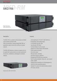
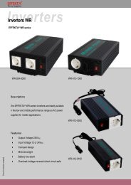
1.2.1. Basis-Konfiguration<br />
Die Basis-Konfiguration besteht aus der<br />
transformerlosen USV im eigenen Gehäuse.<br />
Batterien sind nicht enthalten.<br />
1 - 4 - Allgemeiner Überblick / General overview<br />
DT0344, Betriebsanleitung , Ausgabe 00 - Technical handbook, Issue 00<br />
1.2. CONFIGURATION AND<br />
OPTIONAL EQUIPMENT<br />
1.2.1. Base configuration<br />
Basis-Konfiguration<br />
Base configuration<br />
The base configuration provides trafoless<br />
UPS equipped in its cubicle.<br />
Batteries aren't provided.
UPS 60 -120 kVA<br />
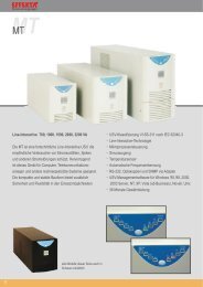
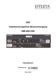
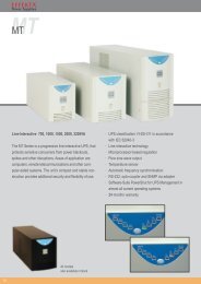
1.2.2. Batterieschrank<br />
Auf Anfrage kann die USV mit Batterien für<br />
die gewünschte Autonomie geliefert werden.<br />
Die Batterien können in einem Gehäuse mit<br />
geeigneten Abmessungen, komplett mit<br />
entsprechenden Trennelementen,<br />
untergebracht werden. Falls die Batteriie nicht<br />
in unmittelbarer Nähe der USV aufgestellt wird,<br />
muss ein geeignetes Trennelement in einem<br />
Wandgehäuse bei der USV vorgesehen werden.<br />
Batterieschrank<br />
Batteries cabinet .<br />
1.2.3. Transformerschrank<br />
Ein Zusatzschrank mit Trenntransformer<br />
für bestimmte Einsatzgebiete, wie z.B.<br />
Spitalanwendungen, ist erhältlich.<br />
Der Standardtransformer ist Tri-phase/Tri-phase<br />
mit einem Übersetzungsverhältnis von 1:1; auf<br />
Anfrage ist auch ein anderes Verhältnis möglich.<br />
Im gleichen Gehäuse kann ein Transformator<br />
zur Reduzierung der netzseitigen<br />
Stromoberwellen untertgebracht werden.<br />
DT0344, Betriebsanleitung , Ausgabe 00 - Technical handbook, Issue 00<br />
1.2.2. Batteries cabinet<br />
UPS can be supplied with a suitable battery<br />
cabinet for the required autonomy . Cabinet<br />
contains also dc isolator to disconnect battery<br />
when necessary.If battery location is not near<br />
the UPS , a wall cabinet containing battery<br />
isolator must be provided near UPS.<br />
USV<br />
UPS<br />
1.2.3. Transformer cabinet<br />
An optional cabinet with a galvanic isolating<br />
transfomer is available and this is specifically<br />
utilized in medical centers.<br />
The standard transformer features a threephase/three-phase<br />
with 1:1 ratio characteristic,<br />
(the transformer ratio can be customized).<br />
In the same cabinet could be equipped a suitable<br />
transformer for line current armonic.<br />
Allgemeiner Überblick / General overview -1- 5<br />
1<br />
ALLGEMEINER ÜBERBLICK - GENERAL OVERVIEW
1<br />
ALLGEMEINER ÜBERBLICK - GENERAL OVERVIEW<br />
UPS 60 -120 kVA<br />
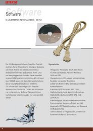
1.2.5. Zubehör - Accessories<br />
UPS MANAGEMENT SOFTWARE<br />
Die Generex Kommunikationssoftware “UPS MANAGEMENT” erlaubt<br />
die Kommunikation zwischen der USV und einem PC oder einem<br />
Netzwerk für die Betriebssysteme Windows, Windows NT, Novell,<br />
OS2, DEC, Linux.<br />
Das Programm überwacht die Betriebsdaten einer oder mehrerer USV-<br />
Anlagen die für die Versorgung eines lokalen Netzwerkes (LAN) von<br />
Personal Computer eingesetzt werden.<br />
The “UPS MANAGEMENT” Generex interaction software : it allows<br />
interaction between UPS and a PC or a PC network based on<br />
Windows, Win-NT, Novel, OS2, Dec, Lynux operation system.<br />
Software controls the operating condition of one or more UPS utilized<br />
to power a local PC network (LAN).<br />
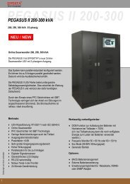
KOMMUNIKATIONS-SCHNITTSTELLENPLATINE<br />
REMOTE INTERACTING CARD<br />
Eine Relaisplatine kann zu der Standard-Platine hinzugefügt werden;<br />
damit ist es möglich zusätzliche Verbindungen mit einem anderen PC<br />
oder mit einem Fernmeldepanel herzustellen; es stehen ebenfalls<br />
Potentialfreie Kontakte auf Klemmen für die Wiederholung der<br />
Zustandsmeldungen der USV zur Verfügung. Hiermit kann jede Art<br />
Vorrichtung angesteuert werden (Summer, Lampen, Fernmeldungen,<br />
usw.).<br />
An relay card can be added to a standard relay card to set up<br />
additional links with another PC or with a remote panel,<br />
this card is also provided with a cold contact tagblock which reverts<br />
the UPS status indications and controls each type of device<br />
(acoustic alarms, lamps, remote indications, etc.).<br />
FERNMELDEPANEL - Remote panel<br />
Mit dem Fernmeldepanel kann der Betriebszustand der USV<br />
überwacht werden und die Alarmmeldungen werden durch LED-<br />
Anzeigen und einem Summer wiederholt. Die Verbindung mit der<br />
USV erfolgt mit einer Klemmenreihe an der Anlagenrückseite.<br />
Remote Panel: it remotely displays the operating mode of UPS, it<br />
reverts the alarms through the lighting up of LEDs and activates a<br />
buzzer. It is connected to UPS through the tagblock on the rear<br />
distribution panel.<br />
1 - 6 - Allgemeiner Überblick / General overview<br />
DT0344, Betriebsanleitung , Ausgabe 00 - Technical handbook, Issue 00<br />
Relaisplatine<br />
Relay card
UPS 60 -120 kVA<br />
1.3. FUNKTIONSPRINZIP<br />
Die USV ist eine On-line USV-Anlage in<br />
Doppelumwandlung mit automatischem Bypass<br />
entsprechend der europäischen Norm<br />
ENV50091-3 (ANIE Definition: Ups CIB). Diese<br />
USV-Type vollzieht, kontinuierlich und<br />
unterbrechungsfrei, eine doppelte Umwandlung<br />
der Eingangsspannung.<br />
Da keine direkte Verbindung zwischen Netz<br />
und Last vorhanden ist, werden keinerlei<br />
Störungen übertragen. Die doppelte<br />
Umwandlung gewährt eine Ausgangsspannung,<br />
die sowohl in Spannung wie in Frequenz dauernd<br />
neu erzeugt wird und ideal für die Versorgung<br />
professioneller Geräte ist.<br />
Wenn die Eingangsspannung sich ausserhalb<br />
der zulässigen Toleranzen befindet, wird die für<br />
die Versorgung der Last notwendige Energie<br />
der Batterie entnommen.<br />
Der Verbraucher profitiert auch vom<br />
automatischen Bypass: bei Ausfall oder Überlast<br />
der USV schaltet der Bypass die Last<br />
unterbrechungsfrei auf Netzversorgung und<br />
stellt so wieder normale Betriebsbedingungen<br />
her.<br />
1.3.1. Eingangsstufe, Leistungsstufe<br />
und Ausgangsstufe<br />
(Bezug: Prinzipschema § 1.3.2.)Von den<br />
Eingangsklemmen gelangt das Netz über den<br />
Schalter MAINS INPUT, zur Leistungsstufe.<br />
Der "step-up converter" sorgt für die AC/DC-<br />
Umwandlung des Netzes (Normalbetrieb) oder<br />
für die DC/DC-Umwandlung der Batterieenergie<br />
bei Netzausfall oder Überschreiten der<br />
zulässigen Toleranzen.<br />
Diese Gleichspannung versorgt den Wechselrichter<br />
der die Wechselspannung neu erzeugt<br />
und die Energieaufnahme entsprechend der<br />
Lastbedürfnissen regelt.<br />
Es folgt der automatische Bypass, ebenfalls<br />
durch die Elektronik gesteuert, der in<br />
Normalbetrieb die durch den Wechselrichter<br />
erzeugte saubere Energie dem Ausgang<br />
zuleitet.<br />
DT0344, Betriebsanleitung , Ausgabe 00 - Technical handbook, Issue 00<br />
1.3. OPERATION<br />
UPS is an On-line type uninterruptible power<br />
unit with double conversion and with automatic<br />
by-pass compliant with the EN50091-1-3 (ANIE<br />
definition: Ups CIB) European Standard.<br />
Since there is no direct mains-load connection<br />
there is no interference, and the double conversion<br />
guarantees a regenerated voltage and<br />
frequency output power always; therefore, it is<br />
ideally employed by professional users.<br />
When the input voltage deviates from the allowed<br />
tolerance, the batteries will give the power<br />
to deliver to the load.<br />
The UPS User also makes use of the automatic<br />
by-pass.<br />
The presence of failure or of overload on the<br />
uninterruptible power unit will cause the bypass<br />
to directly connect the user to mains through<br />
a reserve line, thus restoring the regular operating<br />
conditions without loss of power to the load.<br />
1.3.1. Input Stage, Power Module and<br />
Output Stage<br />
(Reference: Functional drawing 1.3.2)<br />
The mains voltage is delivered by the input<br />
tagblock to the power module through switch<br />
MAINS INPUT.<br />
The step-up converter AC/DC converts mains<br />
(regular operating condition) or DC/DC converts<br />
battery power when mains has either<br />
failed or is not within the set tolerance.<br />
The DC powers the inverter which reconstructs<br />
the AC by adapting the power extracted vs. load<br />
requirements.<br />
An automatic by-pass follows driven by the<br />
control logic. In regular operating conditions it<br />
delivers the power module’s regenerated and<br />
filtered power to the output.<br />
Allgemeiner Überblick / General overview -1- 7<br />
1<br />
ALLGEMEINER ÜBERBLICK - GENERAL OVERVIEW
1<br />
ALLGEMEINER ÜBERBLICK - GENERAL OVERVIEW<br />
UPS 60 -120 kVA<br />
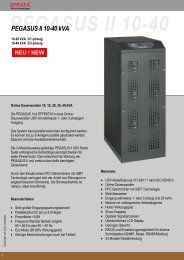
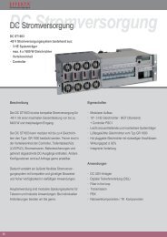
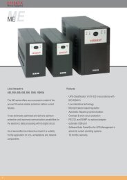
<strong>MANUAL</strong><br />
BY-PASS<br />
RESERVE<br />
INPUT<br />
Netzeingang<br />
mains input<br />
Man. Bypass (Umgehung USV) By-pass line (Ups excluded)<br />
OUTPUT<br />
Aut. Bypass - Automatic by-pass<br />
Automatischer<br />
Bypass<br />
automatic<br />
By-pass<br />
step-up Konverter<br />
step-up converter Inverter<br />
1 - 8 - Allgemeiner Überblick / General overview<br />
DT0344, Betriebsanleitung , Ausgabe 00 - Technical handbook, Issue 00<br />
3PH+N+PE<br />
3PH+N+PE<br />
LEISTUNGSSTUFE<br />
POWER MODULE<br />
MAINS<br />
INPUT<br />
3PH+N+PE<br />
3PH+N+PE<br />
HILFSSPEISUNG<br />
AUX. CONVERTER<br />
HAUPT-STEUERELEKTRONIK<br />
MAIN CONTROL LOGIC<br />
BATT.-LADEGERÄT<br />
BATTERY CHARGER<br />
FRONTPANEL<br />
FRONT PANEL<br />
SCHNITTSTELLE MELDUNGEN<br />
SIGNALLING INTERFACE<br />
USV in Betrieb<br />
Ups run<br />
By-pass ein<br />
By-pass on<br />
400 VAC-Netz vorhanden<br />
400 VAC mains presence<br />
Batterie entladen<br />
Battery low<br />
RELAIS-<br />
PLATINE<br />
RELAYS<br />
BOARD<br />
NOTA - NOTE<br />
Schalter und Relaiskontakte werden<br />
für die ausgeschaltete USV gezeigt.<br />
Switches and relay contacts shown<br />
represent Ups in off state.<br />
zum PC/Fernanzeige<br />
to PC/Remote panel<br />
E.P.O.-Befehl<br />
E.P.O. command<br />
1.3.2. Prinzipschema der USV (Doppelumwandlung mit Bypass)<br />
UPS functional drawing (double conversion/by-pass)
UPS 60 -120 kVA<br />
Wie schon gesagt, bei Ausfall oder Überlast<br />
schaltet der automatische Bypass die Last auf<br />
Netzversorgung um.<br />
Nach Wegfall der auslösenden Ursache, wird<br />
der automatische Bypass wieder auf<br />
Wechselrichterversorgung zurückschalten. Mit<br />
dem Schalter UPS OUTPUT wird die neu<br />
erzeugte saubere 400V Wechselspannung<br />
den Ausgangsklemmen für die Lastversorgung<br />
zugeleitet.<br />
1.3.3. Logik und Hilfskreise<br />
Die Steuer- und Regelelektronik befindet sich<br />
auf einer eigenen Platine und stellt die “intelligente”<br />
Seite der USV-Anlage dar.<br />
Sie steuert und regelt den Betrieb des step-up<br />
Konverters, des Wechselrichters und Bypass in<br />
Funktion der Rückmeldungen der<br />
Leistungsstufe.<br />
Es werden noch drei weitere Platinen verwaltet,<br />
und zwar das Batterieladegerät, die<br />
Hilfsspeisung und die Schnittstelle der<br />
Meldungen.<br />
Das Ladegerät versorgt dauernd die an der<br />
USV angeschlossenen externen Batterie.<br />
Das Gerät kann die Batterie in 12 Stunden bis<br />
80% der Nennkapazität wiederaufladen.<br />
Die Schnittstelle für Meldungen ruft die Signale<br />
der Elektronik ab und konvertiert diese im Format<br />
für Frontpanel und Relaisplatine.<br />
Ebenso werden umgekehrt die Signale vom<br />
Frontpanel (Zwangsumschaltung des aut. Bypass)<br />
und/oder der Relaisplatine (EPO-Befehl)<br />
durch die Meldungsschnittstelle der Elektronik<br />
weitergeleitet, die diese entsprechend als<br />
Schaltbefehl für den aut. Bypass und/oder als<br />
unmittelbarer Abschaltbefeht für die USV<br />
interpretiert.<br />
Die Meldeschnittstelle kann, ausser der Standard-Relaisplatine,<br />
noch eine weitere Zusatz-<br />
Platine (Relais) ansteuern.<br />
Die Hilfsspeisung versorgt die Elektronik, das<br />
Frontpanel sowie die Relaisplatine(n).<br />
DT0344, Betriebsanleitung , Ausgabe 00 - Technical handbook, Issue 00<br />
As already stated, when a faulty or overload<br />
condition arises, the automatic by-pass switches<br />
over to the reserve line. In this manner the load<br />
is still powered from mains.<br />
When the cause that had produced switch-over<br />
clears, the by-pass will automatically revert to<br />
inverter powering.<br />
The 400 Vac filtered, regenerated and stabilized<br />
mains voltage is delivered through the<br />
UPS OUTPUT switch to the load.<br />
1.3.3. Logic and Auxiliary circuits<br />
The control logic resides on a specific card and<br />
represents the “smart” section of UPS. In fact, it<br />
manages the operating mode of the step-up<br />
converter, of the inverter and of the by-pass by<br />
feed-back comparing the signals extracted from<br />
the power module.<br />
The control logic also manages three other<br />
cards, i.e., the battery charger, the auxiliary<br />
power supply unit and the signalling interface.<br />
The battery charger uninterruptedly powers the<br />
batteries connecting UPS.<br />
The battery charger card can recharge up to<br />
80% of the batteries maximum capacity within<br />
12 hours.<br />
The signalling interface extracts signalling from<br />
the control logic and converts them into the<br />
protocol specific for the front panel and for the<br />
Relay card.<br />
Likewise, the criteria inputting from the front<br />
panel (automatic by-pass forcing) and/or from<br />
the Relay card (EPO) are forwarded by the<br />
signalling interface to the control logic where it<br />
will be respectively interpreted, i.e., either switch<br />
over to the reserve line and/or immediately<br />
switching off UPS.<br />
Besides the standard Relay card the signalling<br />
interface can also power an optional card (one<br />
more relay card).<br />
The auxiliary power unit feeds the Control Logic,<br />
the front panel and relay cards.<br />
Allgemeiner Überblick / General overview -1- 9<br />
1<br />
ALLGEMEINER ÜBERBLICK - GENERAL OVERVIEW
1<br />
ALLGEMEINER ÜBERBLICK - GENERAL OVERVIEW<br />
UPS 60 -120 kVA<br />
1.3.4. Batterien<br />
Die Batteriespannung gelangt zum Eingang<br />
des step-up Konverters auf dem<br />
Leistungsmodul. Bei vorhandenem Netz werden<br />
die Batterien kontinuierlich durch das Ladegerät<br />
aufgeladen.<br />
1.3.5. Relais-Platine<br />
Die Relais-platine führt dieselben<br />
Funktionen aus wie die Standardplatine, aber<br />
verfügt zusätzlich noch über potentialfreien<br />
Kontakten auf Klemmen, die die Signale des<br />
Verbinders DB9 wiederholen.<br />
Mit der Relais-Platine ist es also möglich (1) ,<br />
ausser einen PC/eine Fernmeldung, jede Art<br />
Vorrichtung (Summer, Lampen, Fernanzeigen,<br />
usw.) anzusteuern.<br />
(1) : an der Platine kann keine zweite EPO-Taste angeschlossen<br />
werden. Wenn eine Zwangsabschaltung von mehreren EPO-<br />
Tasten aus möglich sein soll, müssen diese in Serie geschaltet<br />
und an einen der CN3-Verbinder angeschlossen werden.<br />
1.3.6. Manueller Bypass<br />
Der manuelle Bypass wird gebraucht um die<br />
USV, ohne Unterbrechung der Lastversorgung,<br />
freizuschalten, wobei die Last vom Netz versorgt<br />
wird (z.B.: USV ausser Betrieb, Ausfall, ...).<br />
Diese Vorrichtung wird mit dem Schalter<br />
<strong>MANUAL</strong> BY-PASS, der sich an der Frontseite<br />
der USV befindet, eingeschaltet. Der Schalter<br />
ist offen bei horizontalem Hebel und hat eine<br />
mechanische Schutz-Blockierung um<br />
unbeabsichtigtes Schalten vorzubeugen. Um<br />
nicht-autorisiertes Personal auszuschliessen,<br />
kann die Blockierung ausserdem mit einem<br />
Hängeschloss gesichert werden.<br />
1.3.7. Frontpanel<br />
Vom Frontpanel kann die USV manuell auf<br />
Bypassbetrieb geschaltet und können Alarmmeldungen<br />
quittiert werden; das Bedienpanel<br />
verfügt über eine Reihe LED zur Anzeige des<br />
Betriebszustandes der USV, der Last sowie<br />
eines jeden Alarmzustandes.<br />
Eine detaillierte Beschreibung des Frontpanels<br />
finden Sie in Kap.4, Betrieb und Wartung.<br />
1 - 10 - Allgemeiner Überblick / General overview<br />
DT0344, Betriebsanleitung , Ausgabe 00 - Technical handbook, Issue 00<br />
1.3.4. Batteries<br />
The power delivered by the batteries reaches<br />
the input of the step-up converter, situated on<br />
the power module. The batteries are continuously<br />
recharged by the battery charger module<br />
when the mains is present.<br />
1.3.5. Relay card<br />
The functions carried out by the relay card are<br />
as those of the standard card except that, with<br />
respect to the latter, it is provided with a cold<br />
contact tagblock which repeats the same signals<br />
of the DB9 plug.<br />
Therefore, the Relay card drives (1) not only a<br />
PC/Remote Panel but also any other type of<br />
device (e.g., acoustic alarms, lamps, remote<br />
indications, etc.).<br />
(1) : The card cannot be connected with an extra EPO button. If<br />
the UPS has to be forced OFF through several EPO buttons,<br />
then these should be series-connected and afterwards connected<br />
to the input port of one of the CN3 plugs.<br />
1.3.6. Manual by-pass<br />
The manual by-pass circuit is utilized in those<br />
circumstances whereby it is necessary to exclude<br />
UPS while still keep load powered from<br />
mains (e.g., Ups not running, failure, etc.). This<br />
circuit can be operated through the <strong>MANUAL</strong><br />
BY-PASS switch located on the rear plane of<br />
UPS. The switch, which is normally open with<br />
the lever set to the orizontal position, is provided<br />
with a protection stopper to prevent it from being<br />
accidentally operated. The stopper can also be<br />
pad-locked to prevent unauthorized personnel<br />
from removing it.<br />
1.3.7. Front panel<br />
The UPS operation is managed through its front<br />
panel. Through it operation can be manually<br />
driven onto the reserve line and the alarm<br />
circuits to be reset. The panel comprises a<br />
complete series of LEDs indicating the operating<br />
state of Ups, the state of the load and any<br />
other alarm state. A thorough description of the<br />
Front Panel is given in chapter 4 “Use and<br />
Maintenance”, to which reference should be<br />
made.
UPS 60 -120 kVA<br />
DT0344, Betriebsanleitung , Ausgabe 00 - Technical handbook, Issue 00<br />
2 - INSTALLATION 2 - INSTALLATION<br />
Inhalt<br />
2.1. Einleitung ...................................... 3<br />
2.1.1.Haftung ................................................ 3<br />
2.1.2.Warenempfang .................................... 4<br />
2.1.3.Produktbestimmung ............................ 4<br />
2.1.4.Auspacken ........................................... 4<br />
2.1.5.Einlagerung ......................................... 6<br />
2.1.6.Aufstellung am Betriebsstandort ......... 7<br />
2.1.7.Elektro-Verteilung der USV ................. 7<br />
2.2. Netzanschluss der USV ................ 8<br />
2.2.1.Vorbereitung des dreiphasigen<br />
Versorgungsnetzes.............................. 9<br />
2.2.2.Klemmen-Anschlüsse ........................ 10<br />
2.2.3.Anschluss der Verbraucher ............... 12<br />
2.3. Anschluss an externe<br />
Vorrichtungen .............................. 14<br />
2.3.1.Anschluss der Taste für die Not-<br />
Ausschaltung (E.P.O.) ....................... 14<br />
2.3.2.Anschluss mit dem PC ...................... 15<br />
2.3.3.Anschluss der Fernmeldung ............. 16<br />
2.4. Relais-Platine (optional) ............. 17<br />
Table of contents<br />
Rev Descrizione Data Controllato Realizzato Data<br />
2.1. Introduction ................................... 3<br />
2.1.1.Limitations of liability............................ 3<br />
2.1.2.Material admittance ............................. 4<br />
2.1.3.Identification ........................................ 4<br />
2.1.4.Packing material removal .................... 4<br />
2.1.5.Storing ................................................. 6<br />
2.1.6.Siting it in the operative position ......... 7<br />
2.1.7.UPS distribution panel ......................... 7<br />
2.2. UPS connection to mains ............ 8<br />
2.2.1.Setting up the three-phase primary<br />
supply mains........................................ 9<br />
2.2.2.Tagblock wiring .................................. 10<br />
2.2.3.User connection................................. 12<br />
2.3. External devices<br />
connection .................................. 14<br />
2.3.1.Emergency Power Off (E.P.O.) pushbutton<br />
connection .............................. 14<br />
2.3.2.Connection to Personal<br />
Computer ........................................... 15<br />
2.3.3.Remote Panel connection ................. 16<br />
2.4. Relay card (optional) .................. 17<br />
U.T.<br />
Approvato<br />
10/10/<br />
2003<br />
Tipo di doc. Pagine n° Pag. totali<br />
Cod.<br />
DT0344-DE00<br />
Installation / Installation 2 - 1<br />
2<br />
INSTALLATION - INSTALLATION
2<br />
INSTALLATION - INSTALLATION<br />
UPS 60 -120 kVA<br />
2.5. Provisorischer Anschluss für die<br />
Wiederaufladung der Batterie .... 18<br />
2.5.1.Prüfungen und Einstellungen ............ 18<br />
2.5.2.Verkabelung....................................... 19<br />
2 - 2 - Installation / Installation<br />
DT0344, Betriebsanleitung , Ausgabe 00 - Technical handbook, Issue 00<br />
2.5. Temporary connection to enable<br />
battery recharge.......................... 18<br />
2.5.1.Tests and setting options................... 18<br />
2.5.2. Wiring................................................ 19
UPS 60 -120 kVA<br />
2.1. EINLEITUNG<br />
Diese Anleitung enthält alle notwendige<br />
mechanische und elektrische Angaben für die<br />
korrekte Installation der USV.<br />
Dieses Kapitel enthält somit die Prozeduren<br />
für richtiges Auspacken, für die Aufstellung<br />
und, anschliessend, Verkabelung und Anschluss<br />
der Anlage.<br />
DIE IN DIESER ANLEITUNG<br />
BESCHRIEBENEN PROZEDUREN DÜRFEN<br />
NUR DURCH ELEKTRIKER ODER<br />
QUALIFIZIERTES TECHNISCHES PERSONAL<br />
DURCHGEFÜHRT WERDEN.<br />
2.1.1. Haftung<br />
Der Hersteller lehnt jede Haft für<br />
Folgeschäden an Sachen oder Personen,<br />
die durch falsche Verbindungen oder nicht<br />
ausdrücklich beschriebene Handlungen<br />
verursacht wurden, vollumfänglich ab.<br />
DT0344, Betriebsanleitung , Ausgabe 00 - Technical handbook, Issue 00<br />
2.1. INTRODUCTION<br />
To properly install UPS all information concerning<br />
its mechanical and electrical interfacing<br />
is supplied inside this manual.<br />
This section reports all the procedures required<br />
to properly unpack the material, to site it<br />
and afterwards to properly wire-connecting it.<br />
ALL THE OPERATIONS DESCRIBED IN THIS<br />
<strong>MANUAL</strong> MUST BE EXECUTED BY AUTHOR-<br />
IZED ELECTRICIANS OR BY QUALIFIED<br />
TECHNICAL PERSONNEL.<br />
2.1.1. Limitations of liability<br />
The constructor shall not be liable for<br />
consequential damages to the equipment or<br />
person based on wrong connections or operations<br />
non specifically set forth.<br />
Installation / Installation 2 - 3<br />
2<br />
INSTALLATION - INSTALLATION
2<br />
INSTALLATION - INSTALLATION<br />
UPS 60 -120 kVA<br />
2.1.2. Warenempfang<br />
Bei der Lieferung überprüfen Sie dass keine<br />
Transportschäden vorliegen; nach sorgfältiger<br />
Prüfung der Verpackung überprüfen Sie den<br />
Inhalt auf einwandfreien Zustand.<br />
Anschliessend kontrollieren Sie dass das<br />
gelieferte Material mit der Beschreibung des<br />
Lieferscheines übereinstimmt.<br />
2.1.3. Produktbestimmung<br />
Die gelieferten Anlagen<br />
sind durch ein selbstklebendes<br />
Typenschild auf der<br />
Anlagenrückseite, dass Modell<br />
und Leistung der USV-Anlage<br />
angibt, gekennzeichnet.<br />
Das Auspacken der<br />
Anlage, d.h. korrektes Entfernen<br />
Transportverpackung<br />
der Anlagen, wird nun im<br />
Folgenden beschrieben.<br />
2.1.4. Auspacken<br />
Beachten Sie hierbei die Angaben auf der<br />
Verpackung (FRAGILE, OBEN), damit eine<br />
Beschädigung der USV-Anlage vermieden wird.<br />
Um die Verpackung zu entfernen, gehen<br />
Sie wie folgt vor (siehe Fig. 2.1):<br />
- Unter Beachtung der Angaben auf der<br />
Verpackung (OBEN, UNTEN), platzieren<br />
Sie die Anlage auf den Fussboden.<br />
- Entfernen Sie Deckel und Seitenteile des<br />
Holzverschlages.<br />
2 - 4 - Installation / Installation<br />
DT0344, Betriebsanleitung , Ausgabe 00 - Technical handbook, Issue 00<br />
Mod.<br />
KVA<br />
In<br />
USV Typenschild - UPS Label<br />
2.1.2. Material admittance<br />
When receiving the material check for damages<br />
that it might have suffered during transportation.<br />
Therefore, properly inspect the packing<br />
case and after having removed the packing<br />
material check that the contents are in perfect<br />
condition.<br />
Afterwards ascertain that the material supplied<br />
is as that reported on the freight bill.<br />
2.1.3. Identification<br />
Imax CE<br />
Out<br />
The equipment supplied is provided with an<br />
adhesive identification label<br />
placed on the UPS rear panel<br />
reporting type of UPS model<br />
and power.<br />
The cases utilized to transport<br />
the equipment must be unpacked<br />
as specified by the procedure<br />
stated below.<br />
2.1.4. Packing material removal<br />
During this operation observe the indications<br />
(FRAGILE, UP) printed on the case to<br />
avoid damaging the UPS.<br />
To remove the packing material proceed in<br />
the following manner (see Fig. 2.1):<br />
- place the equipment on the floor as instructed<br />
on the outer case (UP, DOWN).<br />
- Remove the cover and the side parts of the<br />
wooden crate.
UPS 60 -120 kVA<br />
a) aufrecht auf den Boden stellen, unter<br />
Beachtung der OBEN/UNTEN-Angaben<br />
place it properly on the floor observing the<br />
UP/DOWN indications<br />
c) Polyäthylen-Schutzfolie entfernen.<br />
remove the polyethylene.<br />
DT0344, Betriebsanleitung , Ausgabe 00 - Technical handbook, Issue 00<br />
Fig. 2.1 - Entfernen der Verpackung der USV<br />
Packing removal from UPS<br />
b) Vorsichtig die Verpackungsteile entfernen.<br />
Remuve the board,carefully.<br />
d) mit einem Gabelstapler das Gerät auf den<br />
Boden abstellen<br />
use a forklift truck to place UPS on the floor<br />
Installation / Installation 2 - 5<br />
2<br />
INSTALLATION - INSTALLATION
2<br />
INSTALLATION - INSTALLATION<br />
UPS 60 -120 kVA<br />
- Entfernen Sie die Schutzfolie womit das<br />
Gerät umwickelt ist.<br />
- Mit einem Gabelstapler vorsichtig die USV<br />
von unten aufnehmen, nur wenig anheben<br />
und vorsichtig auf den Boden abstellen. Die<br />
USV ist mit Räder ausgerüstet die ein<br />
müheloses Versetzen erlauben.<br />
- Wir empfehlen das Verpackungsmaterial<br />
aufzuheben; es wird dann von Nutzen sein<br />
wenn die Anlage wieder verpackt werden<br />
muss (z.B.: bei Rückgabe, bei einschicken<br />
an die Servicestelle, bei einem Umzug).<br />
- Vergewissern Sie sich dass das Gerät nicht<br />
beschädigt ist, ansonsten benachrichtigen<br />
Sie sofort den Wiederverkäufer.<br />
2.1.5. Einlagerung<br />
Wenn die Anlage nicht sofort installiert wird,<br />
muss diese an einen feuchte- und<br />
wärmegeschützten Ort eingelagert werden<br />
(zwischen +0 und +40 °C Raumtemperatur und<br />
weniger als 95% RH, nicht kondensierend).<br />
Wenn eine Batterie im Lieferumfang<br />
enthalten ist, stellen Sie ausserdem sicher,<br />
dass bis zur nächsten Batteriewiederaufladung<br />
nicht mehr als 6 Monate<br />
vergehen. Spätestens dann muss die USV<br />
provisorisch angeschlossen und für die<br />
erforderliche Wiederaufladezeit eingeschaltet<br />
werden.<br />
Siehe hierzu Kap. 2.5 - Provisorischer Anschluss<br />
für die Wiederaufladung der Batterie.<br />
2 - 6 - Installation / Installation<br />
DT0344, Betriebsanleitung , Ausgabe 00 - Technical handbook, Issue 00<br />
- Remove the cellophane wrapping utilized<br />
as protection packing.<br />
- Slide the forks of the lift truck under the UPS<br />
and after having lifted it a few centimeters<br />
from the floor, back up and lay it down. UPS<br />
is provided with wheels to easily move it<br />
around.<br />
- Do not throw away the packing material in<br />
that it might be used again to repack the<br />
equipment if having to send it back or to<br />
send it to maintenance centers or for removal<br />
purposes.<br />
- Check that the equipment has not been<br />
damaged. If otherwise immediately contact<br />
the Sales Representative.<br />
2.1.5. Storing<br />
Should the equipment not be installed immediately<br />
it must be stored in a room so as to<br />
protect it against excessive humidity and against<br />
very high heat sources i.e., +5° to +40°C, and<br />
humidity not lower than 95% and moistureless.<br />
If battery cubicle is supplied, make sure that<br />
not more than 6 months pass from the time<br />
the battery had last been recharged.<br />
After such period temporarily connect the UPS<br />
to mains and activate it for the time required to<br />
recharge the batteries.<br />
Refer to para. 2.5 – Temporary connection to<br />
enable battery recharge.
UPS 60 -120 kVA<br />
2.1.6. Aufstellung am Betriebsstandort<br />
Die USV ist mit Räder ausgerüstet und erlauben<br />
einfaches Platzieren am meist geeigneten<br />
Aufstellungsort; dieser gewährt:<br />
- bequemer Anschluss,<br />
- ausreichender Freiplatz für Bedienung und<br />
regelmässige sowie ausserordentliche<br />
Wartungseinsätze,<br />
- ausreichende Belüftung für die Aufnahme<br />
und den Abtransport der USV-Verlustwärme<br />
- Schutz vor Umwelteinflüssen,<br />
- Schutz vor hoher Luftfeuchte oder starken<br />
Wärmequellen,<br />
- Schutz vor Staub,<br />
- Beachtung der gültigen Brandschutz-<br />
Vorschriften,<br />
- Betriebstemperatur zwischen +20 und<br />
+25°C: bei dieser Temperatur haben die<br />
Batterien den höchsten Wirkungsgrad.<br />
2.1.7. Elektroverteilung der USV<br />
Nachfolgend die Anordnung von Schalter und<br />
Anschlüsse.<br />
Externe Anschlüsse<br />
(a) = Anschlussklemmen Eingangsnetz U1-V1-W1-N1<br />
(b) = Anschlussklemmen Bypassversorgung:U3-V3-W3-N3<br />
(c) = Ausgangsklemmen U2-V2-W2-N2<br />
(d) = Erdungsschiene (GND)<br />
(e) = Anschlussklemmen Batterieschrank<br />
(d)<br />
DT0344, Betriebsanleitung , Ausgabe 00 - Technical handbook, Issue 00<br />
2.1.6. Siting it in the operative position<br />
The UPS is fitted with wheels so as to easily<br />
move it to the right place. The place chosen<br />
must guarantee:<br />
- easy connection;<br />
- enough space to easily work on UPS ,<br />
considering also troubleshooting and corrective<br />
maintenance operations;<br />
- interchange of air sufficient enough to dispel<br />
heat produced by UPS;<br />
- protection against atmospheric agents;<br />
- protection against excessive humidity and<br />
very high heat sources;<br />
- protection against dust;<br />
- compliance with the current fire prevention<br />
norms.<br />
- operative environment temperature within<br />
+20° C and +25° C. The batteries are at<br />
maximum efficiency in this temperature<br />
range.<br />
2.1.7. UPS distribution panel<br />
The following figure illustrates the switches and<br />
plugs arranged on UPS.<br />
(1) (2) (3) (4)<br />
(a) (b) (c)<br />
(6)<br />
(5)<br />
External connections<br />
(a) = Input mains terminal blocks U1-V1-W1-N1<br />
(b) = Reserve line terminal blocks U3-V3-W3-N3<br />
(c) = Output terminal blocks U2-V2-W2-N2<br />
(d) = GND busbar<br />
(d) = Ext. Battery terminal blocks<br />
(e)<br />
Gerätebezeichnungen<br />
(1) = Eingangsnetzschalter<br />
(2) = Eingangsschalter Bypassversorgung<br />
(3) = Schalter für den manuellen Bypass<br />
(4) = Ausgangsschalter (zur Last)<br />
(5) = Erdungsschiene<br />
(6) = Batterie-Sicherungstrenner<br />
Devices description<br />
(1) = Input mains MCB<br />
(2) = ReserveInput MCB<br />
(3) = Manual By-pass MCB<br />
(4) = UPS Output MCB (to load)<br />
(5) = GND bar<br />
(6) = Battery fuses<br />
Installation / Installation 2 - 7<br />
2<br />
INSTALLATION - INSTALLATION
2<br />
INSTALLATION - INSTALLATION<br />
UPS 60 -120 kVA<br />
2.2. NETZANSCHLUSS DER USV<br />
Zur gewährung eines korrekten Betriebes<br />
der USV samt Zusatzeinrichtungen, müssen<br />
geeignete Schutzeinrichtungen sowohl in der<br />
Versorgungsleitung wie in der Lastleitung<br />
vorgesehen werden.<br />
Die zu erstellenden Verbindungen werden<br />
in Fig. 2.2 schematisch angezeigt.<br />
DIE IM FOLGENDEN BESCHRIEBENEN AR-<br />
BEITEN DÜRFEN NUR DURCH ELEKTRIKER<br />
ODER QUALIFIZIERTES TECHNISCHES PER-<br />
SONAL DURCHGEFÜHRT WERDEN.<br />
Netz 380÷415VAC/50 Hz 3P+N+PE (GND)<br />
mains 380÷415 Vac/50 Hz 3ph+N+PE (GND)<br />
2 - 8 - Installation / Installation<br />
DT0344, Betriebsanleitung , Ausgabe 00 - Technical handbook, Issue 00<br />
Thermo-magnetischer Schalter (1) “Kurve C”<br />
Magnetothermic switch (1) “Curve C”<br />
USV Bypass-Schalter (normalerweise offen)<br />
UPS By-pass switch (normally open)<br />
UPS<br />
Thermo-magnetischer Schalter (1) “KurveC”<br />
Magnetothermic switch “Curve C”<br />
(1) = Vierpoliger Thermo-magnetischer Differentialschalter für pulsierenden Wechselstrom mit Gleichstromanteil,<br />
gekennzeichnet durch die Symbole . Die minimale Schaltschwelle muss 500 mA betragen.<br />
a.c. four-pole safety magnetothermic switch, push-button with dc component,<br />
distinguished by symbol . The minimum time to intervene must be 500 mA.<br />
Fig. 2.2 - Prinzipschema der Installation für die USV<br />
UPS installation schematic<br />
2.2. UPS CONNECTION TO MAINS<br />
To guarantee that the UPS and relative<br />
optional equipment operate properly a mains<br />
point must be provided both at the input and<br />
output of the equipment which must also be<br />
provided with the specific protection devices.<br />
The wiring connections to be executed are<br />
shown in Fig. 2.2<br />
THE OPERATIONS DESCRIBED IN THE FOL-<br />
LOWING PARAGRAPHS MUST BE CAR-<br />
RIED OUT BY AUTHORIZED ELECTRICIANS<br />
OR BY TECHNICAL PERSONNEL.<br />
zum Verbraucher -<br />
To users
UPS 60 -120 kVA<br />
2.2.1. Vorbereitung des dreiphasigen<br />
Versorgungsnetzes<br />
Vor Anschlusss der USV kontrollieren Sie<br />
dass:<br />
- die Netzdaten (Spannung und Frequenz)<br />
mit den Daten des Leistungsschildes an der<br />
USV-Rückseite übereinstimmen<br />
(Eingangsspannung und -frequenz);<br />
- die Anlagenerdung genau entsprechend<br />
den IEC- oder gültigen örtlichen Vorschriften<br />
erstellt wurde.<br />
Anschliessend installieren Sie eingangsund<br />
ausgangsseitig die vierpoligen thermomagnetischen<br />
Schalter (siehe Fig. 2.2) mit<br />
folgenden Daten:<br />
- Leistung gleich oder grösser als die auf<br />
dem Leistungsschild der USV angegebene<br />
Leistung (KVA);<br />
- Auslöse-Karakteristik entsprechend CEI-<br />
Normen oder gültigen örtlichen Vorschriften<br />
für thermo-magn. Schalter “Kurve C”.<br />
- Die Verbindungsleitungen müssen<br />
ausreichende Überlänge aufweisen, damit<br />
die USV, für seitliche und rückseitige<br />
Zugänglichkeit bei Wartungsarbeiten, um<br />
mindestens 80cm verschoben werden kann.<br />
DT0344, Betriebsanleitung , Ausgabe 00 - Technical handbook, Issue 00<br />
2.2.1. Setting up the three-phase primary<br />
supply mains<br />
Before connecting the UPS check that:<br />
- the mains voltage and frequency values are<br />
as those indicated on the adhesive label<br />
attached on the rear plane of the UPS (input<br />
voltage, working frequency);<br />
- plant grounding fully complies either with<br />
IEC norms or local laws.<br />
Afterwards, start installing the four-pole<br />
magnetothermic switches both at the input and<br />
output of the UPS (see Fig. 2.2). The switches<br />
feature:<br />
- capacity equal or greater than that reported<br />
on the label situated on the UPS rear plane<br />
(KVA);<br />
- characteristics compliant either with IEC<br />
norms or local laws for “Curve C”<br />
magnetothermic switches.<br />
- Connecing cables must have a suitable<br />
lenght to allow the cubicle to advance at<br />
least 80cm, for lateral and back accessibility<br />
in case of mantainance.<br />
Installation / Installation 2 - 9<br />
2<br />
INSTALLATION - INSTALLATION
2<br />
INSTALLATION - INSTALLATION<br />
UPS 60 -120 kVA<br />
2.2.2. Klemmenanschlüsse<br />
DIE BESCHRIEBENEN ARBEITEN DÜRFEN<br />
NUR DURCH ELEKTRIKER ODER<br />
QUALIFIZIERTES TECHNISCHES PERSO-<br />
NAL DURCHGEFÜHRT WERDEN.<br />
Für alle Verbindungen Kabelquerschnitte<br />
gemäss Tabelle auf Seite 2-9 verwenden.<br />
Für die Sicherheit des installierenden<br />
Personals stellen Sie sicher dass für die<br />
Anschlussarbeiten folgende Bedingungen<br />
gewährleistet sind:<br />
- Netzversorgungsspannung abgeschaltet;<br />
- Verbraucher ausgeschaltet;<br />
- USV vollständig ausgeschaltet.<br />
Um die USV vollständig auszuschalten:<br />
a) die Schalter für Netzeingang (1),<br />
Reserveleitung (2) und Ausgang (4) öffnen,<br />
b) Batteriesicherungstrenner (5) öffnen<br />
c) BYPASS-Schalter (3) öffnen.<br />
1) Türe öffnen und die untere<br />
Schutzabdeckung entfernen.<br />
2) Die Erdleitung von der Hauptverteilung<br />
an der Erdungsschiene anschliessen.<br />
2 - 10 - Installation / Installation<br />
DT0344, Betriebsanleitung , Ausgabe 00 - Technical handbook, Issue 00<br />
2.2.2. Tagblock wiring<br />
(1) (2) (3)<br />
(4)<br />
THE OPERATIONS DESCRIBED IN THE<br />
PARAGRAPHS THAT FOLLOW MUST BE<br />
CARRIED OUT BY AUTHORIZED ELECTRI-<br />
CIANS OR BY TECHNICAL PERSONNEL.<br />
Use section cables as described in page 2-9.<br />
As far as the installation personnel’s<br />
safety is concerned, make sure that the wiring<br />
operations are carried out under the following<br />
conditions:<br />
- primary mains voltage cut off;<br />
- users cut-off;<br />
- UPS fully de-activated.<br />
To fully deactivate the UPS:<br />
a) open the main power switch (1),the reserve<br />
line switch (2), the output switch (4) by<br />
setting the lever to the down position<br />
b) open the battery switch (5) by setting the<br />
lever to the down position;<br />
c) open the BY-PASS switch (3) by setting the<br />
lever it to the down position.<br />
1) Open the door and remove the lower<br />
protection panel<br />
2) Connect the ground lead, incoming from<br />
the main distribution panel, to the GND<br />
busbar of the cubicle.<br />
(5)
UPS 60 -120 kVA<br />
3) Der Schutzleiter der Lastversorgung an<br />
die Erdungsschiene der USV<br />
anschliessen.<br />
4) Die Kabel des Eingangsnetzes,<br />
entsprechend Bild unten, an den<br />
Klemmen des Schalters I1 anschliessen.<br />
5) Die Kabel der Lastversorgung an den<br />
Klemmen des Schalters I4 anschliessen.<br />
6) Die Kabel der Res.-Versorgung an den<br />
Klemmen des Schalters I3 anschliessen.<br />
7) Die Kabel des Batterieschrankes an den<br />
Klemmen der Trennsicherungen<br />
anschliessen.<br />
Die empfohlene Kabel-<br />
Querschnitte werden in<br />
der Tabelle auf Seite 2-9<br />
angegeben.<br />
Die Bezugsnormen für<br />
Kabeldimensionierung<br />
sind: VDE 0100 Teil 3 und<br />
UNEL 35024170<br />
Use section cables as<br />
described in the table of<br />
pag.2-9.The reference<br />
norms adopted for the<br />
dimensions of the<br />
cables are: VDE 0100<br />
part 3 and<br />
UNEL 35024170<br />
Verbraucher-Schutzleiter<br />
Ground lead towards users<br />
1 = Netzeingang Phase U1 Input phase<br />
2 = Netzeingang Phase V1 Input phase<br />
3 = Netzeingang Phase W1Input phase<br />
4 = Netzeingang Nullleiter Input neutral<br />
5 = Res.-Eingang Phase U1Input reserve<br />
6 = Res.-Eingang Phase V1Input reserve<br />
7 = Res.-Eingang Phase W1Input reserve<br />
8 = Res.-Eingang Nullleiter Input neutral<br />
DT0344, Betriebsanleitung , Ausgabe 00 - Technical handbook, Issue 00<br />
ANSCHLUSSKLEMMEN DER USV<br />
UPS TAGBLOCK<br />
1 2 3 4 5 6 7 8<br />
(U1) (V1) (W1) (N1) (U3) (V3) (W3) (N3)<br />
Erdung<br />
Ground<br />
Netzeingang<br />
Mains input<br />
Eingang Reservenetz<br />
reserve input<br />
9 = Pluspol Batterie Battery positive<br />
10 = Minuspol Batterie Battery negative<br />
11 = Ausgang Phase U2 Output phase<br />
12 = Ausgang Phase V2 Output phase<br />
13 = Ausgang Phase W2 Output phase<br />
14 = Ausgang Nullleiter Output neutral<br />
15 = Schutzerdung GND Ground<br />
Fig. 2.3 - Anschlüsse an den Klemmen der USV<br />
Wiring on the UPS tagblock<br />
3) Connect ground for utilities to the<br />
UPS GND busbar .<br />
4)Connect mains cables to isolator<br />
I1terminal blocks , as indicated on figure.<br />
5) Connect load cables to isolator I4<br />
terminal blocks.<br />
6) Connect reserve mains cables to<br />
isolator I3 terminal bloks<br />
7)Connect cables from battery cubicle to<br />
isolating fuses terminals<br />
(15)<br />
9 10<br />
(+) (-)<br />
Batterie-Eingang<br />
battery input<br />
11 12 13 14<br />
(U2) (V2) (W2) (N2)<br />
USV Ausgang<br />
UPS output<br />
an dieser Schiene den<br />
Schutzleiter der USV-Netz-<br />
Einspeisung anschliessen<br />
Onto this terminal connect<br />
the ground lead incoming<br />
from the UPS input mains<br />
power supply<br />
Installation / Installation 2 - 11<br />
2<br />
INSTALLATION - INSTALLATION
2<br />
INSTALLATION - INSTALLATION<br />
UPS 60 -120 kVA<br />
2.2.3. Anschluss der Verbraucher<br />
Es wird empfohlen am Ausgang der USV ein<br />
vierpoliger thermo-magnetischer Schalter “Kurve<br />
C” vorzusehen (siehe Fig. 2.2 und 2.4).<br />
DIE BESCHRIEBENEN ARBEITEN DÜRFEN<br />
NUR DURCH ELEKTRIKER ODER<br />
QUALIFIZIERTES TECHNISCHES PERSO-<br />
NAL DURCHGEFÜHRT WERDEN.<br />
Für die Anschlussarbeiten müssen folgende<br />
Bedingungen gewährleistet sein:<br />
- Netzversorgungsspannung abgeschaltet;<br />
- Verbraucher ausgeschaltet;<br />
- USV vollständig ausgeschaltet.<br />
Durch Befestigender Kabel an der<br />
Zugentlastungsschiene unterhalb<br />
der Schalter werden diese an der<br />
USV verankert.<br />
The bar near the switch blocks can be<br />
used to fasten the cable to the UPS<br />
through cable clamps.<br />
2 - 12 - Installation / Installation<br />
DT0344, Betriebsanleitung , Ausgabe 00 - Technical handbook, Issue 00<br />
VERBRAUCHER1 -<br />
<strong>USER</strong> 1<br />
4-poliger thermo-magn. Fi-<br />
Schalter “Kurve C”<br />
four-pole “Curve C”<br />
magnetothermic switch<br />
Steckdose<br />
Verbr. 1<br />
User<br />
socket 1<br />
2.2.3. User connection<br />
Its suggested to connect a four-pole “Curve C”<br />
magnetothermic switch at the output of the UPS<br />
(see Fig. 2.2 and Fig. 2.4).<br />
THE OPERATIONS DESCRIBED IN THE<br />
PARAGRAPHS THAT FOLLOW MUST BE<br />
CARRIED OUT BY AUTHORIZED ELECTRI-<br />
CIANS OR BY TECHNICAL PERSONNEL.<br />
The wiring operations must be carried out under<br />
the following conditions:<br />
- primary mains voltage cut off;<br />
- users cut-off;<br />
- UPS fully de-activated.<br />
thermo-magn.<br />
Fi-Schalter 1<br />
safety<br />
magnetothermic 1<br />
Steckdose<br />
Verbr. 2<br />
User<br />
socket 2<br />
VERBRAUCHER2 -<br />
<strong>USER</strong> 2<br />
Fig. 2.4 - Ausgangsverteilung Verbraucher<br />
Load distribution Panel<br />
VERBRAUCHERANSCHLUSS-VERTEILUNG<br />
LOAD DISTRIBUTION PANEL<br />
thermo-magn.<br />
Fi-Schalter 2<br />
safety<br />
magnetothermic 2<br />
Steckdose<br />
Verbr. n<br />
User<br />
socket n<br />
thermo-magn.<br />
Fi-Schalter ...n<br />
safety<br />
magnetothermic ..n<br />
VERBRAUCHER-n /<br />
<strong>USER</strong>-n
UPS 60 -120 kVA<br />
- Das Kabel der Lastversorgung an den<br />
Klemmen “15” (Erde), “11-12-13” (Phase)<br />
und “14” (Nullleiter) des thermo-magn.<br />
Fi-Schalters “KurveC” in der<br />
“Verbraucher-Verteilung” anschliessen.<br />
Die Ausgänge des Schalters “Kurve C” müssen<br />
Parallel an den Verbraucher-Steckdosen<br />
verdrahtet werden; wir empfehlen diese<br />
Verbindungen ebenfalls mit thermo-magn. Fi-<br />
Schaltern auszuführen, je ein Schalter pro<br />
Steckdose: die Schalter erlauben es, wenn<br />
notwendig, die einzelnen Verbraucher<br />
freizuschalten.<br />
Die Daten der vor den Verbrauchern zu<br />
installierenden Schalter, sowie die betr.<br />
Kabelquerschnitte, sind abhängig von der<br />
vorgesehenen jeweiligen Belastung.<br />
Nach beenden der Anschlussarbeiten muss<br />
die Schutzabdeckung der Anschlussklemmen<br />
wieder angebracht werden.<br />
Anschliessend stellen Sie die USV an der<br />
geeignetsten Stelle auf.<br />
DT0344, Betriebsanleitung , Ausgabe 00 - Technical handbook, Issue 00<br />
- Connect the UPS output cable to terminals<br />
“15” (ground), “11-12-13” (phase)<br />
and “14” (neutral) of the “Curve C”<br />
magnetothermic switch on the “User Distribution<br />
Panel”.<br />
Outputs of the “Curve C” switch must be parallelconnected<br />
to the user sockets; it is suggested to<br />
set up this link using other safety magnetothermic<br />
switches, one per socket: the magnetothermic<br />
switches will, if necessary, isolate each single<br />
user.<br />
The characteristics of the magnetothermic<br />
switches, to insert at the user input, and the<br />
cable sections are based on the loads applied to<br />
the various sockets.<br />
At the end of every connection, assembly again<br />
the protection panel on the UPS tagblock.<br />
Place UPS into the position considered most<br />
fitting for the use .<br />
Installation / Installation 2 - 13<br />
2<br />
INSTALLATION - INSTALLATION
2<br />
INSTALLATION - INSTALLATION<br />
UPS 60 -120 kVA<br />
2.3. ANSCHLUSS AN EXTERNE<br />
VORRICHTUNGEN<br />
An der Rückseite der USV befindet sich der<br />
Zugang zu einer Relais-Platine für den Anschluss<br />
einer externen Not-Aus-Taste (E.P.O.=<br />
Emergency Power Off).<br />
Ausserdem befindet sich darauf auch einen DB9-<br />
Verbinder womit die USV mit einem PC verbunden<br />
werden kann.<br />
Eine Klemmleiste auf der Platine erlaubt es, die<br />
USV mit einer Fernmeldung zur Fern-Anzeige<br />
der Betriebszustände zu verbinden.<br />
2.3.1. Anschluss der Taste für die Not-<br />
Ausschaltung (E.P.O.)<br />
1) Das zwei-polige Verbindungskabel (Leiter-<br />
Querschnitt 0,6 mm 2 ) darf nicht länger als<br />
100 m sein.<br />
2) Das Kabel mit einem Öffner-Kontakt (NC)<br />
einer Pilztaste verbinden (Fig. 2.5).<br />
3) Das andere Ende des Kabels mit der Relais-<br />
Platine verbinden (Fig. 2.5).<br />
NOTA: die USV kann mit einer weiteren Relais-Platine (optional)<br />
ausgerüstet werden und somit sowohl mit einer Fernmeldung wie<br />
einem PC verbunden werden. Es ist hingegen nicht möglich an<br />
dieser Karte eine zweite EPO-Taste anzuschliessen. Mehrere<br />
EPO-Tasten müssen seriegeschaltet werden und an einen der<br />
vorhandenen CN3-Verbinder angeschlossen werden.<br />
○ ○ ○ ○ ○ ○ ○ ○ ○ ○ ○ ○ ○<br />
2 - 14 - Installation / Installation<br />
DT0344, Betriebsanleitung , Ausgabe 00 - Technical handbook, Issue 00<br />
Relais-Platine<br />
relay-card<br />
2.3. EXTERNAL DEVICES CON-<br />
NECTION<br />
A Relay card is situated on UPS rear panel.<br />
Through this card UPS is connected to a<br />
pushbutton whose function is of forcing UPS<br />
OFF should an emergency condition arise (E.P.O.<br />
= Emergency Power Off).<br />
Through plug DB9 the card can establish connection<br />
with UPS to a Personal Computer.<br />
Throught tag-block on it is possible to connect<br />
UPS to a remote panel for UPS status indications.<br />
2.3.1. Emergency Power Off (E.P.O.)<br />
push-button connection<br />
1) Get a suitably long (not more than 100 m.)<br />
two-pole cable (0.6sq.mm conductor section)<br />
2) Terminate one end of the cable to the N.C.<br />
pins of a fire preventing button (Fig. 2.5).<br />
3) connect the other end of the cable to<br />
Relay card (Fig. 2.5).<br />
NOTE: Another Relè card (optional) can be mounted on UPS<br />
hence connecting it both to the remote panel and to the PC. The<br />
card cannot be fitted with an additional EPO button. To connect<br />
several EPO buttons to UPS first connect them in series and then<br />
connect the lot to one of the CN3s available.<br />
N.C.= Öffner-Kontakt<br />
Normally Closed<br />
Fig. 2.5 - Anschluss der E.P.O.-Taste - E.P.O. connection<br />
E.P.O.-Taste<br />
E.P.O. pushbutton
UPS 60 -120 kVA<br />
2.3.2. Anschluss mit dem PC<br />
Die Signalschnittstelle der Zephyr erlaubt<br />
die Überwachung des Betriebszustandes der<br />
USV mittels PC. Sobald sich Fehlzustände<br />
einstellen, werden diese detailliert auf dem PC-<br />
Bildschirm dargestellt.<br />
Für die Verbindung verwenden Sie bitte<br />
ausschliesslich das im Lieferumfang der<br />
Generex-Software enthaltene Spezialkabel. Die<br />
Software mit Zubehör wird auf Verlangen als<br />
Optional geliefert.<br />
1) Das Steckerende des Kabels mit dem<br />
entspechenden DB9-F Verbinder der USV<br />
und das andere Ende gemäss nachfolgender<br />
Skizze mit einem seriellen Anschluss des<br />
PC verbinden.<br />
DT0344, Betriebsanleitung , Ausgabe 00 - Technical handbook, Issue 00<br />
DB9-F<br />
Verbinder<br />
DB9 female<br />
connector<br />
2) Einrichten der Einstellungen wie im Kap.<br />
4.2.4, Voreinstellungen, beschrieben.<br />
2.3.2. Connection to Personal Computer<br />
The signals interface equipping UPS monitors<br />
the state of UPS with the Personal Computer.<br />
Any failures present will be fully displayed on<br />
the PC.<br />
To set up this connection use the cable<br />
supplied with the Generex software. The software<br />
together with the relative kit are optionally<br />
supplied on Customer demand.<br />
1) Connect the male connector tipped end to<br />
the corresponding DB9 female connector<br />
on UPS and the other end to a serial port on<br />
the PC as shown below.<br />
zum seriellen PC-<br />
Anschluss<br />
To the PC serial port<br />
2) Preset as specified at para. 4.2.4 in the Setup<br />
chapter.<br />
Installation / Installation 2 - 15<br />
2<br />
INSTALLATION - INSTALLATION
2<br />
INSTALLATION - INSTALLATION<br />
UPS 60 -120 kVA<br />
2.3.3. Anschluss der Fernmeldung<br />
Das Fernmeldepanel ist mit einer Speisung<br />
ausgerüstet.<br />
Erstellen Sie ein Kabel geeigneter Länge, bis zu<br />
max. 100 m, entsprechend der Skizze Fig. 2.6.<br />
Klemmleiste (USV-seitig)<br />
Tagblock (UPS side)<br />
1<br />
2<br />
2 - 16 - Installation / Installation<br />
4<br />
9<br />
12<br />
Morsettiera M1<br />
M1 Tag-block<br />
DT0344, Betriebsanleitung , Ausgabe 00 - Technical handbook, Issue 00<br />
Querschnitt 0,6 mm 2 , L max. = 100 m<br />
0.6 sq.mm. section max. L. = 100 m.<br />
Batterie entladen - Low battery<br />
Gem. Rückleitung - Common<br />
Netz vorhanden - mains ON<br />
Bypass EIN - By pass ON<br />
USV in Betrieb - UPS ON<br />
2.3.3. Remote Panel connection<br />
The remote signalling panel is provided with a<br />
power supply unit.<br />
Proceed to assemble a connecting cable up but<br />
not longer than 100m as shown in Figure 2.6.<br />
LOW BATTERY<br />
ON BYPASS<br />
ALARM SILENCE<br />
POWER ON<br />
Fig. 2.6 - Verdrahtungsschema Verbindungskabel Fernmeldung<br />
Drawing showing Remote Panel wiring cable<br />
Klemmleiste (USV-seitig)<br />
Tagblock (panel side)<br />
1<br />
5<br />
4<br />
3<br />
2
UPS 60 -120 kVA<br />
2.4. RELAISPLATINE(OPTIONAL)<br />
Auf Anfrage kann eine weitere Relaisplatine als<br />
Erweiterung der Standard-Platinegeliefert<br />
werden. (1).<br />
1) Erstellen Sie die Verbindungen gemäss<br />
Schema der Fig. 2.7.<br />
2) Führen Sie die Jumper-Voreinstellung wie<br />
im Kap. 3 beschrieben, aus.<br />
(1) : Es ist nicht möglich an dieser Relaisplatine eine zweite EPO-<br />
Taste anzuschliessen. Wenn mehrere EPO-Tasten angeschlossen<br />
werden müssen, müssen diese seriegeschaltet werden und an<br />
einen der vorhandenen CN3-Verbinder angeschlossen werden.<br />
Klemmen für den E.P.O.-<br />
Anschluss (siehe Fig. 2.5)<br />
E.P.O. wiring terminals (see<br />
Fig. 2.5)<br />
DB9-Verbinder für den<br />
Anschluss an einem PC<br />
(siehe Kap. 2.3.2)<br />
DB9 plug for Personal<br />
Computer connection (see<br />
para. 2.3.2)<br />
DT0344, Betriebsanleitung , Ausgabe 00 - Technical handbook, Issue 00<br />
Klemmen für Anschluss der USV<br />
UPS connection tagblock<br />
2.4. RELAY CARD (OPTIONAL)<br />
A Relay card is supplied upon customer demand.<br />
This card can be added to the Relè one (1) .<br />
1) Proceed to wire-connect as shown on the<br />
diagram of Fig. 2.7.<br />
2) Strap preset as reported in the Set up chapter<br />
(1) : The Relay card cannot be fitted with an additional EPO<br />
button. To connect several EPO buttons to UPS first connect<br />
them in series and then connect the lot to one of the CN3s<br />
available.<br />
N.O.<br />
COM.<br />
N.C.<br />
N.O.<br />
COM.<br />
N.C.<br />
N.O.<br />
COM.<br />
N.C.<br />
N.O.<br />
COM.<br />
N.C.<br />
Fig. 2.7 - Anschlussschema der Schnittstelle Relaisplatine<br />
Signals interface with relay card wiring diagram<br />
Klemmen für die potentialfreien<br />
Kontakten, zur freien Kundenverwendung<br />
(Anschluss einer<br />
Fernmeldung siehe Kap. 2.3.3)<br />
Tagblock with cold contacts free<br />
for the User (Remote Panel<br />
connection see para. 2.3.3)<br />
USV IN BETRIEB<br />
UPS RUNNING<br />
BY- PASS INSERITO<br />
BY-PASS ON<br />
NETZ VORHANDEN<br />
MAINS PRESENCE<br />
BATTERIE ENTLADEN<br />
BATTERY FLAT<br />
Legende - Legend:<br />
N.O. = Schliesser - Normally open<br />
COM.= Gemeinsam - Common<br />
N.C. = Öffner - Normally Closed<br />
Installation / Installation 2 - 17<br />
2<br />
INSTALLATION - INSTALLATION
2<br />
INSTALLATION - INSTALLATION<br />
UPS 60 -120 kVA<br />
2.5. PROV. ANSCHLUSS FÜR DIE<br />
WIEDERAUFLADUNG DER<br />
BATTERIE<br />
DIE IM FOLGENDEN BESCHRIEBENEN AR-<br />
BEITEN DÜRFEN NUR DURCH ELEKTRIKE<br />
ODER QUALIFIZIERTES TECHNISCHES<br />
PERSONAL DURCHGEFÜHRT WERDEN.<br />
2.5.1. Prüfungen und Einstellungen<br />
Sie:<br />
Bevor Sie die USV anschliessen, prüfen<br />
1) Netzspannung und Frequenz: diese müssen<br />
mit den Angaben auf dem Typenschild auf<br />
der Rückseite der USV übereinstimmen<br />
(Eingangsspannung und Frequenz);<br />
2) die Leistung des thermo-magn. Schalters:<br />
diese muss gleich oder grösser als die<br />
Angabe auf dem USV-Typenschild sein<br />
(kVA);<br />
3) die Erdung der Anlage: diese muss den IEC-<br />
Normen oder den örtlichen Vorschriften völlig<br />
entsprechen.<br />
Für die Sicherheit des installierenden<br />
Personals prüfen Sie dass für die<br />
Anschlussarbeiten folgende Bedingungen<br />
gewährleistet sind:<br />
- Netzversorgungsspannung abgeschaltet;<br />
- USV vollständig ausgeschaltet.<br />
Um die USV vollständig auszuschalten:<br />
a) Hauptschalter (1), Reserveleitung (2) und<br />
Ausgangsschalter (4) öffnen (Schalthebel<br />
Horizontal);<br />
2 - 18 - Installation / Installation<br />
DT0344, Betriebsanleitung , Ausgabe 00 - Technical handbook, Issue 00<br />
2.5. TEMPORARY CONNECTION<br />
TO ENABLE BATTERY RE-<br />
CHARGE<br />
THE OPERATIONS DESCRIBED IN THE<br />
PARAGRAPHS THAT FOLLOW MUST BE<br />
CARRIED OUT BY AUTHORIZED ELECTRI-<br />
CIANS OR BY TECHNICAL PERSONNEL.<br />
2.5.1. Tests and setting options<br />
Before wire-connecting the UPS, check:<br />
1) the mains voltage and frequency values:<br />
these must correspond to those<br />
indicated on the adhesive label attached on<br />
the rear plane of the UPS (input voltage,<br />
working frequency);<br />
2) magnetothermic switch capacity: must be<br />
equal or greater than that reported on the<br />
label situated on the UPS rear plane (KVA);<br />
3) plant grounding: must fully comply either<br />
with IEC norms or local laws.<br />
As far as the installation personnel’s<br />
safety is concerned, make sure that the wiring<br />
operations are carried out under the following<br />
conditions:<br />
- primary mains voltage cut off;<br />
- UPS fully de-activated.<br />
To fully deactivate the UPS:<br />
a) open the main power switch (1),the reserve<br />
line switch (2), the output switch (4) by setting<br />
the lever to the horizontal position
UPS 60 -120 kVA<br />
b) Batteriesicherungstrenner (5) öffnen(OFF)<br />
(Schalthebel horizontal);<br />
c) BYPASS-Schalter (3) öffnen (OFF),<br />
(Schalthebel horizontal);<br />
2.5.2. Verkabelung<br />
1) Die vier Befestigungsschrauben des<br />
Schutzbleches der Anschlussklemmen der<br />
USV vollständig lösen.<br />
2) Die Schutzerde an die Erdungsschiene “15”<br />
der USV befestigen (fig. 2.8).<br />
Für die Erdung verwenden Sie ein Kabel von<br />
mindestens 6 mm 2 Querschnitt.<br />
3) Das Kabel der Netzzuleitung (Fig. 2.8) an<br />
den Klemmen der USV anschliessen:<br />
2 = Phase U1<br />
3 = Phase V1<br />
4 = Phase W1<br />
5 = Nullleiter N1<br />
Für den Netzanschluss verwenden Sie Leiter<br />
von mindestens 6 mm 2 Querschnitt.<br />
Nachdem der Anschluss erstellt wurde,<br />
führen Sie die Wiederaufladung der Batterie<br />
entsprechend den Angaben im Kapitel BETRIEB<br />
UND WARTUNG durch.<br />
DT0344, Betriebsanleitung , Ausgabe 00 - Technical handbook, Issue 00<br />
(1) (2) (3)<br />
(4)<br />
b) open the battery switch (5) by setting the<br />
lever to the down position;<br />
c) open the BY-PASS switch (3) by setting the<br />
lever it to the down position.<br />
(5)<br />
2.5.2. Wiring<br />
1) Fully unscrew the four screws from the protection<br />
panel situated on the UPS tagblock.<br />
2) Connect the ground lead to the “PE” bar of<br />
the UPS (Fig. 2.8).<br />
To ground connect use a 6 sq.mm. section<br />
cable.<br />
3) Connect the mains voltage lead (see Fig.<br />
2.8) to the following UPS terminals:<br />
1 = phase U1<br />
2 = phase V1<br />
3 = phase W1<br />
4 = neutral N1<br />
With regard to mains voltage connection use a 6<br />
sq.mm. section cable.<br />
After having completed the wiring connections<br />
charge the batteries as instructed in the<br />
<strong>USER</strong> <strong>MANUAL</strong> chapter.<br />
Installation / Installation 2 - 19<br />
2<br />
INSTALLATION - INSTALLATION
2<br />
INSTALLATION - INSTALLATION<br />
UPS 60 -120 kVA<br />
Netz 380÷415VAC/50 Hz - 3Ph+N+PE (GND)<br />
mains 380÷415 Vac/50 Hz 3PH+N+PE (GND)<br />
(A) (B)<br />
2 - 20 - Installation / Installation<br />
DT0344, Betriebsanleitung , Ausgabe 00 - Technical handbook, Issue 00<br />
U1<br />
V1<br />
W1<br />
N1<br />
PE (Schutzerde- gnd)<br />
PE (ground – gnd)<br />
1 2 3 4 5 6 7 8 11 12 13 14<br />
16 17 18<br />
Querschnitt-Section:6 mm 2<br />
ANSCHLUSSKLEMMEN DER USV<br />
UPS TAGBLOCK<br />
Fig. 2.8 - Prov. Anschluss für die Wiederaufladung der Batterie<br />
Temporary connection to enable battery recharge<br />
15<br />
9 10<br />
1 = Netzeingang Phase U1 Input phase<br />
2 = Netzeingang Phase V1 Input phase<br />
3 = Netzeingang Phase W1Input phase<br />
4 = Netzeingang Nullleiter Input neutral<br />
5 = Res.-Eingang Phase U1 Input reserve<br />
6 = Res.-Eingang Phase V1 Input reserve<br />
7 = Res.-Eingang Phase W1Input reserve<br />
8 = Res.-Eingang Nullleiter Input neutral<br />
9 = Pluspol Batterie Battery positive<br />
10 = Minuspol Batterie Battery negative<br />
11 = Ausgang Phase U2 Output phase<br />
12 = Ausgang Phase V2 Output phase<br />
13 = Ausgang Phase W2Output phase<br />
14 = Ausgang Nullleiter Output neutral<br />
15 = Schutzerdung GND Ground GND
UPS 60 -120 kVA<br />
DT0344, Betriebsanleitung , Ausgabe 00 - Technical handbook, Issue 00<br />
3 - INBETRIEBSETZUNG 3 - SETUP<br />
Inhalt<br />
3.1. Erst-Einschaltung u. Kontrollen .. 2<br />
3.1.1.Anleitung für die Erst-Einschaltung<br />
der USV.................................................2<br />
3.1.2.Status-Prüfung der LED<br />
des Frontpanels und<br />
der Anzeigen ........................................3<br />
3.1.3.Belastungstest ......................................3<br />
3.1.4.Funktionsprüfung der USV ....................4<br />
3.1.5.Prüfung des Ladezustandes<br />
der Batterie ..........................................4<br />
3.1.6.Prüfung der Umschaltung der Last<br />
auf Netz (automatischer Bypass) .........5<br />
3.1.7.Funktionsprüfung des<br />
manuellen Bypass ................................5<br />
3.2. Voreinstellungen ........................... 6<br />
3.2.1.Voreinstellungen auf d. Relaisplatine.....7<br />
3.2.2.Voreinstellungen für d. Kommunikation<br />
mit dem PC ...........................................8<br />
3.3. Einrichten ext. Vorrichtungen ...... 9<br />
3.3.1.Prüfung des Schaltkreises für die<br />
Not-Aus Abschaltung (E.P.O.) ...............9<br />
3.3.2.Prüfung der Fernmeldung ...................10<br />
3.3.3.Prüfung der Fernsignalisierungen<br />
der Relaisplatine .................................10<br />
Table of contents<br />
Rev Descrizione Data Controllato Realizzato Data<br />
3.1. Initial turn-on and checks ............. 2<br />
3.1.1.UPS Initial turn-on<br />
instructions ...........................................2<br />
3.1.2.Check on the UPS status<br />
of the front panel and<br />
signalling ...............................................3<br />
3.1.3.Load insertion test.................................3<br />
3.1.4.UPS intervention test ............................4<br />
3.1.5.Test on the battery charge<br />
condition ................................................4<br />
3.1.6.Test on switching over to the reserve line<br />
(automatic by-pass) ..............................5<br />
3.1.7.Manual By-pass<br />
operation check ....................................5<br />
3.2. Setting options .............................. 6<br />
3.2.1 Setting options on the Relay card .........7<br />
3.2.2.PC Interaction setting ...........................8<br />
3.3. Pheripheral device set-up ............. 9<br />
3.3.1.Check of the Emergency Power Off<br />
circuit (E.P.O.).......................................9<br />
3.3.2.Remote panel test...............................10<br />
3.3.3.Check on remote indications outputting<br />
the Relay Card ....................................10<br />
U.T.<br />
Approvato<br />
10/10/2003<br />
Tipo di doc. Pagine n° Pag. totali<br />
Cod.<br />
DT0344-DE00<br />
Inbetriebsetzung / Setup 3 - 1<br />
3<br />
INBETRIEBSETZUNG - SETUP
3<br />
INBETRIEBSETZUNG - SETUP<br />
UPS 60 -120 kVA<br />
3.1. ERST-EINSCHALTUNG UND<br />
KONTROLLEN<br />
3.1.1. Anleitung für die Erst-Einschaltung<br />
Die Schalter für die Einschaltung der USV<br />
befinden sich auf der Rückseite der Türe; in<br />
ausgeschaltetem Zustand sind alle<br />
Schalthebel horizontal.<br />
Bevor Sie die USV einschalten, kontrollieren Sie<br />
dass der Schalter <strong>MANUAL</strong> BYPASS<br />
ausgeschaltet und mechanisch blockiert ist (mit<br />
eventuellem Hängeschloss).<br />
Zum einschalten der USV betätigen Sie die<br />
Schalter in der hier angegebenen Reihenfolge:<br />
1 - RESERVE INPUT-Schalter (I3) schliessen<br />
2 - UPS OUTPUT-Schalter (I4) schliessen<br />
- Anlauf des Ventilators abwarten,d.h. Ausgangsspannung<br />
vorhanden<br />
3 - MAINS INPUT-Schalter (I1) schliessen<br />
4 - BATTERY-Trennschalter schliessen<br />
5 - Taste (1) "MENU" drücken<br />
6 - Menu "BEFEHLSMODUS" anwählen mit Tasten < (3) oder<br />
> (4) und mit "ENTER" bestätigen (3 und 4 gleichzeitig)<br />
7 - "INVERTER ON-OFF" anwählen mit Tasten (4)<br />
und mit "ENTER" bestätigen (Tasten 3 und 4 gleichzeitig)<br />
8 - Taste "CLEAR" drücken um das Menu "BEFEHLSMODUS"<br />
zu verlassen und sich im Anzeigemodus zu befinden.<br />
3 - 2 - Inbetriebsetzung / Setup<br />
DT0344, Betriebsanleitung , Ausgabe 00 - Technical handbook, Issue 00<br />
Einschalt-Sequenz - Switching ON sequence:<br />
3.1. INITIAL TURN-ON AND<br />
CHECKS<br />
3.1.1. UPS Initial turn-on instructions<br />
The ON/OFF switches of the UPS are situated in<br />
the rear of the door and when in the OFF<br />
condition the levers are all horizontal.<br />
Before activating the UPS check that the lever of<br />
the <strong>MANUAL</strong> BY-PASS switch has been mechanically<br />
locked (a safety padlock can be eventually<br />
used).<br />
Before activating the UPS operate the switches<br />
following the order given below:<br />
1 – close the RESERVE INPUT switch (I3)<br />
2 – close the UPS OUTPUT switch (I4)<br />
– wait the fan run, so the voltage is present to the<br />
output<br />
3 – close the MAINS INPUT switch (I1)<br />
4 – close the battery isolator<br />
5 – press the "MENU" pushbutton (1)<br />
6 – Choose the "COMMAND MODE " menu using the arrows<br />
< (3) or > (4) and press "ENTER" (pushbuttons 3 and 4<br />
togheter )to confirm<br />
7 – Choose "INVERTER ON-OFF" using the arrows <<br />
(3) or > (4) and press "ENTER" (pushbuttons 3 and 4<br />
togheter )to confirm<br />
8 – Press "CLEAR" pushbutton to exit from "COMMAND<br />
MODE " menu to visualize the status and alarm menu
UPS 60 -120 kVA<br />
Zustand des Frontpanels bei<br />
Einschalten der USV<br />
Auf dem LCD (7) werden folgende<br />
Meldungen angezeigt:<br />
- USV in Betrieb -<br />
- Inverter ein<br />
- Versorgungsnetz OK<br />
- Bypassnetz OK<br />
- Betteriespannung OK<br />
- Inverter und Bypass synchron<br />
- Last auf Inverter<br />
Das grüne LED (5) leuchtet bei<br />
Normalbetrieb der USV.<br />
DT0344, Betriebsanleitung , Ausgabe 00 - Technical handbook, Issue 00<br />
( 5 )<br />
( 6 )<br />
( 1 )<br />
( 7 )<br />
( 3 )<br />
fig. 2.3<br />
3.1.2. Status-Prüfung der Anzeigen des<br />
LCD auf dem Frontpanel<br />
Bei Einschalten der USV setzt diese sich in<br />
automatischem Bypass wodurch ein allg. Alarm<br />
ausgelöst wird (rotes LED leuchtet und Summer<br />
tönt).<br />
- Drücken Sie die Quittiertaste "ESC" um den<br />
akustischen Alarm abzustellen.<br />
Nach 20 sec setzt sich die USV in Normalbetrieb,<br />
welcher auf dem Frontpanel durch das oben<br />
beschriebene LCD angegeben wird. (Fig. 2.3)<br />
3.1.3. Belastungstest<br />
Wir empfehlen die Verwendung von Kunstlasten<br />
um die Nennleistung der USV zu erreichen.<br />
Unter Beachtung der Belastungsanzeige des<br />
LCD (Parameter), erhöhen Sie Schrittweise die<br />
Last.<br />
ACHTUNG<br />
Wenn das LCD "Überlast Inverter" anzeigt,<br />
bedeutet dies eine Überlastung der USV (die<br />
angeschlossene Last ist zu gross): die Last<br />
genügend reduzieren, den Wechselrichter wieder<br />
starten und die Alarmmeldung quittieren.<br />
( 4 )<br />
( 2 )<br />
Front panel status when<br />
switching ON the UPS<br />
On LCD (7) will be displayed the<br />
following statusi:<br />
- UPS operating -<br />
- inverter operating<br />
- mains line within limits<br />
- by pass line within limits<br />
- battery voltage within limits<br />
- inverter - bypass in syncro<br />
- load on inverter<br />
3.1.2. Check on the status state of the<br />
front panel and signalling LEDs<br />
When switching ON, the UPS will set to the<br />
automatic By-pass condition thus producing a<br />
generic alarm (red LED glowing and buzzer alarm<br />
activated).<br />
- Press the quenching key to clear the buzzer<br />
alarm.<br />
After 20 seconds that the inverter has been<br />
started the UPS will revert to the regular operating<br />
conditions. This condition is indicated on the<br />
front panel through the LCD above described.<br />
(fig.2.3)<br />
3.1.3. Load insertion test<br />
Dummy loads are suggested to be used till<br />
reaching the maximum UPS power . With an eye<br />
to the load indicating LEDs, gradually insert the<br />
load.<br />
WARNING<br />
The " Inverter Overload" alarm indicates that the<br />
UPS is overloaded (the load connected is too<br />
high): disconnect the load in excess, restart the<br />
inverter following the Inverter On-Off procedure.<br />
Inbetriebsetzung / Setup 3 - 3<br />
3<br />
INBETRIEBSETZUNG - SETUP
3<br />
INBETRIEBSETZUNG - SETUP<br />
UPS 60 -120 kVA<br />
3.1.4. Funktionsprüfung der USV<br />
Die Funktionsprüfung der USV und der<br />
Umschaltung Netz-/Batterie-Betrieb erfolgt durch<br />
Abschalten der Netzversorgung und Prüfung<br />
dass die Last weiterhin versorgt bleibt.<br />
Gehen Sie wie folgt vor:<br />
3.1.5. Prüfung des Ladezustandes der<br />
Batterie<br />
Während die Last nur durch die USV versorgt<br />
wird (Schalter INPUT MAINS offen), prüfen Sie<br />
auf dem LCD-Display die entsprechenden<br />
Batterieparameter (Vbatt, Ibatt, Autonomie%).<br />
- Der Normalzustand liegt vor bei "Vbatt."<br />
zwischen 370 und 430Vdc und "Autonomie"<br />
bei 90...100% (Richtwerte je nach Belastung);<br />
- der Zustand "Vorwarnung Autonomie-ende"<br />
liegt vor sobald "Vbatt." 350Vdc (+-2%)<br />
erreicht;<br />
- der Zustand "Batterie nicht OK" (Unterspannung)<br />
liegt vor, wenn der Wert "Vbatt."<br />
320Vdc (+-2%) beträgt.<br />
3 - 4 - Inbetriebsetzung / Setup<br />
DT0344, Betriebsanleitung , Ausgabe 00 - Technical handbook, Issue 00<br />
3.1.4. UPS Mains failure test<br />
The UPS intervention or MAINS/BATTERY<br />
switching test is carried out by cutting off the<br />
input mains and checking that the load is still<br />
being powered.<br />
Proceed as stated below:<br />
Funktionsprüfung - Intervention test<br />
1 - Schalter INPUT MAINS ausschalten und prüfen dass: 1 - Lower the INPUT MAINS switch lever and check that:<br />
a - Alarmsummer ertönt a – the buzzer alarm is operating<br />
b - rotes LED (6) ALARM leuchtet b – the red ALARM LED (6) is glowing<br />
c - LCD meldet Alarm "Versorgungsnetz nicht OK". c – alarm on LCD " mains line out of limits"<br />
2 - Taste "ESC" (2) drücken um Alarmsummer abzustellen. 2 – Press "ESC" key (2) to clear the buzzer alarm.<br />
3.1.5. Test on the battery charge condition<br />
With the load powered through the UPS only<br />
(INPUT MAINS switch lever horizontal) check<br />
on the LCD front panel the battery parameters (<br />
Vbatt, I batt, Back up time %).<br />
- the normal condition is to have "Vbatt" between<br />
370-430Vdc and back up time between<br />
90-100% (indicative values depending on load<br />
applied);<br />
- the BATTERY PREALARM condition is<br />
"Vbatt" between at 350Vdc (+-2%);<br />
- the BATTERY VOLTAGE OUT OF LIMITS<br />
condition (minimum alarm) is "Vbatt" between<br />
at 320Vdc (+-2%);.
UPS 60 -120 kVA<br />
Bei weiterer Verwendung der Batterie erscheint<br />
die Alarmmeldung "Ende Autonomie": der Inverter<br />
wird automatisch ausgeschaltet und die Anlage<br />
kann bis Rückkehr des Netzes nicht mehr<br />
gestartet werden.<br />
3.1.6. Prüfung der Umschaltung der Last<br />
auf Netz (automatischer Bypass)<br />
Die Prüfung der Lastumschaltung wird durch<br />
auslösen einer Zwangsumschaltung des<br />
automatischen Bypass durchgeführt unter<br />
gleichzeitiger Kontrolle der Lastversorgung.<br />
Wenn keine weitere Ereignisse eintreten, schaltet<br />
die USV nach 20 sec wieder automatisch auf<br />
Normalbetrieb um.<br />
3.1.7. Funktionsprüfung des manuellen<br />
Bypass<br />
Der manuelle Bypass erlaubt es, die USV<br />
freizuschalten während die Last weiterhin<br />
versorgt bleibt. Zur Prüfung wie folgt vorgehen:<br />
1 - Taste (1) "MENU" drücken;<br />
2 - Menu "BEFEHLSMODUS" anwählen mit<br />
Tasten < (3) oder > (4) und mit "ENTER"<br />
bestätigen (Tasten 3 und 4 gleichzeitig);<br />
DT0344, Betriebsanleitung , Ausgabe 00 - Technical handbook, Issue 00<br />
If the battery is further utilized, the alarm " BAT-<br />
TERY END OF DISCHARGING" will be displayed<br />
: inverter is automatically stopped and<br />
the UPS will not restartuntil mains will be restored<br />
3.1.6. Test on switching over to the reserve<br />
line (automatic by-pass)<br />
The switching over to the reserve line test is<br />
carried out by forcing the automatic By-pass<br />
circuit to intervene and by checking that the load<br />
is still being powered.<br />
Umschaltung Last auf Bypassnetz Switching over to the reserve line<br />
a - Taste (1) "MENU" drücken<br />
b - Menu "BEFEHLSMODUS"<br />
anwählen mit Tasten < (3) oder ><br />
(4) und mit Taste "ENTER" bestätigen<br />
(Tasten 3 und 4 gleichzeitig).<br />
c - "LASTUMSCHALTUNG"<br />
anwählen mit Tasten < (3) oder > (4)<br />
und mit Taste "ENTER" bestätigen<br />
(Tasten 3 und 4 gleichzeitig).<br />
d - Taste "ESC" drücken um das<br />
Menu Befehlsmodus zu verlassen<br />
und im Anzeigemodus zu kommen.<br />
e - Rückkehr zu Normalbetrieb mit<br />
der Meldung auf LCD "Last auf<br />
Inverter".<br />
a – press the "MENU" pushbutton (1)<br />
b – Choose the "COMMAND MODE "<br />
menu using the arrows < (3) or ><br />
(4) and press "ENTER" (pushbuttons 3<br />
and 4 togheter<br />
)to confirm<br />
c – Choose "INVERTER ON-OFF"<br />
using the arrows < (3) or > (4) and press<br />
"ENTER" (pushbuttons 3 and 4<br />
togheter) to confirm<br />
d – Press "ESC" pushbutton to exit from<br />
"COMMAND MODE " menu to visualize<br />
the status and alarm menu<br />
e – return to normal condition with LCD<br />
display status "Load on Inverter".<br />
If no other events arise, the UPS will automatically<br />
revert to regular operation after 20 seconds.<br />
3.1.7. Manual By-pass operation check<br />
The manual by-pass allows to exclude the UPS<br />
while still keeping the load powered. The check is<br />
carried out in the following manner:<br />
1 - press the "MENU" pushbutton (1);<br />
2- Choose the "COMMAND MODE " menu<br />
using the arrows < (3) or > (4) and press<br />
"ENTER" (keys 3 and 4 together )to confirm);<br />
Inbetriebsetzung / Setup 3 - 5<br />
3<br />
INBETRIEBSETZUNG - SETUP
3<br />
INBETRIEBSETZUNG - SETUP<br />
UPS 60 -120 kVA<br />
3 - "LASTUMSCHALTUNG" anwählen mit Tasten<br />
< (3) oder > (4) und mit "ENTER" bestätigen<br />
(Tasten 3 und 4 gleichzeitig). Jetzt ist die Last<br />
auf Bypass.<br />
4 - "INVERTER ON-OFF" anwählen mit Tasten<br />
< (3) oder > (4) und mit "ENTER" Ausschalten<br />
bestätigen (Tasten 3 und 4 gleichzeitig). Der<br />
allg. Alarm wird nun aktiviert.<br />
5 - Auf LCD prüfen dass "Last auf Bypass"<br />
Einschalten des manuellen Bypass<br />
Manual By-pass insertion<br />
fig. 4.3<br />
Am Ende des Vorganges bleiben die angeschlossenen<br />
Verbraucher netzversorgt.<br />
At the end of the operation the users will continue<br />
receiving power from mains.<br />
angezeigt wird;<br />
6 - mech. Blockierung des Schalters <strong>MANUAL</strong><br />
BYPASS entfernen und einschalten;die<br />
Meldung "<strong>MANUAL</strong> BYPASS ON" erscheint.<br />
7 - Schalter OUTPUT ausschalten;<br />
8 - Schalter INPUT MAINS ausschalten;<br />
9 - Schalter INPUT RESERVE ausschalten;<br />
10- Sicherungstrenner BATTERY ausschalten.<br />
Prüfen Sie dass die Last weiterhin durch das<br />
Netz versorgt bleibt.<br />
3.2. VOREINSTELLUNGEN<br />
Die einzig notwendigen Voreinstellungen sind<br />
jene der Schnittstellen zu externen Vorrichtungen<br />
wie PC, Not-Aus-Taste, Fernmeldung.<br />
3 - 6 - Inbetriebsetzung / Setup<br />
DT0344, Betriebsanleitung , Ausgabe 00 - Technical handbook, Issue 00<br />
3- Choose "SWITCH LOAD" using the arrows <<br />
(3) or > (4) and press "ENTER" (pushbuttons<br />
3 and 4 together )to confirm. Now the load is<br />
on bypass.<br />
4- Choose "INVERTER ON-OFF" using the<br />
arrows (4) and press "ENTER"<br />
(pushbuttons 3 and 4 together )to confirm.<br />
The general ALARM will be activated.<br />
5 - check the status "Load on bypass" on LCD<br />
display;<br />
6 - remove the mechanical lock from the<br />
<strong>MANUAL</strong> BY PASS switch and lift the switch<br />
lever; " <strong>MANUAL</strong> BY PASS ON" alarm will be<br />
displayed.<br />
7 - open the OUTPUT switch lever;<br />
8 - oper the INPUT MAINS switch lever;<br />
9 - open the INPUT RESERVE switch lever;<br />
10 -open the BATTERY switch lever;<br />
Ascertain that the load continues to be powered<br />
from mains while the UPS is switched<br />
off.<br />
3.2. SETTING OPTIONS<br />
The presettings required are only those which<br />
concern the interfaces wiring the external devices,<br />
i.e., personal computer, safety switch,<br />
remote panel.
UPS 60 -120 kVA<br />
3.2.1. Voreinstelleungen auf der<br />
Relaisplatine<br />
Die Relaisplatine wird auf Verlangen als Option<br />
geliefert. Wenn diese vorhanden ist, muss diese<br />
entsprechend der Einsatzart des Kunden<br />
eingestellt werden.<br />
Die Jumpereinstellungen für Einsatz mit PC<br />
oder Fernmeldung zeigt nachfolgende Tabelle.<br />
DT0344, Betriebsanleitung , Ausgabe 00 - Technical handbook, Issue 00<br />
Relais-Platine - Relay Card<br />
3.2.1 Setting options on the Relay card<br />
The relay card is optionally supplied upon customer<br />
demand. If supplied the card shall have to<br />
be preset according to specific Customer requirements.<br />
The strap configuration adopted for the application<br />
with PC or with the remote indication panel is<br />
described in the following table.<br />
FUNKTION - FUNCTION VERBUNDEN - CLOSED OFFEN - OPEN<br />
Einsatz mit PC (Kontakte) J5,J7,J8,J9,J10,J11,J14 J1, J2, J3, J4, J6<br />
Use with the PC contact<br />
Einsatz mit PC (seriell) J1,J2,J3,J5 J7, J8, J9, J10, J11,J14<br />
Use with the PC serial<br />
Wenn der Anschluss einer Not-Aus-Taste für die<br />
USV (EPO) vorgesehen ist, müssen die Jumper<br />
wie folgt eingestellt werden:<br />
FUNKTION VERBUNDEN OFFEN<br />
FUNCTION CLOSED OPEN<br />
EPO aktiv J15 J12, J16<br />
EPO enabled<br />
EPO nicht aktiv J12-J15 J16<br />
EPO not enabled<br />
Relaisplatine: Einstellung für E.P.O.<br />
Relay card : E.P.O. setting<br />
When a connection with the E.P.O. of the UPS<br />
is established, the strap configuration reported in<br />
the table below applies.<br />
Jumperauf der Relaisplatine<br />
Setting options on the Relay card<br />
Inbetriebsetzung / Setup 3 - 7<br />
3<br />
INBETRIEBSETZUNG - SETUP
3<br />
INBETRIEBSETZUNG - SETUP<br />
UPS 60 -120 kVA<br />
3.2.2. Voreinstellungen für die<br />
Kommunikation mit dem PC<br />
Wie schon früher erwähnt, kann die USV einem<br />
Computer seinen Betriebszustand sowie<br />
Messwerten übermitteln. Diese Kommunikation<br />
kann zweierlei Arten sein: seriell fortgeschritten<br />
oder seriell Grundstufe. Je nachdem welche<br />
Übermittlungsart mann zu verwenden gedenkt,<br />
also auch wie die USV-Firmware eingestellt<br />
wurde sowie welche Schnittstellenkarte an der<br />
USV-Rückseite eingesetzt ist, muss bei der<br />
Software-Installation die entsprechende Zeile aus<br />
dem Roll-down-Menu ausgewählt werden. Die<br />
Werkseinstellung entspricht der kompletten<br />
Version was in diesem Falle bedeutet dass bei<br />
der Software-Version die Zeile "SQP3/3ph"<br />
gewählt werden sollte.<br />
Falls der Kunde auf Grund bestimmter<br />
Bedingungen die "Grundstufe" einsetzen möchte,<br />
muss nach entsprechender Konfiguration der<br />
Schnittstellenkarte die Modell-Zeile "Basic Comm<br />
xxKva/xxmin" bei der Software-Auswahl<br />
angewählt werden.(xx/xx=ihre Anlage)<br />
3 - 8 - Inbetriebsetzung / Setup<br />
DT0344, Betriebsanleitung , Ausgabe 00 - Technical handbook, Issue 00<br />
3.2.2. PC Interaction setting<br />
option<br />
As explained before in this manual, UPS can<br />
broadcast its status and its working measures.<br />
This communication can be of two levels: advanced<br />
serial or basic serial. In dependance of<br />
which you prefer, and therefore of how you set<br />
both hardwere and firmware of the UPS, during<br />
the software installation you need to choose the<br />
correct item from UPS model list. When UPS<br />
first leaves the factory, it's setup for using the<br />
reachest communication, and this makes you to<br />
choose "SQP3/3ph" as UPS model. In case the<br />
customer wpuld prefer using the basic<br />
coominication, for special needs, while installing<br />
the UPSMAN software he has to choose "Basic<br />
Comm xxkVA/xxmin", where xx are values in<br />
accordance with the model in your possession.
UPS 60 -120 kVA<br />
3.3. EINRICHTEN EXTERNER<br />
VORRICHTUNGEN<br />
Dieser Abschnitt enthält Anleitungen für die<br />
Prüfung externer an die USV angeschlossener<br />
Vorrichtungen wie die Not-Aus-Taste, der PC<br />
oder die Fernmeldung.<br />
3.3.1. Prüfung des Schaltkreises für die<br />
Not-Aus-Abschaltung (E.P.O.)<br />
Der Schaltkreis wurde entwickelt um die USV in<br />
Not-Situationen abschalten zu können (Feuer,<br />
Wasser, ... usw.) und sieht eine externe Not-<br />
Taste mit Öffner-Kontakte vor, die an der<br />
Relaisplatine angeschlossen wird.<br />
Zur Prüfung der korrekten Funktion gehen Sie<br />
wie folgt vor.<br />
ACHTUNG: wenn sich das oben beschriebene<br />
Verhalten nicht einstellt, kontrollieren Sie die<br />
Jumper-Einstellungen auf der Relaisplatine (Kap.<br />
3.2.1).<br />
DT0344, Betriebsanleitung , Ausgabe 00 - Technical handbook, Issue 00<br />
3.3. PHERIPHERAL DEVICE SET-<br />
UP<br />
This paragraph reports the instruction to be<br />
followed when testing the external plants and the<br />
peripheral devices connecting UPS, i.e., the<br />
safety ON/OFF switch, the PC, the remote panel.<br />
3.3.1. Check of the Emergency Power Off<br />
circuit (E.P.O.)<br />
This circuit has been designed to switch off the<br />
UPS in emergency conditions (i.e., fire, flood,<br />
etc.). It utilizes an external safety switch with NC<br />
contact connecting the Relay card .<br />
To check that it operates correctly proceed as<br />
described below.<br />
WARNING: If the above conditions are not verified,<br />
check the straps on the Relay card (see<br />
paras. 3.2.1).<br />
Test der Not-Aus Abschaltung E.P.O. - Test of the E.P.O.-Switch<br />
- Externes EPO<br />
a) Drücken Sie die externe Not-Aus-Taste: die USV<br />
schaltet innert 2 sec ab und unterbricht die Lastversorgung<br />
(akustischer Alarm, aufleuchten von Allg. Alarm)<br />
b) Zur Rückstellung die USV vollständig ausschalten und<br />
ein paar Minuten abwarten (für die Wiedereinschaltung<br />
muss das LCD zuerst völlig gelöscht sein).<br />
Zum Wiedereinschalten die Einschaltprozedur<br />
gemäss Kap. 3.1.1.wiederholen.<br />
– Remote EPO<br />
a) Press the external "EMERGENCY"pushbutton: the<br />
Ups switches off within 2 seconds and stops<br />
powering the load [buzzer alarm and general alarm<br />
activation].<br />
b) To reset switch off completely the UPS and wait few<br />
minutes (to restart, wait the LCD completely switched<br />
off). To restart, please repeat the start up proce_<br />
dure described on paragraph 3.1.1 of the present<br />
section.<br />
a)<br />
b)<br />
Inbetriebsetzung / Setup 3 - 9<br />
3<br />
INBETRIEBSETZUNG - SETUP
3<br />
INBETRIEBSETZUNG - SETUP<br />
UPS 60 -120 kVA<br />
3.3.2. Prüfung der Fernmeldung<br />
Zur Prüfung der korrekten Funktion gehen Sie<br />
vor wie nachfolgend angegeben.<br />
Prüfung der Fernmeldung - Remote panel test<br />
1 - Simulieren Sie einen Netzausfall durch Ausschalten des<br />
Schalters INPUT MAINS auf der USV;<br />
2 - prüfen Sie dass auf dem Fernmeldepanel das rote LED<br />
RECTIFIER(4) aufleuchtet;<br />
3 - verifizieren Sie dass der Alarmsummer der Fernmeldung<br />
ertönt; nach Betätigen der Taste BUZZER wird der<br />
akustische Alarm quittiert.<br />
3.3.3. Prüfung der Fernsignalisierungen<br />
der Relaisplatine<br />
Auf der Klemmreihe M der Relaisplatine stehen<br />
potentialfreie Umschaltkontakte zur Verfügung<br />
für Meldung der USV-Zustände, entsprechend<br />
folgender Tabelle (bei ausgeschalteter USV sind<br />
die Öffnerkontakte aktiv).<br />
Morsetti Segnalazioni<br />
12 .................... USV in Betrieb (N.O.)<br />
11 .................... gemeinsam<br />
10 .................... USV Ausfall (N.C.)<br />
9 ..................... Bypass Ein (N.O.)<br />
8 ..................... gemeinsam<br />
7 ..................... Bypass Aus (N.C.)<br />
6 ..................... Netzausfall (N.O.)<br />
5 ..................... gemeinsam<br />
4 ..................... Netz vorhanden (N.C.)<br />
3 ..................... Batteriekapazitätausreichend (N.O.)<br />
2 ..................... gemeinsam<br />
1 ..................... Batterie entladen (N.C.)<br />
Kontrollieren Sie die korrekte Zuordnung der<br />
Meldungen obiger Tabelle mit einem Tester durch<br />
Messung der Verbindung zwischen<br />
gemeinsamer Pol und betr. Meldekontakte.<br />
3 - 10 - Inbetriebsetzung / Setup<br />
DT0344, Betriebsanleitung , Ausgabe 00 - Technical handbook, Issue 00<br />
3.3.2. Remote panel test<br />
To check regular operation proceed as stated<br />
below.<br />
LOW BATTERY<br />
ON BYPASS<br />
ALARM SILENCE<br />
1 - simulate mains absence by lowering the lever of the<br />
INPUT switch on the UPS;<br />
2 - check that red LED RECTIFIER (4) light up on the<br />
remote indication panel;<br />
3 - check that the buzzer alarm intervenes on the remote<br />
panel; press the BUZZER key to quench the alarm.<br />
3.3.3. Check on remote indications<br />
outputting the Relay Card<br />
The M tagblock of the Relay card is provided with<br />
cold contacts of the NO/NC types concerning<br />
the status of the UPS described in the table<br />
below (when UPS is OFF the NC contacts must<br />
show continuity with the relative common lead).<br />
Terminals Indications<br />
12 .................... UPS running (N.O.)<br />
11 .................... common<br />
10 .................... UPS faulty (N.C.)<br />
9 ..................... By-pass enabled (N.O.)<br />
8 ..................... common<br />
7 ..................... By-pass disabled (N.C.)<br />
6 ..................... 230 VAC mains failure (N.O.)<br />
5 ..................... common<br />
4 ..................... 230 VAC mains presence (N.C.)<br />
3 ..................... Sufficient battery level (N.O.)<br />
2 ..................... common<br />
1 ..................... Battery flat (N.C.)<br />
Make sure that the relationship given is true by<br />
measuring with a tester the ohmic continuity<br />
between the common lead and the relative<br />
contacts.<br />
POWER ON
UPS 60 -120 kVA<br />
DT0344, Betriebsanleitung , Ausgabe 00 - Technical handbook, Issue 00<br />
4 - BETRIEB UND WARTUNG 4 - <strong>USER</strong> <strong>MANUAL</strong><br />
Inhalt<br />
4.1. Allgemeine Beschreibung ............ 3<br />
4.1.1.Betriebsarten .........................................4<br />
4.1.2.Reservenetz(Automatischer Bypass) ...4<br />
4.1.3.ManuellerBypass...................................4<br />
4.2. Das Frontpanel.............................. 5<br />
4.2.1.Taste MENU ...........................................5<br />
4.2.2.Taste ESC .............................................5<br />
4.2.3.Tasten BACK und NEXT ........................6<br />
4.2.4. Meldeleuchte NORMAL .........................7<br />
4.2.5.Meldeleuchte ALARM ............................7<br />
4.2.6.Menu Bedienpanel .................................7<br />
4.3. Vorderseitiges Schaltfeld ........... 14<br />
4.3.1. INPUT MAINS Schalter ........................14<br />
4.3.2.RESERVE INPUT Schalter .................14<br />
4.3.3.<strong>MANUAL</strong> BYPASS Schalter.................14<br />
4.3.4.UPS OUTPUT Schalter ......................14<br />
4.3.5.BATTERY Sicherungstrenner .............15<br />
4.4. Betriebsanweisungen ................ 15<br />
4.4.1.Einschalten der USV ...........................15<br />
4.4.2.Ausschalten der USV ..........................16<br />
4.4.3.Einschalten des manuellen Bypass<br />
und Ausschalten der USV ohne<br />
Unterbruch der Lastversorgung ..........17<br />
Table of contents<br />
Rev Descrizione Data Controllato Realizzato Data<br />
4.1. General overview .......................... 3<br />
4.1.1.Operation ..............................................4<br />
4.1.2.Automatic By-pass ...............................4<br />
4.1.3.Manual By-pass....................................4<br />
4.2. Front panel .................................... 5<br />
4.2.1."MENU" push-button ............................5<br />
4.2.2."ESC" push-button ................................5<br />
4.2.3."BACK" and "NEXT"push-button ..........6<br />
4.2.4."NORMAL" light ....................................7<br />
4.2.5."ALARM" light .......................................7<br />
4.2.6.Control panel menu ...............................7<br />
4.3. Front distribution panel .............. 14<br />
4.3.1.INPUT MAINS switch .........................14<br />
4.3.2.RESERVE INPUT switch ...................14<br />
4.3.3.<strong>MANUAL</strong> BY-PASS switch .................14<br />
4.3.4.UPS OUTPUT Switch .........................14<br />
4.3.5.BATTERY fuses switch .......................15<br />
4.4. User’s guide ................................ 15<br />
4.4.1.UPS switching ON ..............................15<br />
4.4.2.UPS switching-off................................16<br />
4.4.3.Manual by-pass connection and Qusar<br />
switching OFF without cutting off power<br />
to the load ...........................................17<br />
U.T. 10-01-2003<br />
Approvato<br />
Tipo di doc. Pagine n° Pag. totali<br />
Cod.<br />
DT0344-DE00<br />
Betrieb und Wartung - User manual 4 - 1<br />
4<br />
BETRIEB UND WARTUNG - <strong>USER</strong> <strong>MANUAL</strong>
4<br />
BETRIEB UND WARTUNG - <strong>USER</strong> <strong>MANUAL</strong><br />
UPS 60 -120 kVA<br />
4.4.4. Wiedereinschalten der USV und<br />
Ausschalten des manuellen Bypass<br />
ohne Unterbruch der Lastversorgung .18<br />
4.4.5. Einschalten des manuellen Bypass bei<br />
Ausfall der USV ...................................19<br />
4.5. Einsatz mit dem PC..................... 20<br />
4.6. Fernanzeige (optional) ............... 21<br />
4.7. Ordentliche Wartung ................... 22<br />
4.7.1. Funktionsprüfung der USV ..................22<br />
4.7.2. Batterieladung .....................................22<br />
4.7.3. Regelmässige Prüfung des<br />
Reservenetzes....................................22<br />
4.7.4. Reinigung von Gehäuse, Frontplatte und<br />
des Luftfilters ......................................23<br />
4.8. Regelmässige Wartung ............... 23<br />
4.9. Betriebszustände der USV<br />
(Normalbetrieb) .......................... 24<br />
4.10. Fehlersuche ................................ 26<br />
4 - 2 - Betrieb und Wartung - User manual<br />
DT0344, Betriebsanleitung , Ausgabe 00 - Technical handbook, Issue 00<br />
4.4.4. Resetting UPS and disconnecting<br />
manual by-pass without cutting off power<br />
to the load ...........................................18<br />
4.4.5. Manual by-pass connection following<br />
UPS failure ..........................................19<br />
4.5. Use with the PC........................... 20<br />
4.6. Remote panel (optional) ............. 21<br />
4.7. Routine maintenance .................. 22<br />
4.7.1. Check on UPS intervention ................22<br />
4.7.2. Battery recharge .................................22<br />
4.7.3. Routine operating check on the reserve<br />
line ......................................................22<br />
4.7.4. Cabinet, Front panel and ventilation grid<br />
cleaning...............................................23<br />
4.8. Periodic maintenance ................... 23<br />
4.9. UPS status (normal operating<br />
mode) ........................................... 25<br />
4.10. Troubleshooting.......................... 27
UPS 60 -120 kVA<br />
4.1. ALLG. BESCHREIBUNG<br />
Die USV-Anlage ist in einem Gehäuse mit<br />
einer schönen und angenehm geformten<br />
Frontseite untergebracht, an dessen Oberkante<br />
das Frontpanel mit den Befehls- und<br />
Anzeigeelementen eingelassen ist.<br />
Vorderansicht - Front view<br />
An der Vorderseite, an gewollt versteckter Stelle<br />
hinter der Türe zur Vermeidung zufälliger<br />
Betätigung, befinden sich die Hauptschalter. An<br />
der Rückseite neben der Klemmleiste befinden<br />
sich zwei, für DB9-Verbinder vorgesehene,<br />
Öffnungen. Der eine Standard- Verbinder wird<br />
gebraucht für die Verbindung der USV mit einem<br />
PC. Ein auf Anfrage erhältliches<br />
Kommunikationsprogramm erlaubt es die<br />
Betriebsfunktionen zu steuern. Der neben dem<br />
Verbinder vorhandene Klemmensatz kann<br />
alternativ für den Anschluss einer Fernmeldung<br />
für die Anzeige der Betriebszustände gebraucht<br />
werden (optional). Auf Anfrage kann eine weitere<br />
Relaisplatine mit den gleichen Funktionen der<br />
Standardplatine geliefert werden.<br />
Die USV bietet hohe Leistungen in Sachen<br />
Sicherheit, Schutz und Zuverlässigkeit und ist<br />
somit ideal für die Versorgung hochsensibler<br />
netzgespiesener Apparaturen.<br />
Verbinder DB 9<br />
DT0344, Betriebsanleitung , Ausgabe 00 - Technical handbook, Issue 00<br />
4.1. GENERAL OVERVIEW<br />
UPS consist of a cabinet featuring a finely designed<br />
front coverplate with flowing line mounting<br />
the command and indication panel.<br />
In the rear of the door are contained the various<br />
operating switches, hidden from sight to prevent<br />
them from being accidentally operated.<br />
The two slots are reserved for a standard DB9<br />
connector used to connect UPS to a PC. The<br />
Constructor supplied program residing on the<br />
PC allows to manage UPS operation. To the<br />
tagblock residing on the same board a remote<br />
panel (optional) can be connected. The lights<br />
present on the remote panel reports on the UPS<br />
state of operation.<br />
An additional Relay Board (optional) with functions<br />
similar to the standard one is supplied upon<br />
customer demand.<br />
UPS has been designed and constructed with<br />
the aim of offering high performance in terms of<br />
safety, protection and reliability. UPS is therefore,<br />
suitable to serve sophisticated loads which<br />
are highly sensitive to surges and micro-interruptions<br />
on the mains power.<br />
Fernmeldung - Remote Panel<br />
Betrieb und Wartung - User manual 4 - 3<br />
4<br />
BETRIEB UND WARTUNG - <strong>USER</strong> <strong>MANUAL</strong>
4<br />
BETRIEB UND WARTUNG - <strong>USER</strong> <strong>MANUAL</strong><br />
UPS 60 -120 kVA<br />
4.1.1. Betriebsarten<br />
Die USV hat zwei typische Betriebsarten:<br />
- bei NETZBETRIEB, bei vorhandenem Netz,<br />
werden die angeschlossenen Verbraucher(Last)<br />
mit sauberer gefilterter Netzspannung versorgt;<br />
die Batterie ist in Ruhe und wird unter Ladung<br />
gehalten. Dies ist die normale Betriebsart.<br />
- bei BATTERIEBETIEB, bei fehlendem Netz,<br />
liefert die Batterie die für die Lastversorgung<br />
notwendige Energie und stellt somit auch bei<br />
Netzausfall die Versorgung der Verbraucher<br />
sicher.<br />
Die Umschaltung NETZ/BATTERIE ist<br />
automatisch und unmittelbar bei Ausfall der<br />
Netzspannung; bei Netzrückkehr wird, ebenfalls<br />
automatisch, zurückgeschaltet und der<br />
Normalbetrieb wiederhergestellt.<br />
4.1.2. Reservenetz (Automatischer<br />
Bypass)<br />
Bei Auftreten abnormaler Situationen (z.B. Ausfall<br />
der Batterie, interner Schaltkreise oder bei<br />
Übertemperatur) wird der automatische Bypass<br />
aktiviert und vorübergehend das Reservenetz<br />
zuschalten; die Last wird somit weiterhin via<br />
automatischem Bypass mit Netzspannung<br />
versorgt. Sobald die Ursachen, die den<br />
automatischen Bypass ausgelöst haben, nicht<br />
mehr vorhanden sind, wird dieser automatisch<br />
ausgeschaltet und die Last wieder durch die<br />
USV versorgt. Die Aktivierung des<br />
automatischen Bypass wird auf dem Frontpanel<br />
durch eine Meldelampe angezeigt.<br />
4.1.3. Manueller Bypass<br />
Der manuelle Bypass ist ein Schaltkreis für alle<br />
Fälle wobei die USV freigeschaltet werden muss<br />
unter Beibehalt der Lastversorgung (z.B.: USV<br />
ausgeschaltet, ausgefallen, ...). Diese<br />
Vorrichtung wird durch den Schalter <strong>MANUAL</strong><br />
BYPASS an der Anlagenvorderseite hinter der<br />
Türe, bedient.<br />
Der Schalterverfügt über eine Blockierung womit<br />
vor ungewollter Betätigung geschützt wird. Um<br />
den Gebrauch durch nicht-autorisiertes Personal<br />
vorzubeugen, kann die Blockierung mit einem<br />
Hängeschloss gesichert werden.<br />
4 - 4 - Betrieb und Wartung - User manual<br />
DT0344, Betriebsanleitung , Ausgabe 00 - Technical handbook, Issue 00<br />
4.1.1. Operation<br />
The dual operating modes of UPS are:<br />
- from MAINS, with mains present, the load is<br />
kept powered by the mains voltage which is<br />
filtered and rectified by UPS; the battery is idle<br />
and constantly charged. This is the regular operating<br />
condition.<br />
- from BATTERY, with no mains voltage<br />
present, the battery yields the power required to<br />
supply the load.<br />
In this manner power is guaranteed to the connected<br />
load even with no mains present.<br />
The switching over from MAINS to BATTERY is<br />
automatic and immediately following mains failure.<br />
Likewise, when mains is restored the equipment<br />
reverts to the regular operating condition.<br />
4.1.2. Automatic By-pass<br />
When UPS detects faulty conditions (e.g., battery<br />
or circuitry failure, or excessive temperature),<br />
an automatic switching circuit will automatically<br />
intervene to by-pass over to a transient<br />
path. On this path the mains will continue<br />
powering as long as the automatic switching<br />
circuit intervenes.<br />
When the cause for switching clears, the automatic<br />
switching circuit automatically cuts off and<br />
the load is once again powered through UPS.<br />
The intervention of the automatic by-pass switch<br />
is signalled on the front panel through the turning<br />
on of the yellow light.<br />
4.1.3. Manual By-pass<br />
The manual by-pass circuit is utilized in all those<br />
circumstances whereby UPS must be excluded<br />
while still keeping the load powered (e.g., UPS<br />
not running, failure, etc.). This circuit can be<br />
operated through the <strong>MANUAL</strong> BY-PASS switch<br />
situated on UPS front ,opening the door.<br />
The switch is provided with a mechanical lock<br />
protecting it against accidental operations. The<br />
mechanical lock can be further secured with a<br />
padlock. This latter measure is used to prevent<br />
unauthorized personnel from removing it.
UPS 60 -120 kVA<br />
4.2. DAS FRONTPANEL<br />
Alle Betriebsfunktionen der Anlage werden<br />
am Frontpanel der USV eingegeben. Die<br />
vorhandenen Befehlen sind extrem simpel und<br />
beim Auftreten einer Alarmsituation meldet sich<br />
die USV mit einem Alarmsummer, aufleuchten<br />
einer roten Sammelalarmanzeige sowie einer<br />
roten Meldelampe der betr. Alarmursache.<br />
4.2.1. Taste "MENU"<br />
Die Hauptfunktion der Taste MENU (1) ist der<br />
Zugang zu den verschiedenen Menu der USV-<br />
Anlage:<br />
- Befehlsmodus<br />
- Ereignisspeicher<br />
- Sprache der<br />
Betriebsmeldungen<br />
- Zeitanzeige<br />
- Konfigurieren der USV-Anlage.<br />
Innerhalb der einzelnen Menu ändert die Funktion<br />
der Taste MENU (1):<br />
- im Ereignisspeicher - Anzeige Ereignisse:<br />
wird bei Tastendruck das letzte (jüngste)<br />
gespeicherte Ereignis angezeigt.<br />
- bei der Zeitanzeige - Datum oder Zeit:<br />
ein Tastendruck bewirkt das Verschieben<br />
der Einfügemarke zur nächsten Zahl.<br />
- im Konfigurationsmenu der Anlage - Tel.-Nr.:<br />
ein Tastendruck bewirkt das Verschieben<br />
der Einfügemarke zur nächsten Zahl.<br />
4.2.2. Taste "ESC"<br />
Die Taste "ESC" (2) ist für die Quittierung des<br />
Alarmsummers sowie für die Annullierung des<br />
aktuellen Vorgangs (wenn nicht bestätigt)<br />
innerhalb der verschiedenen Menu.<br />
Im Untermenu Alarme und Betriebszustände<br />
dient die Taste zum Blättern in den Meldungen.<br />
DT0344, Betriebsanleitung , Ausgabe 00 - Technical handbook, Issue 00<br />
(1)<br />
4.2. FRONT PANEL<br />
The assembly is fully operated through the<br />
UPS’s front panel.<br />
The commands available are very simple<br />
and if the presence of an alarm state is signalled<br />
by the UPS through the activation of a buzzer,<br />
the turning on of the red general alarm light and<br />
showing on LCD the kind of alarm.<br />
4.2.1. "MENU" push-button<br />
The MENU pushbutton (1) has for main function<br />
to access to the submenu of UPS:<br />
- Command mode<br />
- Event history<br />
- Operating language<br />
- Clock<br />
- UPS configuration<br />
Inside the submenu the MENU pushbutton (1)<br />
change his function:<br />
- menu Event history - Display events:<br />
has the function to display the last record<br />
event.<br />
- menu Clock - Date or time:<br />
has the function to shift the cursor to the next<br />
number position.<br />
- menu UPS Configuration - telephone number:<br />
has the function to shift the cursor to the next<br />
number position.<br />
(2)<br />
4.2.2. "ESC" push-button<br />
The "ESC" pushbutton (2) has the function to<br />
silent the buzzer and to cancel the operation (if<br />
not confirmed) inside the submenu.<br />
It has also the function of messages scrolling<br />
inside the status and alarm menu.<br />
Betrieb und Wartung - User manual 4 - 5<br />
4<br />
BETRIEB UND WARTUNG - <strong>USER</strong> <strong>MANUAL</strong>
4<br />
BETRIEB UND WARTUNG - <strong>USER</strong> <strong>MANUAL</strong><br />
UPS 60 -120 kVA<br />
Das Bedienpanel<br />
Das Panel zeigt den Betriebszustand<br />
der USV-Anlage an<br />
4 - 6 - Betrieb und Wartung - User manual<br />
DT0344, Betriebsanleitung , Ausgabe 00 - Technical handbook, Issue 00<br />
( 5<br />
( 6<br />
Legende der Befehlstasten und Meldeleuchten derZEPHYR<br />
( 1 ) = Taste "MENU"<br />
( 2 ) = Taste "ESC"<br />
( 3 ) = Taste "BACK"<br />
( 4 ) = Taste "NEXT"<br />
(3) +(4) = Funktion "ENTER"<br />
( 5 ) = Grüne Lampe "NORMAL", leuchtet bei Normalbetrieb<br />
( 6 ) = Rote Lampe "ALARM", leuchtet in Alarmsituationen<br />
( 7 ) = alfanumerisches Display zur Anzeige der Funktionen<br />
und USV-Parameter.<br />
4.2.3. Tasten "BACK" und "NEXT"<br />
Die Tasten Back (3) und Next (4) haben je nach<br />
Untermenu verschiedene Funktionen:<br />
- Gleichzeitige Betätigung beider<br />
Tasten entspricht Eingabe des<br />
aktuellen Vorganges (Funktion<br />
"ENTER").<br />
- im Menu Ereignisspeicher blättert man mit<br />
Back durch die Meldungen bei Anzeige von<br />
nur Datum und Zeit; Next zeigt das mit<br />
Datum und Zeit ausgewählte Ereignis inkl.<br />
Alarme und Betriebszustände an.<br />
- im Menu Sprache der Anzeige,werden mit<br />
Back und Next die vorhandenen Sprachen<br />
Sprachen angezeigt.<br />
- In den Menu's Zeitanzeige und Tel. Nr.wird<br />
mit der Taste Back die Zahl verringert und<br />
mit Next vergrössert.<br />
( 1<br />
( 7<br />
(3)<br />
( 3<br />
Control panel<br />
The panel displays the equipment's operating state<br />
( 4<br />
Legend of the commands and lights on the UPS<br />
( 1 ) = "MENU" pushbutton<br />
( 2 ) = "ESC" pushbutton<br />
( 3 ) = "BACK" pushbutton<br />
( 4 ) = "NEXT" pushbutton<br />
(3) + (4) = "ENTER function<br />
( 5 ) = Green light, ON to indicate UPS normal operation<br />
( 6 ) = Red light, ON to indicate UPS general alarm<br />
( 7 ) = LCD display to display the UPS functions and<br />
parameters.<br />
4.2.3. "BACK" and "NEXT" pushbuttons<br />
The Back (3) and Next (4) pushbuttuons have<br />
different functions depending of<br />
submenu:<br />
(4)<br />
( 2<br />
- Pressing togheter the pushbuttons<br />
it is made the operation confirm<br />
("ENTER" function)<br />
- Inside the Event History menu, Back scroll<br />
the event date and time only; Next display<br />
the event set (date and time ) with the status<br />
and alarm.<br />
- inside the Operating language menu, Back<br />
and Next display the available languages.<br />
- inside the Clock and Telephone number<br />
menus, Back increase the number, Next<br />
decrease the number to set.
UPS 60 -120 kVA<br />
4.2.4. MELDELEUCHTE "NORMAL"<br />
Die grüne Meldeleuchte zeigt Normal-Betrieb der<br />
USV an.<br />
4.2.5. MELDELEUCHTE ALARM ALLG.<br />
Diese leuchtet jeweils immer bei jeder Alarmoder<br />
Fehlermeldung.<br />
Ein Aufleuchten ist immer mit einer Akustischen<br />
Warnung verbunden; der Summer lässt sich mit<br />
der Taste "ESC" abstellen.<br />
4.2.6 MENU BEDIENPANEL<br />
Das folgende Bild zeigt die Positionen des<br />
Hauptmenüs "MENU ZUSTÄNDE - ALARME":<br />
In diesem Menu können die Betriebszustände<br />
der USV angezeigt werden, mit der Taste "ESC"<br />
kann in der Anzeige Zustände/Alarme geblättert<br />
werden.<br />
Von diesem Menu hat man Zutritt zu den diversen<br />
Positionen durch Betätigen der Taste "MENU"<br />
(zweite Ebene).<br />
Innerhalb der zweiten Ebene, lautet die erste<br />
NEXT<br />
DT0344, Betriebsanleitung , Ausgabe 00 - Technical handbook, Issue 00<br />
(5) NORMAL<br />
MENU ZUSTÄNDE - ALARME<br />
NEXT<br />
NEXT<br />
NEXT<br />
NEXT<br />
USV-PARAMETER<br />
BEFEHLSMODUS<br />
EREIGNISSPEICHER<br />
SPRACHE<br />
UHR<br />
USV KONFIGURIEREN<br />
4.2.4. "NORMAL" LIGHT<br />
The green light inicates the UPS normal<br />
status.<br />
(6) ALARM<br />
4.2.5. "ALARM" LIGHT<br />
This light it is on every time that an alarm or<br />
fault condition occur..<br />
The turning on of this light is always associated<br />
with the activation of a buzzer which can be silent<br />
using "ESC" pushbutton.<br />
4.2.6 CONTROL PANEL MENU<br />
The table below show the main menu levels<br />
"STATUS-ALARM MENU":<br />
inside this menu it is possible to see the status<br />
and the operative conditions of the UPS, the<br />
"ESC" pushbutton has the function to scroll the<br />
display status/alarm.<br />
From this menu the user can access to different<br />
submenu by pressing "MENU" pushbutton<br />
(second level).<br />
Once on the second level, the first row show<br />
NEXT<br />
STATUS - ALARM MENU<br />
NEXT<br />
NEXT<br />
NEXT<br />
NEXT<br />
UPS PARAMETERS<br />
COMMAND MODE<br />
EVENT HISTORY<br />
OPERATING LANGUAGE<br />
CLOCK<br />
UPS CONFIGURATION<br />
Betrieb und Wartung - User manual 4 - 7<br />
4<br />
BETRIEB UND WARTUNG - <strong>USER</strong> <strong>MANUAL</strong>
4<br />
BETRIEB UND WARTUNG - <strong>USER</strong> <strong>MANUAL</strong><br />
UPS 60 -120 kVA<br />
Zeile < Menu-Auswahl > und mit den Tasten<br />
"NEXT" und "BACK" wird das gewünschte Menu<br />
angewählt. Durch gleichzeitige Betätigung der<br />
Tasten "NEXT" und "BACK" wird der Befehl<br />
"ENTER" ausgeführt und man kommt in der<br />
nächst-tieferen Ebene des gewählten Menü's.<br />
Die Meldung "bestätigt" auf der Anzeige sowie<br />
ein Ton des Summers bestätigen die Aktion.<br />
Durch Drücken der Taste "ESC" kommt man<br />
wieder zur vorherigen Ebene. Vom Menu<br />
"ZUSTÄNDE-ALARME" kommt man mit der<br />
Taste "NEXT" im Menu "USV-PARAMETER".<br />
NEXT<br />
NEXT<br />
NEXT<br />
NEXT<br />
NEXT<br />
NEXT<br />
NEXT<br />
NEXT<br />
NEXT<br />
NEXT<br />
NEXT<br />
MENU ZUSTÄNDE - ALARME<br />
USV-PARAMETER<br />
EINGANGSSPANNUNG<br />
L1-N L2-N L3-N<br />
EINGANGSSPANNUNG<br />
L1-L2 L2-L3 L3-L1<br />
AUSGANGSSPANNUNG<br />
L-N<br />
EINGANGSSTROM<br />
I-r I-s I-t<br />
AUSGANGSSTROM<br />
I-out<br />
BATTERIE<br />
Vbatt -Ibatt -Autonomie %<br />
FREQUENZ<br />
Fin Fout<br />
TEMPERATUR<br />
T °C<br />
AUSGANGSLEISTUNG<br />
kW kVA cosø<br />
KONFIGURATION USV<br />
Vout Fout PS 1%<br />
4 - 8 - Betrieb und Wartung - User manual<br />
DT0344, Betriebsanleitung , Ausgabe 00 - Technical handbook, Issue 00<br />
< menu choice > and using "NEXT" and "BACK"<br />
pushbuttons it is possible to choose the desired<br />
menu. Pressing "NEXT" and "BACK" pushbutton<br />
at the same time the "ENTER" command is<br />
selected and the lower level will be reached. The<br />
"confirmed" on the display and a beep will indicate<br />
the action occurred.<br />
Pressing "ESC" pushbutton it is possible to go<br />
back at the previous level.<br />
From "STATUS-ALARM MENU" pressing<br />
"NEXT" it possible to access at "UPS<br />
PARAMETERS"<br />
STATUS - ALARM MENU<br />
NEXT<br />
NEXT<br />
NEXT<br />
NEXT<br />
NEXT<br />
NEXT<br />
NEXT<br />
NEXT<br />
NEXT<br />
NEXT<br />
NEXT<br />
UPS PARAMETERS<br />
INPUT VOLTAGE<br />
L1-N L2-N L3-N<br />
INPUT VOLTAGE<br />
L1-L2 L2-L3 L3-L1<br />
OUTPUT VOLTAGE<br />
L-N<br />
INPUT CURRENT<br />
I-r I-s I-t<br />
OUTPUT CURRENT<br />
I-out<br />
BATTERY<br />
Vbatt -Ibatt - Autonomy %<br />
FREQUENCY<br />
Fin Fout<br />
TEMPERATURE<br />
T °C<br />
OUTPUT POWER<br />
kW kVA cosø<br />
UPS SETTING<br />
Vout Fout PS 1%
UPS 60 -120 kVA<br />
Von < Auswahl Menü > kann eines der Unter-<br />
Menü angewählt werden:<br />
- BEFEHLSMODUS: In diesem Menü können<br />
folgende Betriebsbefehle der USV ausgeführt<br />
werden.<br />
NEXT<br />
NEXT<br />
MENU ZUSTÄNDE - ALARME<br />
BEFEHLSMODUS<br />
INVERTER ON-OFF<br />
ON- OFF Inverter<br />
LASTUMSCHALTUNG<br />
Schaltet die Last auf<br />
Bypass um<br />
BATTERIE-TEST<br />
Man. Battery test<br />
a) Inverter ON-OFF ist der Ein- und<br />
Ausschaltbefehl des Inverters. Bei Überlast erfolgt<br />
eine Rückstellung der Alarmmeldung und gibt<br />
einen Inverter-Neustart frei.<br />
b) Lastumschaltung ist der Befehl für die<br />
kurzzeitige Umschaltung der Last (20sec.) auf<br />
Bypass.<br />
Dieser Befehl wird auch verwendet zur<br />
Rückstellung des Warnzustandes Statischer<br />
Schalter blockiert (tritt ein nach dreimaliges<br />
Auftreten von Lastspitzen auf den Inverter).<br />
c) Batterie-Test ist der manuelle Befehl zur<br />
Prüfung der Batterie. Der Befehl aktiviert den<br />
Batterie-Kontrollkreis und überprüft dessen<br />
Zustand.<br />
DT0344, Betriebsanleitung , Ausgabe 00 - Technical handbook, Issue 00<br />
From < menu choice > it is possible choose one<br />
of the following menu:<br />
- COMMAND MODE : in this menu it is<br />
possible to execute operative command on UPS.<br />
STATUS - ALARM MENU<br />
NEXT<br />
NEXT<br />
COMMAND MODE<br />
INVERTER ON-OFF<br />
SWITCH LOAD<br />
BATTERY TEST<br />
Start- Stop Inverter<br />
Transfer load to bypass<br />
Battery test manual<br />
a) Inverter ON-OFF is the commnad to start and<br />
stop the Inverter. In case of overload this<br />
command reset the alarm condition and restart<br />
the inverter.<br />
b) Swicth load is the command for tranferring the<br />
output load (20sec.)on automatic bypass line.<br />
This command it is also used to reset the Static<br />
Switch Locked condition (condition that happen<br />
for high inrush current of the load on the inverter<br />
for three times consecuitive).<br />
c) Battery test is the manual command to verify<br />
the battery. The command activate the control<br />
circuit of the battery that will verify the good<br />
condition.<br />
Betrieb und Wartung - User manual 4 - 9<br />
4<br />
BETRIEB UND WARTUNG - <strong>USER</strong> <strong>MANUAL</strong>
4<br />
BETRIEB UND WARTUNG - <strong>USER</strong> <strong>MANUAL</strong><br />
UPS 60 -120 kVA<br />
- EREIGNISSPEICHER: in diesem Menu<br />
können die 500 letzten Ereignisse in<br />
chronologischer Reihenfolge betrachtet werden.<br />
Die Anzeige der Ereignisse erfolgt durch Eingabe<br />
von "ENTER" im Menu "ANZEIGE EREIGNISSE".<br />
Das Display zeigt Datum und Zeit des letzten<br />
Ereignisses an. Durch Drücken auf "BACK" wird<br />
weiter zurück durch Datum und Zeit geblättert<br />
während ein Druck auf der Taste "NEXT" Details<br />
des jeweiligen Ereignisses ergibt.<br />
NEXT<br />
MENU ZUSTÄNDE - ALARME<br />
EREIGNISSPEICHER<br />
ANZEIGE EREIGNISSE<br />
EREIGNIS LÖSCHEN<br />
Ein Druck auf der Taste "MENU" innerhalb<br />
jeglicher Position des Menü's "ANZEIGE<br />
EREIGNISSE" führt zur Anzeige des letzten<br />
Ereignisses.<br />
Zum löschen des Ereignisspeichers "EREIGNIS<br />
LÖSCHEN" im Menu anwählen und mit dem<br />
Befehl "ENTER" bestätigen.<br />
Es wird empfohlen den Löschvorgang nur bei<br />
wirklichen Bedarf durchzuführen.<br />
4 - 10 - Betrieb und Wartung - User manual<br />
DT0344, Betriebsanleitung , Ausgabe 00 - Technical handbook, Issue 00<br />
00/00/00 00:00:00<br />
Ereignis<br />
alle Ereignisse löschen<br />
- EVENT HISTORY : in this menu the usercan<br />
see and scroll the last 500 events occurred in<br />
chronological order. It is possible to display the<br />
EVENTS by pressing "ENTER" in menu<br />
"DISPLAY EVENT". The display will show date<br />
and time of the last event. Pressing "BACK"<br />
pushbutton will be possible to scroll the events<br />
date and time, pressing "NEXT" pushbutton will<br />
be possible to see the status and alarms of a<br />
defined event.<br />
STATUS - ALARM MENU<br />
NEXT<br />
EVENT HISTORY<br />
DISPLAY EVENT<br />
DELETE EVENT<br />
00/00/00 00:00:00<br />
events<br />
Delete all events<br />
Pressing "MENU" pushbutton inside the<br />
"DISPLAY EVENT" menu the display will show<br />
always the last event.<br />
To Erase all the events stored in memory choose<br />
"CANCEL EVENTS" and confirm with the<br />
"ENTER" command.<br />
It is suggested to do this action only if necessary.
UPS 60 -120 kVA<br />
- SPRACHE DER MELDUNGEN: In<br />
diesem Menu stehen 5 Sprachen zur verfügung.<br />
Für die Auswahl der gewünschten Sprache die<br />
Menu-Position "SPRACHE" anwählen und die<br />
Sprache mit der Taste "NEXT" hervorheben.<br />
Anschliessend mit "ENTER" bestätigen.<br />
NEXT<br />
NEXT<br />
NEXT<br />
NEXT<br />
MENU ZUSTÄNDE-ALARME<br />
SPRACHE<br />
ITALIENISCH<br />
ENGLISCH<br />
FRANZÖSISCH<br />
DEUTSCH<br />
SPANISCH<br />
DT0344, Betriebsanleitung , Ausgabe 00 - Technical handbook, Issue 00<br />
zur Bestätigung<br />
zur Bestätigung<br />
zur Bestätigung<br />
zur Bestätigung<br />
zur Bestätigung<br />
- OPERATING LANGUAGE : available in<br />
this menu are five languages. To select the<br />
desidered language enter in menu<br />
"OPERATING LANGUAGE" choosing the<br />
language using "NEXT" pushbutton. When<br />
selected confirm with "ENTER" command.<br />
STATUS - ALARM MENU<br />
NEXT<br />
NEXT<br />
NEXT<br />
NEXT<br />
OPERATING LANGUAGE<br />
ITALIAN<br />
ENGLISH<br />
FRENCH<br />
GERMAN<br />
SPANISH<br />
to confirm<br />
to confirm<br />
to confirm<br />
to confirm<br />
to confirm<br />
Betrieb und Wartung - User manual 4 - 11<br />
4<br />
BETRIEB UND WARTUNG - <strong>USER</strong> <strong>MANUAL</strong>
4<br />
BETRIEB UND WARTUNG - <strong>USER</strong> <strong>MANUAL</strong><br />
UPS 60 -120 kVA<br />
- ZEITANZEIGE: mit diesem Menu kann<br />
der Kunde die Einstellungen der USV für Datum<br />
und Zeit ändern. Zur Auswahl von Datum oder<br />
Zeit die Taste "NEXT" im Menu "UHR" drücken<br />
und anschliessend "ENTER" zur Bestätigung.<br />
NEXT<br />
MENU ZUSTÄNDE-ALARME<br />
UHR<br />
DATUM<br />
ZEIT<br />
Wenn Datum oder Zeit angezeigt werden, wird<br />
die Einfügemarke über der ersten Zahl von Rechts<br />
stehen. Um die Zahl zu erhöhen oder zu<br />
verringern verwenden Sie die Tasten "NEXT"<br />
und "BACK"; um die Einfügemarke nach Links<br />
zu verschieben drücken Sie die Taste "MENU".<br />
Wenn Datum und Zeit korrekt eingestellt sind,<br />
zur Bestätigung "ENTER" drücken.<br />
4 - 12 - Betrieb und Wartung - User manual<br />
DT0344, Betriebsanleitung , Ausgabe 00 - Technical handbook, Issue 00<br />
00/00/00<br />
Einstellung des Datums<br />
00:00:00<br />
Einstellung der Zeit<br />
- CLOCK: the menu allows to the user to<br />
modify date and time set on UPS.<br />
To select Date or Time press "NEXT"pushbutton<br />
from "CLOCK" menu then press "ENTER" to<br />
modify.<br />
NEXT<br />
STATUS - ALARM MENU<br />
CLOCK<br />
TIME<br />
DATE<br />
00/00/00<br />
to set date<br />
00:00:00<br />
to set time<br />
When the Date or Time are displayed the cursor<br />
will be located onthe first right charachter. To<br />
increase or decrease the charachter use the<br />
"NEXT" and "BACK" pushbuttons; to move the<br />
cursor on the left pree "MENU" pushbutton.<br />
When the Date or Time are set correctly press<br />
"ENTER" command to confirm.
UPS 60 -120 kVA<br />
- KONFIGURIEREN DER USV: mit dem<br />
Menu können die USV-Parameter verändert<br />
werden.<br />
Es wird strengstens dazu empfohlen dieses<br />
Menu nur durch geschultes Fachpersonal<br />
verwenden zu lassen.<br />
In diesem Menü kann der Kunde lediglich die<br />
Kundendienst-Telefonnummer einfügen oder<br />
ändern.<br />
Für den Zutritt "Telefonnummer" anwählen und<br />
zur Bestätigung "ENTER" drücken.<br />
Um die Zahl zu erhöhen oder zu verringern<br />
verwenden Sie die Tasten "NEXT" und "BACK";<br />
um die Einfügemarke nach Links zu verschieben<br />
drücken Sie die Taste "MENU". Wenn die<br />
Telefonnummer korrekt eingestellt ist, zur<br />
Bestätigung "ENTER" drücken.<br />
NEXT<br />
NEXT<br />
NEXT<br />
MENU ZUSTÄNDE-ALARME<br />
USV-KONFIGURATION<br />
SERIE-NUMMER<br />
TELEFON-NUMMER<br />
DT0344, Betriebsanleitung , Ausgabe 00 - Technical handbook, Issue 00<br />
0000000000<br />
Einstellen der Tel.-Nr.<br />
BATTERIE-KAPAZITÄT<br />
EINSTELLEN DER PARAMETER<br />
- UPS CONFIGURATION: the menu allows<br />
to modify parameters of UPS.<br />
It is strongly reccomended that only trained<br />
people can access to this menu.<br />
In this menu the user can only add or modify the<br />
service phone number.<br />
To select this menu choose "phone number" and<br />
press "ENTER" to confirm.<br />
To increase or decrease the charachter use the<br />
"NEXT" and "BACK" pushbuttons; to move the<br />
cursor on the left pree "MENU" pushbutton.<br />
When the Date or Time are set correctly press<br />
"ENTER" command to confirm.<br />
STATUS - ALARM MENU<br />
NEXT<br />
NEXT<br />
NEXT<br />
UPS CONFIGURATION<br />
SERIAL NUMBER<br />
PHONE NUMBER<br />
BATTERY CAPACITY<br />
CALIBRATION<br />
0000000000<br />
to set service phone n.<br />
Betrieb und Wartung - User manual 4 - 13<br />
4<br />
BETRIEB UND WARTUNG - <strong>USER</strong> <strong>MANUAL</strong>
4<br />
BETRIEB UND WARTUNG - <strong>USER</strong> <strong>MANUAL</strong><br />
UPS 60 -120 kVA<br />
4.3. VORDERSEITIGES<br />
SCHALTFELD<br />
Das Schaltfeld der USV befindet sich, zur Vermeidung<br />
zufälliger Betätigung, an gewollt versteckter Stelle an<br />
der Anlagenvorderseite hinter der Türe.<br />
Es enthält alle Leistungs- und Steuerschalter der USV.<br />
Legende der Schalter im Schaltfeld<br />
( 1 ) = Netzeingangsschalter<br />
( 2 ) = Eingangsschalter Reservenetz<br />
( 3 ) = Schalter für den Man. Bypass<br />
( 4 ) = Ausgangsschalter für die Lastversorgung<br />
( 5 ) = Batterie-Sicherungstrenner<br />
4.3.1. INPUT MAINS Schalter<br />
Mit diesem Schalter wird die USV am Eingangsversorgungsnetz<br />
(380÷415VAC) angeschlossen.<br />
4.3.2. RESERVE INPUT Schalter<br />
Dieser Schalter verbindet den statischen Schalter<br />
der USV mit dem Reservenetz (380÷415 VAC).<br />
4.3.3. <strong>MANUAL</strong> BY-PASS Schalter<br />
Normalerweise ist der Schalter offen (Man.<br />
Bypass ausgeschaltet) und durch eine<br />
mechanische Blockierung vor ungewollter<br />
Betätigung geschützt. Diese Schutzvorrichtung<br />
selbst kann durch ein Hängeschloss gesichert<br />
werden. Wird in all jenen Fällen gebraucht wobei,<br />
unter Beibehalt der Lastversorgung<br />
(Netzversorgung), die USV freigeschaltet werden<br />
soll.<br />
4.3.4. OUTPUT Schalter<br />
Dieser Schalter erlaubt es den Ausgang der USV<br />
mit der Last zu verbinden.<br />
4 - 14 - Betrieb und Wartung - User manual<br />
DT0344, Betriebsanleitung , Ausgabe 00 - Technical handbook, Issue 00<br />
4.3. FRONT DISTRIBUTION<br />
PANEL<br />
(1) (2) (3) (4)<br />
UPS distribution panel is situated on the front plane purposely<br />
hidden from sight to prevent unintentional or accidental<br />
operations. It comprises all the switches used to activate/<br />
de-activate UPS.<br />
Legend of the switches present on the distribution panel<br />
( 1 ) = Mains input switch<br />
( 2 ) = Reserve line switch<br />
( 3 ) = Manual By-pass switch<br />
( 4 ) = UPS output switch<br />
( 5 ) = Battery fuses switch<br />
(5)<br />
4.3.1. INPUT MAINS switch<br />
This switch connects the external power supply<br />
line (380÷400 VAC) to UPS input port.<br />
4.3.2. RESERVE INPUT switch<br />
This switch connects the reserve line (380÷415<br />
VAC) to UPS static switch.<br />
4.3.3. <strong>MANUAL</strong> BY-PASS switch<br />
The switch is normally set to open position (Bypass<br />
excluded).<br />
The switch is protected against unintentional<br />
operations through a mechanical lock wich can<br />
be additionally provided with a pad-lock for further<br />
protection. It is utilized in all those circumstance<br />
whereby UPS has to be excluded while<br />
still keeping the load powered from mains.<br />
4.3.4.UPS OUTPUT switch<br />
This switch connects the UPS output to the load.
UPS 60 -120 kVA<br />
4.3.5. BATTERY Sicherungstrenner<br />
Verbindet die Batterie mit den internen<br />
Schaltkreisen der USV. Dieser Sicherungstrenner<br />
darf nicht unter Last betätigt werden und<br />
somit nur bei offenem externen Batterieschalter<br />
geöffnet oder geschlossen werden; erlaubt also<br />
ein Freischalten der USV bei Wartungsarbeiten.<br />
4.4. BETRIEBSANWEISUNGEN<br />
4.4.1. Einschalten der USV<br />
Die Schaltelemente der USV befinden sich alle<br />
hinter der Türe und sind ausgeschaltet wenn der<br />
Schalthebel horizontal ist.<br />
Vor einschalten der USV kontrollieren Sie dass<br />
der Schalter <strong>MANUAL</strong> BYPASS ausgeschaltet<br />
(horizontal) und mechanisch blockiert ist (evtl.<br />
mit Hängeschloss).<br />
Um die USV einzuschalten, betätigen Sie die<br />
Schalter in der angegebenen Reihenfolge:<br />
ACHTUNG: der Bypassschalter(2) muss offen<br />
und die Batteriesicherungen(4) müssen<br />
eingesetzt sein.<br />
1- Schalter MAINS INPUT (3) schliessen<br />
2 - Mit Taste < (3) oder > (4) das Menü<br />
"BEFEHLSMODUS" anwählen und mit<br />
"ENTER" bestätigen (3 und 4 gleichzeitig)<br />
3 - "INVERTER ON-OFF" anwählen mit<br />
Taste < (3) oder > (4) und Einschalten mit<br />
"ENTER" bestätigen (3 und 4 gleichzeitig):<br />
Einschaltsequenz<br />
Inverter und Ventilatoren starten.<br />
4 - Taste "ESC" drücken um das Menü<br />
"BEFEHLSMODUS" zu verlassen und im<br />
Menü Zustände und Alarme zu kommen.<br />
DT0344, Betriebsanleitung , Ausgabe 00 - Technical handbook, Issue 00<br />
4.3.5 BATTERY fuses switch<br />
Connect the battery to UPS inner circuitry. This<br />
manual fuse-holder switchescan be open or<br />
closed only with external battery isolator open,<br />
because they aren't capable to operate on loads,<br />
so the are used only to put on safety the UPS<br />
during maintenances.<br />
4.4 <strong>USER</strong>'S GUIDE<br />
4.4.1. Accensione del UPS<br />
UPS ON/OFF switches are located behind the<br />
door with the lever set ti the horizontal position to<br />
denote OFF condition.<br />
Before switching UPS ON check that the<br />
<strong>MANUAL</strong> BY-PASS switch is locked to the<br />
horizzontal position with a mechanical lock ( and<br />
eventually the pad-lock).<br />
To activate UPS proceed to operate the switches<br />
following the order giveb below:<br />
WARNING : Bypass SWitch (2)must be open<br />
andbattery fuses must be inserted.<br />
1 - close the MAINS INPUT switch (3)<br />
2 – press the "MENU" pushbutton choose the<br />
"COMMAND MODE " menu sing the arrows <<br />
(3) or > (4) and press ENTER" (pushbuttons 3<br />
and 4 togheter)to confirm<br />
3– Choose "INVERTER ON-OFF" using the<br />
arrows < (3) or > (4) and press "ENTER"<br />
Switching ON sequence<br />
(pushbuttons 3 and 4 togheter )to confirm:<br />
inverter and fans will start<br />
4–Press "ESC" pushbutton to exit from<br />
"COMMAND MODE " menu to visualize<br />
. the status and alarm menu.<br />
Betrieb und Wartung - User manual 4 - 15<br />
4<br />
BETRIEB UND WARTUNG - <strong>USER</strong> <strong>MANUAL</strong>
4<br />
BETRIEB UND WARTUNG - <strong>USER</strong> <strong>MANUAL</strong><br />
UPS 60 -120 kVA<br />
5- Externer Batterieschalter schliessen<br />
6- Schalter INPUT RESERVE schliessen<br />
7- Schalter OUTPUT schliessen.<br />
4.4.2. Ausschalten der USV<br />
Achtung: Die hier folgenden Anweisungen führen<br />
zum Ausschalten der USV, ohne weitere<br />
Lastversorgung. Wenn die USV unter Beibehalt<br />
der Lastversorgung freigeschaltet werden soll,<br />
sehen Sie den nächsten Abschnitt.<br />
Um die USV auszuschalten betätigen Sie die<br />
Tasten in der angegebenen Reihenfolge:<br />
1 - Die Taste (1) "MENU" betätigen<br />
2 - Mit Taste < (3) oder > (4) das Menu<br />
"BEFEHLSMODUS" anwählen und mit<br />
"ENTER" bestätigen (3 und 4 gleichzeitig)<br />
3 - "INVERTER ON-OFF" anwählen mit<br />
Taste < (3) oder >(4) und Ausschalten mit<br />
"ENTER" bestätigen (3 und 4 gleichzeitig)<br />
4 - Schalter UPS OUTPUT (1) ausschalten<br />
5- Externer Batterieschalter öffnen und aus<br />
BATTERY(2) Sicherungen entnehmen<br />
Ausschaltsequenz der USV<br />
6 - Schalter INPUT RESERVE (3) öffnen<br />
7 - Schalter INPUT MAINS (4) öffnen<br />
8 - Abwarten bis die USV sich vollständig<br />
ausgeschaltet hat.<br />
4 - 16 - Betrieb und Wartung - User manual<br />
DT0344, Betriebsanleitung , Ausgabe 00 - Technical handbook, Issue 00<br />
5-close the external battery switch.<br />
6- close "INPUT RESERVE" switch.<br />
7-close "OUTPUT" switch.<br />
4.4.2 UPS switching-off<br />
Warning: the following instructions permit to<br />
switch OFF without having to keep the load<br />
supplied. Refer to paragraph below reporting all<br />
those circumstances whereby UPS has to be<br />
excluded while still keeping load supplied.<br />
To switch UPS off proceed to operate the switches<br />
following the order giveb below:<br />
1 – press the "MENU" pushbutton (1)<br />
2 – Choose the "COMMAND MODE " menu<br />
using the arrows < (3) or > (4) and press<br />
"ENTER" (pushbuttons 3 and 4 togheter)to<br />
confirm<br />
3 – Choose "INVERTER ON-OFF" using the<br />
arrows < (3) or > (4) and press "ENTER"<br />
(pushbuttons 3 and 4 togheter )to confirm<br />
OFF procedure;<br />
4- Open the OUTPUT switch (1);<br />
5- Open the external battery isolator and inner<br />
battey fuses(2);<br />
Switching ON sequence<br />
6- open the INPUT RESERVE switch(3);<br />
7- open the INPUT MAINSswitch(4);<br />
8- Wait the complete OFF status of the UPS;
UPS 60 -120 kVA<br />
4.4.3.Einschalten des manuellen Bypass<br />
und Ausschalten der USV ohne<br />
Unterbruch der Lastversorgung<br />
In allen Fällen wobei die USV unter Beibehalt der<br />
Lastversorgung freigeschaltet werden soll, muss<br />
mit folgendem Vorgehen der manuelle Bypass<br />
eingeschaltet werden:<br />
1 -Die Taste (1) "MENU" betätigen<br />
2 - Mit Taste < (3) oder > (4) das Menu<br />
"BEFEHLSMODUS" anwählen und mit<br />
"ENTER" bestätigen (3 und 4 gleichzeitig)<br />
3 -"LASTUMSCHALTUNG" anwählen mit<br />
Taste < (3) oder >(4) und Umschalten mit<br />
"ENTER" bestätigen (3 und 4 gleichzeitig)<br />
Einschaltsequenz des man. Bypass<br />
und Ausschalten der USV<br />
Manual by-pass connection and UPS<br />
switching OFF<br />
4 -Kontrollieren dass die Umschaltung<br />
stattgefunden hat<br />
5 -mechanische Blockierung des Schalters<br />
MAN. BY-PASS entfernen und Schalter<br />
schliessen,<br />
- kontrollieren dass das rote Alarm-LED<br />
aufleuchtet;<br />
6 - Schalter OUTPUT (6) öffnen,<br />
7 -Externer Batterieschalter öffnen und aus<br />
BATTERY(7) Sicherungen entnehmen<br />
8 - Schalter INPUT RESERVE (8) öffnen<br />
9 - Schalter INPUT MAINS (9) öffnen;<br />
Die Last wird nun durch den integrierten<br />
manuellen Bypass der USV direkt vom Netz<br />
versorgt.<br />
DT0344, Betriebsanleitung , Ausgabe 00 - Technical handbook, Issue 00<br />
4.4.3. Manual by-pass connection and<br />
UPS switching OFF without cutting off<br />
power to the load.<br />
In all those circumstances where UPS has to be<br />
stopped and excluded, while still keeping the<br />
load powered, it will be necessary to activate the<br />
manual by-pass following the given procedure:<br />
1 - press the "MENU" pushbutton;<br />
2 - Choose the "COMMAND MODE " menu<br />
using the arrows < (3) or > (4) and press<br />
"ENTER" (pushbuttons 3 and 4 togheter)to<br />
confirm;<br />
3 – Choose "SWITCH LOAD" using the<br />
arrows < (3) or > (4) and press "ENTER"<br />
4 - ascertain that the UPS has transfer to<br />
BYPASS;<br />
5 - remove the mechanical lock (and eventually<br />
the padlock too) from the <strong>MANUAL</strong> BY-PASS<br />
switch and close the <strong>MANUAL</strong> BY-PASS<br />
switch<br />
- check that the red ALARM LED (6) light up<br />
6 - open the OUTPUT switch;<br />
7 - Open external batt. isolator and batt. fuses<br />
8 - open the INPUT RESERVE switch;<br />
9 - open the INPUT MAINS switch.<br />
The load is now powered from mains only through<br />
manual by-pass residing on UPS.<br />
Betrieb und Wartung - User manual 4 - 17<br />
4<br />
BETRIEB UND WARTUNG - <strong>USER</strong> <strong>MANUAL</strong>
4<br />
BETRIEB UND WARTUNG - <strong>USER</strong> <strong>MANUAL</strong><br />
UPS 60 -120 kVA<br />
4.4.4. Wiedereinschalten der USV und<br />
Ausschalten des manuellen Bypass ohne<br />
Unterbruch der Lastversorgung<br />
Die Wiedereinschaltung der USV nach Einsatz<br />
des man. Bypass erfolgt mit folgender Prozedur:<br />
1 - Schalter INPUT RESERVE schliessen,<br />
2 - Schalter INPUT MAINS schliessen,<br />
3 -externer Batterieschalter schliessen und<br />
Sicherungen in BATTERY (3) einsetzen,<br />
4 - warten bis das Frontpanel aufleuchtet und die<br />
Meldung "LAST AUF BYPASS" angezeigt wird,<br />
-kontrollieren dass der Ventilator anläuft;<br />
5 - Schalter OUTPUT(5) schliessen,<br />
6 - Schalter <strong>MANUAL</strong> BY-PASS(6) öffnen,<br />
7 - Taste (1) "MENU" betätigen,<br />
Wiedereinschaltsequenz der USV und<br />
Ausschalten des man. Bypass<br />
Sequence followed to turn UPS ON<br />
again, and to disconnect manual bypass.<br />
8 - Mit Taste < (3) oder > (4) das Menu<br />
"BEFEHLSMODUS" anwählen und mit<br />
"ENTER" bestätigen (3 und 4 gleichzeitig)<br />
9 - "INVERTER ON-OFF" anwählen mit<br />
Taste < (3) oder >(4) und Einschalten mit<br />
"ENTER" bestätigen (3 und 4 gleichzeitig)<br />
10- Taste "ESC" drücken um das Menü<br />
"BEFEHLSMODUS" zu verlassen und im<br />
Menü Zustände und Alarme zu kommen.<br />
4 - 18 - Betrieb und Wartung - User manual<br />
DT0344, Betriebsanleitung , Ausgabe 00 - Technical handbook, Issue 00<br />
4.4.4. Resetting UPS and disconnecting<br />
manual by-pass without cutting off power<br />
to the load<br />
UPS is restored back to operation after connecting<br />
the manual by-pass switch in the following<br />
order:<br />
1 -close the INPUT RESERVE switch;<br />
2 -close the INPUT MAINS switch;<br />
3 -Close external battery isolator and dc fuses(3)<br />
4- wait for the front panel switching ON and the<br />
"LOAD ON BYPASS" status;<br />
- verify that the fan will restart;<br />
5- Closet he OUTPUTswitch(5);<br />
6 -Open the <strong>MANUAL</strong> BY-PASS switch ;<br />
7 – press the "MENU" pushbutton (1)<br />
8 – Choose the "COMMAND MODE " menu<br />
using the arrows < (3) or > (4) and press<br />
"ENTER" (pushbuttons 3 and 4 togheter)to<br />
confirm<br />
9– Choose "INVERTER ON-OFF" using the<br />
arrows < (3) or > (4) and press "ENTER"<br />
(pushbuttons 3 and 4 togheter )to confirm<br />
OFF procedure;<br />
10 –Press "CLEAR" pushbutton to exit from<br />
"COMMAND MODE " menu to visualize<br />
the status and alarm menu.
UPS 60 -120 kVA<br />
20 sec warten und kontrollieren dass die<br />
Betriebszustandsanzeige von "LAST AUF<br />
BYPASS" zu "LAST AUF INVERTER" wechselt.<br />
Die Last wird nun wieder von der USV versorgt.<br />
Die Blockierung und evtl. Hängeschloss des<br />
Schalters <strong>MANUAL</strong> BY-PASS wieder anbringen.<br />
4.4.5. Einschalten des man. Bypass bei<br />
Ausfall der USV<br />
Wenn die USV wegen Ausfall freigeschaltet<br />
werden soll, schalten Sie den man. Bypass wie<br />
folgt ein:<br />
1 - kontrollieren Sie dass die Alarmmeldungen<br />
"INVERTER OFF", "LAST AUF BYPASS"<br />
vorhanden sind,<br />
2 -mech. Blockierung (und evtl. Hängeschloss)<br />
des Schalters <strong>MANUAL</strong> BY-PASS entfernen,<br />
Schalter <strong>MANUAL</strong> BY-PASS schliessen und<br />
kontrollieren dass die Alarmmeldung "<strong>MANUAL</strong><br />
BYPASS ON" erfolgt,<br />
3 - Schalter OUTPUT öffnen,<br />
4 - externer Batterieschalter öffnen,<br />
5 - Schalter INPUT RESERVE öffnen,<br />
6 - Schalter INPUT MAINS öffnen.<br />
Sollte es notwendig sein die USV von der<br />
Installation abzukoppeln (z.B. für Reparatur),<br />
kann die Lastversorgung nur mit einem externen<br />
Bypass erfolgen und aufrecht erhalten werden.<br />
Einschaltsequenz des Man.Bypass bei<br />
Ausfall der USV<br />
Sequence to follow to connect the<br />
manual by-pass switch should UPS fail<br />
DT0344, Betriebsanleitung , Ausgabe 00 - Technical handbook, Issue 00<br />
Wait for 20 seconds and check that the changing<br />
status from "LOAD ON BYPASS" to "LOAD ON<br />
INVERTER".<br />
The load is once again powered from UPS.<br />
Place the mechanical lock, and eventually the<br />
pad-lock too, back onto the <strong>MANUAL</strong> BY-PASS<br />
switch.<br />
4.4.5. Manual by-pass connection following<br />
UPS failure<br />
When having to exclude the faulty UPS, activate<br />
the manual by-pass switch in the following order:<br />
1 - be sure on the status of alarms "INVERTER<br />
OFF", "LOAD ON BYPASS";<br />
2 - remove the mechanical lock (and eventually<br />
the pad -lock too) blocking the <strong>MANUAL</strong> BY-<br />
PASS switch and lift the lever of <strong>MANUAL</strong><br />
BY-PASS and check the ALARM "<strong>MANUAL</strong><br />
BYPASS ON";<br />
3 - open the OUTPUT switch;<br />
4 - open the external battery isolator ;<br />
5 - open the INPUT RESERVE switch;<br />
6 - open the INPUT MAINS switch.<br />
Should it be necessary to cut-off UPS from the<br />
plant (e.g., for repair reasons) the load will continue<br />
to be powered only if provided with an external<br />
By-pass.<br />
Betrieb und Wartung - User manual 4 - 19<br />
4<br />
BETRIEB UND WARTUNG - <strong>USER</strong> <strong>MANUAL</strong>
4<br />
BETRIEB UND WARTUNG - <strong>USER</strong> <strong>MANUAL</strong><br />
UPS 60 -120 kVA<br />
4.5. EINSATZ MIT DEM PC<br />
Wenn mit einem PC (oder einem PC-Netzwerk)<br />
verbunden, kann die USV unter Windows NT<br />
verwaltet werden. Der Einsatz der Programm-<br />
Software “UPS Management” (optional)<br />
ermöglicht automatisches Abschalten von Lokal-<br />
PC und Netzwerk-PC, Überwachung der USV-<br />
Hauptfunktionen, SNMP Protokoll ... usw.<br />
Eine vollständige Funktionsbeschreibung und<br />
Betriebsanleitung ist im Software-Paket “UPS<br />
Management” enthalten.<br />
4 - 20 - Betrieb und Wartung - User manual<br />
DT0344, Betriebsanleitung , Ausgabe 00 - Technical handbook, Issue 00<br />
4.5. USE WITH THE PC<br />
If connected to a Personal Computer (or a network<br />
of PCs) UPS can be managed through the<br />
Windows NT application. Management through<br />
the “UPS Management” software (optional) allows<br />
to automatically switch off the network’s<br />
local and remote PC, to monitor the main functions<br />
of UPS , the SNMP protocol, etc.. A full<br />
description of the functions and modality of use<br />
is given in the “UPS Management” software.
UPS 60 -120 kVA<br />
4.6. FERNANZEIGE<br />
(OPTIONAL)<br />
Das Fernanzeigepanel mit Leuchtanzeigen<br />
erlaubt die Überwachung der Hauptfunktionen<br />
und Betriebszustände der USV auch wenn sich<br />
diese von der Kontrollstelle entfernt befindet.<br />
Legende der Anzeigelampen der Fernanzeige<br />
( 1 ) = Grüne Lampe UPS ON, leuchtet bei Normalbetrieb.<br />
( 2 ) = Gelbe Lampe ON BATTERY, leuchtet bei<br />
Batteriebetrieb der USV.<br />
( 3 ) = Rote Lampe LOW BATTERY, leuchtet bei<br />
Vorwarnung Batterie entladen.<br />
( 4 ) = Gelbe Lampe ON BYPASS, leuchtet bei<br />
Lastversorgung durch Bypassnetz.<br />
( 5 ) = Rückstelltaste des Alarmsummers.<br />
( 6 ) = Grüne Lampe POWER ON, leuchtet bei korrekter<br />
Speisung der Fernanzeige.<br />
DT0344, Betriebsanleitung , Ausgabe 00 - Technical handbook, Issue 00<br />
4.6. REMOTE PANEL<br />
(OPZIONAL)<br />
The remote indication panel allows, through its<br />
lights, to supervise the main functions and operating<br />
statuses of UPS even if It is sited at a<br />
distance from the control operative area.<br />
( 1 )<br />
( 2 )<br />
( 3 )<br />
( 4 )<br />
( 5 )<br />
( 6 )<br />
Legend of the lights present on the Remote Panel<br />
( 1 ) = Green UPS ON light, glowing to indicate<br />
regulary operating.<br />
( 2 ) = Yellow ON BATTERY light, if glowing it indicates<br />
stored energy mode.<br />
( 3 ) = Red LOW BATTERY light, glowing to indicate the<br />
prealarm status<br />
( 4 ) = Yellow ON BYPASS light, to indicates that the<br />
load is automatically by-passed powered.<br />
( 5 ) = Buzzer silent push-button<br />
( 6 ) = Greeen POWER ON light, glowing indicatethe<br />
correct power supply of the remote monitor.<br />
Betrieb und Wartung - User manual 4 - 21<br />
4<br />
BETRIEB UND WARTUNG - <strong>USER</strong> <strong>MANUAL</strong>
4<br />
BETRIEB UND WARTUNG - <strong>USER</strong> <strong>MANUAL</strong><br />
UPS 60 -120 kVA<br />
4.7. ORDENTLICHE WARTUNG<br />
ACHTUNG: Die im Folgenden beschriebenen<br />
Tests können in, durch die USV versorgten, PC<br />
Datenverluste verursachen. Wir empfehlen für<br />
diese Tests Sicherheitsmassnahmen zu treffen,<br />
z.B. durch verwenden nicht-kritischer Lasten<br />
oder durch vermeidung von Handlungen die<br />
Datenverluste verursachen könnten.<br />
4.7.1. Funktionsprüfung der USV<br />
Einmal monatlich die Netzversorgung der USV<br />
unterbrechen (Schalter INPUT MAINS öffnen)<br />
und prüfen dass die Last weiterhin regulär durch<br />
die USV versorgt wird:<br />
- Schalter INPUT MAINS öffnen: es müss nun<br />
folgende Meldelampe aufleuchten:<br />
- rote Lampe (6) Sammelalarm sowie Alarm-<br />
Summer, mit Taste (2) quittierbar.<br />
4.7.2. Batterieladung<br />
Die Wiederaufladung der Batterie erfolgt<br />
automatisch bei vorhandenem Netz und<br />
eingeschalteter USV. Bei entladener Batterie<br />
infolge besonderer Umstände wie z.B. ein<br />
längerer Netzausfall, empfehlen wir die<br />
Wiederaufladung während der toten Zeiten und<br />
bei ausgeschalteter Last (z.B. nachts)<br />
durchzuführen. Nach etwa 10-12 Stunden Ladung<br />
wird 80% der Nennkapazität erreicht.<br />
4.7.3. Regelmässige Prüfung des<br />
Reservenetzes<br />
Einmal monatlich die Umschaltung auf dem<br />
Reservenetz durchführen und prüfen dass die<br />
Last weiterhin versorgt wird.<br />
Das Vorgehen entspricht der Prozedur wie in<br />
Kap. 3.1.6. beschrieben.<br />
Wenn keine weiteren Ereignisse eintreten,<br />
schaltet die USV nach 20 sec wieder nach<br />
Normalbetrieb zurück.<br />
4 - 22 - Betrieb und Wartung - User manual<br />
DT0344, Betriebsanleitung , Ausgabe 00 - Technical handbook, Issue 00<br />
4.7. ROUTINE MAINTENANCE<br />
WARNING: The tests described below could<br />
cause loss of data on the UPS powered PCs. It<br />
is suggested to carry out the tests taking security<br />
measures e.g., utilizing uncritical loads or<br />
avoiding operations that could cause loss of data<br />
on the system.<br />
4.7.1. Check on UPS intervention<br />
Carry out this test on a monthly basis: cut UPS<br />
off from the input mains (by opening the INPUT<br />
switch) and check that the load is still being<br />
regularly powered from UPS only:<br />
- open the INPUT switch, the following lights will<br />
glow:<br />
- red general alarm light (6) with quenchable<br />
buzzer alarm<br />
Press button (2) to quench the alarm.<br />
4.7.2. Battery recharge<br />
The batteries are automatically recharged through<br />
the mains voltage and while keeping UPS<br />
switched ON. If the battery is flat due to abnormal<br />
conditions i.e., mains cut-off for a long period, it<br />
is suggested to recharge the battery during dead<br />
working hours (e.g., evening closing time) and<br />
with the loads switched off.<br />
80% of the maximum charge level is reached<br />
after approx. 10-12 recharging hours.<br />
4.7.3. Routine operating check on the<br />
reserve line<br />
This test is carried out on a monthly basis:<br />
transfer the load on automatic bypass and check<br />
that the load is being powered.<br />
The operation should follow the procedure described<br />
in paragraph 3.1.6.<br />
If no other events arise, UPS will automatically<br />
revert to regular operation after 20 seconds.
UPS 60 -120 kVA<br />
4.7.4. Reinigung von Gehäuse,<br />
Frontplatte und des Luftfilters<br />
Mit einem Tuch Gehäuse und Frontseite<br />
abstauben; für die Reinigung des Luftfilters<br />
verwenden Sie Pinsel und Staubsauger.<br />
ACHTUNG<br />
Verwenden Sie keinen Schwamm oder mit<br />
Wasser oder anderen Flüssigkeiten getränkte<br />
Tücher, weder für das Gehäuse der USV noch<br />
sonstwie in der Nähe davon.<br />
4.8. REGELMÄSSIGE WARTUNG<br />
Zur Gewährung eines dauernden und effizienten<br />
Schutzes der Last empfehlen wir eine<br />
regelmässige Wartung der USV einzuplanen.<br />
Diese Wartung sollte durch autorisiertes<br />
technisches Personal durchgeführt werden; es<br />
werden dadurch falsches Vorgehen und<br />
Fehlhandlungen die die korrekte Funktion der<br />
USV beeinflussen und somit Schaden<br />
verursachen könnten, vermieden.<br />
DT0344, Betriebsanleitung , Ausgabe 00 - Technical handbook, Issue 00<br />
4.7.4. Cabinet, Front panel and ventilation<br />
grid cleaning<br />
Use a duster to clean the cabinet and the front<br />
panel. To clean the ventilation grid instead, use<br />
a brush and a vacuum cleaner.<br />
WARNING<br />
Do not use sponges or cloth moistened with<br />
water or other liquids neither on the UPS’s cabinet<br />
nor on surfaces near it.<br />
4.8. PERIODIC MAINTENANCE<br />
It is suggest a periodic maintenance ( to do on<br />
planned expiries) on the UPS to guarantee a<br />
constant and efficent protection of the load.<br />
To avoid wrong operations and faults it is better<br />
that technical personnel or electricians authorized<br />
will do the maintenance.<br />
Betrieb und Wartung - User manual 4 - 23<br />
4<br />
BETRIEB UND WARTUNG - <strong>USER</strong> <strong>MANUAL</strong>
4<br />
BETRIEB UND WARTUNG - <strong>USER</strong> <strong>MANUAL</strong><br />
UPS 60 -120 kVA<br />
ZUSTAND<br />
INVERTER<br />
EINGESCHALTET<br />
NETZZULEITUNG OK<br />
ZULEITUNG<br />
RESERVENETZ OK<br />
SYNCHRONLAUF OK<br />
BATTERIESPANNUNG OK<br />
LAST AUF INVERTER<br />
LAST AUF<br />
RESERVELEITUNG<br />
4 - 24 - Betrieb und Wartung - User manual<br />
DT0344, Betriebsanleitung , Ausgabe 00 - Technical handbook, Issue 00<br />
4.9 BETRIEBSZUSTÄNDE DER USV (Normalbetrieb)<br />
BEDEUTUNG<br />
Der Inverter ist eingeschaltet<br />
und funktioniert normal<br />
Die Haupt-Versorgungsspannung<br />
ist vorhanden und<br />
innerhalb der Toleranzen<br />
Die Spannung der Bypass-<br />
Versorgung (Reserveleitung)<br />
ist vorhanden und innerhalb<br />
der Toleranzen<br />
Gibt an dass die Spannungen<br />
von Inverter und Reservenetz<br />
synchron und in Phase sind<br />
Die Batteriespannung ist<br />
innerhalb der Toleranzen<br />
Die Last wird<br />
unterbrechungsfrei durch den<br />
Inverter versorgt<br />
Die Last wird, nicht<br />
unterbrechungsfrei, durch das<br />
Reservenetz versorgt.<br />
Dieser Zustand kann<br />
vorübergehend sein (20 sec),<br />
wenn keine weitere<br />
Alarmmeldung vorhanden ist.
UPS 60 -120 kVA<br />
4.9 UPS STATUS (normal mode)<br />
STATUS<br />
INVERTER OPERATING<br />
MAINS WITHIN LIMITS<br />
BYPASS LINE WITHIN LIMITS<br />
INVERTER-BYPASS<br />
SINCRONIZED<br />
BATTERY VOLTAGE WITHIN<br />
LIMITS<br />
LOAD ON INVERTER<br />
LOAD ON BYPASS<br />
DT0344, Betriebsanleitung , Ausgabe 00 - Technical handbook, Issue 00<br />
INTERPRETATION<br />
The inverter is turned on and it<br />
is normally running<br />
The input mains is present and<br />
the voltage is in specified range<br />
The input bypass line is present<br />
and the voltage is in specified<br />
range<br />
Indication of regular syncronism<br />
state between inverter and<br />
bypass<br />
The battery voltage is in<br />
specified limits<br />
Load is supplied from the<br />
Inverter<br />
Load is supplied from the<br />
Bypass line. This can be a<br />
temporarycondition for 20sec if<br />
no alarm present.<br />
Betrieb und Wartung - User manual 4 - 25<br />
4<br />
BETRIEB UND WARTUNG - <strong>USER</strong> <strong>MANUAL</strong>
4<br />
BETRIEB UND WARTUNG - <strong>USER</strong> <strong>MANUAL</strong><br />
UPS 60 -120 kVA<br />
4.10. FEHLERSUCHE<br />
ALLARMMELDUNG<br />
INVERTER OFF<br />
ÜBERLAST INVERTER<br />
BATTERIE NICHT<br />
EINGESCHALTET<br />
BATTERIE ENTLADEN<br />
BATTERIE BALD ENTLADEN<br />
FEHLER BATTERIELADUNG<br />
FEHLER<br />
STATISCHER SCHALTER<br />
STATISCHER SCHALTER<br />
BLOCKIERT<br />
BYPASS-NETZ NICHT OK<br />
NETZZULEITUNG NICHT OK<br />
MAN. BYPASS<br />
EINGESCHALTET<br />
NOT-ABSCHALTUNG<br />
4 - 26 - Betrieb und Wartung - User manual<br />
DT0344, Betriebsanleitung , Ausgabe 00 - Technical handbook, Issue 00<br />
MÖGLICHE URSACHE<br />
Erst-Einschaltung<br />
Dauer-Überlast oder<br />
Kurzschluss am Ausgang<br />
Dauer-Überlast oder<br />
Kurzschluss am Ausgang<br />
Batterie-Trennschalter offen<br />
oder Batterie nicht verbunden<br />
Batterietest misslungen<br />
Längerer Netzausfall<br />
Baldiges Ende der Batterie-Autonomie<br />
Möglicher Fehler der<br />
Blockierung des statischen<br />
Schalters<br />
Hohe Stromspitzen der Last<br />
Spannung Bypassnetz<br />
ausserhalb der eingestellten<br />
Toleranzen<br />
Spannung Netzzuleitung<br />
ausserhalb der eingestellten<br />
Toleranzen<br />
Wartung der USV<br />
NOT-AUS-Taste wurde betätigt<br />
LÖSUNGEN<br />
Inverter einschalten<br />
An USV angeschlossene Last<br />
überprüfen<br />
An USV angeschlossene Last<br />
überprüfen<br />
Trennschalter schliessen oder<br />
Batterie verbinden<br />
Batterie überprüfen<br />
Angeschlossene Last<br />
abschalten<br />
Kundendienst für Batterie-<br />
Ersatz kontaktieren<br />
Bypass-SCR überprüfen<br />
Angschlossene Last überprüfen<br />
und Warnmeldung rückstellen<br />
Spannung Bypassnetz<br />
überprüfen<br />
Spannung Netzzuleitung<br />
überprüfen<br />
Ursache kontrollieren. USV<br />
vollständig ausschalten. Für die<br />
Wiedereinschaltung Prozedur<br />
gemäss Kap. 3.1.1 der<br />
Betriebsanleitung befolgen.
UPS 60 -120 kVA<br />
4.10. TROUBLESHOOTING<br />
INVERTER OFF<br />
ALARM<br />
INVERTER OVERLOAD<br />
BATTERY NOT CONNECTED<br />
BATTERY END OF DISCARGING<br />
BATTERY PREALARM<br />
BATTERY CHARGER FAILURE<br />
BYPASS SWITCH FAILURE<br />
STATIC SWITCH LOCKED<br />
BYPASS LINE OUT OF LIMITS<br />
MAINS OUT OF LIMITS<br />
<strong>MANUAL</strong> BYPASS ON<br />
EMERGENCY POWER OFF<br />
DT0344, Betriebsanleitung , Ausgabe 00 - Technical handbook, Issue 00<br />
CAUSE<br />
Initial start-up<br />
Permanent output overload or<br />
output short circuit<br />
Permanent output overload or<br />
output short circuit<br />
Battery breaker off or battery<br />
not connected<br />
Battery test fail<br />
Mians missing for long time<br />
Battery almost flat, next to<br />
shutdown<br />
One or more phase in the output<br />
are missing<br />
High output inrush current<br />
Bypass line voltage out of the<br />
specified limits<br />
Mains line voltage out of the<br />
specified limits<br />
UPS on maintenance<br />
EPO command activated<br />
ACTION<br />
Start the Inverter<br />
Check the loads connected to<br />
the UPS<br />
Check the loads connected to<br />
the UPS<br />
Switch on the batery fuses or<br />
connect the battery<br />
Check the battery elements<br />
Make shutdown to the<br />
connected loads<br />
Call sevice office to replace the<br />
battery charger<br />
Check Bypass SCR<br />
Check the loads connected and<br />
reset to normal condition<br />
Check the bypass line voltage<br />
Check the mains line voltage<br />
Investigate on cause. Switch<br />
off completely the UPS. To<br />
restart follow the procedure on<br />
paragraph 3.1.1 on user manual<br />
Betrieb und Wartung - User manual 4 - 27<br />
4<br />
BETRIEB UND WARTUNG - <strong>USER</strong> <strong>MANUAL</strong>