Pan/Tilt Head with Multiple Protocol Interface VPT-601 ... - Belcom
Pan/Tilt Head with Multiple Protocol Interface VPT-601 ... - Belcom
Pan/Tilt Head with Multiple Protocol Interface VPT-601 ... - Belcom

Erfolgreiche ePaper selbst erstellen
Machen Sie aus Ihren PDF Publikationen ein blätterbares Flipbook mit unserer einzigartigen Google optimierten e-Paper Software.
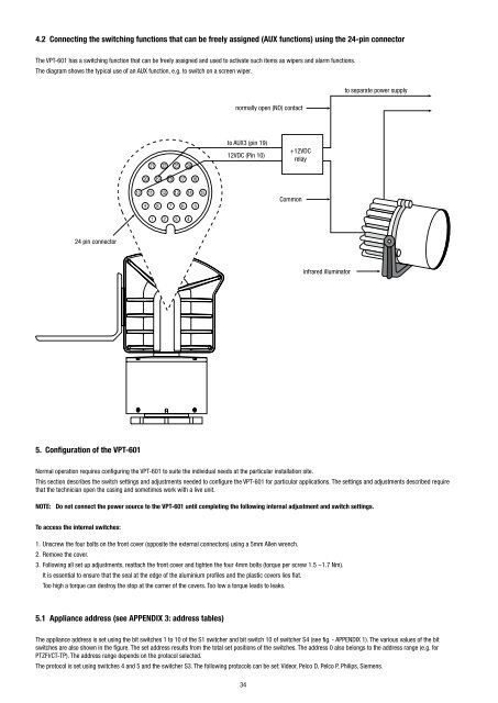
4.2 Connecting the switching functions that can be freely assigned (AUX functions) using the 24-pin connector<br />
The <strong>VPT</strong>-<strong>601</strong> has a switching function that can be freely assigned and used to activate such items as wipers and alarm functions.<br />
The diagram shows the typical use of an AUX function, e.g. to switch on a screen wiper.<br />
normally open (NO) contact<br />
to separate power supply<br />
21<br />
22<br />
23<br />
24<br />
to AUX3 (pin 19)<br />
12VDC (Pin 10)<br />
+12VDC<br />
relay<br />
20<br />
19<br />
18<br />
17<br />
16<br />
10 11 12 13 14 15<br />
9 8 7 6 5<br />
Common<br />
1 2 3 4<br />
24 pin connector<br />
infrared illuminator<br />
5. Configuration of the <strong>VPT</strong>-<strong>601</strong><br />
Normal operation requires configuring the <strong>VPT</strong>-<strong>601</strong> to suite the individual needs at the particular installation site.<br />
This section describes the switch settings and adjustments needed to configure the <strong>VPT</strong>-<strong>601</strong> for particular applications. The settings and adjustments described require<br />
that the technician open the casing and sometimes work <strong>with</strong> a live unit.<br />
NOTE: Do not connect the power source to the <strong>VPT</strong>-<strong>601</strong> until completing the following internal adjustment and switch settings.<br />
To access the internal switches:<br />
1. Unscrew the four bolts on the front cover (opposite the external connectors) using a 5mm Allen wrench.<br />
2. Remove the cover.<br />
3. Following all set up adjustments, reattach the front cover and tighten the four 4mm bolts (torque per screw 1.5 ~1.7 Nm).<br />
It is essential to ensure that the seal at the edge of the aluminium profiles and the plastic covers lies flat.<br />
Too high a torque can destroy the stop at the corner of the covers. Too low a torque leads to leaks.<br />
5.1 Appliance address (see APPENDIX 3: address tables)<br />
The appliance address is set using the bit switches 1 to 10 of the S1 switcher and bit switch 10 of switcher S4 (see fig. - APPENDIX 1). The various values of the bit<br />
switches are also shown in the figure. The set address results from the total set positions of the switches. The address 0 also belongs to the address range (e.g. for<br />
PTZFI/CT-TP). The address range depends on the protocol selected.<br />
The protocol is set using switches 4 and 5 and the switcher S3. The following protocols can be set: Videor, Pelco D, Pelco P, Philips, Siemens.<br />
34